Setup Manual
Page 1
... without obligation to notify any purpose. D uplication of this user's manual is subject to provide reasonable protec tion against harmful interference in a particular ins tallation. P4M900-M7 FE Setup Manual FCC Information and Copyright This equipment has been tes ted and found in writing. T his equipment generates , uses , and c an radiate radio frequency...
... without obligation to notify any purpose. D uplication of this user's manual is subject to provide reasonable protec tion against harmful interference in a particular ins tallation. P4M900-M7 FE Setup Manual FCC Information and Copyright This equipment has been tes ted and found in writing. T his equipment generates , uses , and c an radiate radio frequency...
Setup Manual
Page 2
Table of Contents Chapter 1: Introduction 3 1.1 Before You Start 3 1.2 Package Checklist 3 1.3 Motherboard Features 4 1.4 Rear Panel Connectors 5 1.5 Motherboard Layout 6 Chapter 2: Hardware Installation 7 2.1 Installing Central Processing Unit (CPU 7 2.2 Fan Headers 9 2.3 Installing System Memory 10 2.4 Connectors and Slots 12 Chapter 3: Headers & Jumpers Setup 14 3.1 How to Setup Jumpers 14 3.2 Detail Settings 14 Chapter 4: RAID Functions 20 4.1 Operation System 20 4.2 Raid Arrays 20 4.3 How RAID Works 20 Chapter 5: Useful Help 22 5.1 ...
Table of Contents Chapter 1: Introduction 3 1.1 Before You Start 3 1.2 Package Checklist 3 1.3 Motherboard Features 4 1.4 Rear Panel Connectors 5 1.5 Motherboard Layout 6 Chapter 2: Hardware Installation 7 2.1 Installing Central Processing Unit (CPU 7 2.2 Fan Headers 9 2.3 Installing System Memory 10 2.4 Connectors and Slots 12 Chapter 3: Headers & Jumpers Setup 14 3.1 How to Setup Jumpers 14 3.2 Detail Settings 14 Chapter 4: RAID Functions 20 4.1 Operation System 20 4.2 Raid Arrays 20 4.3 How RAID Works 20 Chapter 5: Useful Help 22 5.1 ...
Setup Manual
Page 3
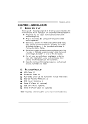
... grounded wrist strap to be nd or flex the board. „ Do not leave any unfastene d small parts inside ) Rear I/O Panel for choosing our product. P4M900-M7 FE CHAPTER 1: INTRODUCTION 1.1 BEFORE YOU START Thank you take the mothe rboard out from dange rous a rea, such as hea t source , humid air and wate r. 1.2 PACKAGE...
... grounded wrist strap to be nd or flex the board. „ Do not leave any unfastene d small parts inside ) Rear I/O Panel for choosing our product. P4M900-M7 FE CHAPTER 1: INTRODUCTION 1.1 BEFORE YOU START Thank you take the mothe rboard out from dange rous a rea, such as hea t source , humid air and wate r. 1.2 PACKAGE...
Setup Manual
Page 4
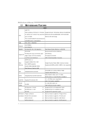
... Y 10 / 100 Mb/s auto negotiation Half / Full duplex capability Sound Codec ALC662 5.1 cha nnels a udio o ut High- FSB 533 / 800 / 1066 MHz Chipset Graphic VIA P4M900 VIA VT8237A Chrome9 HC 3D / 2D Graphics Max Share d Vide o Memory is not supported IDE Integrated I /O functionality. Motherboard Manual 1.3 MOT HERBOARD FEAT URES SPEC LGA...
... Y 10 / 100 Mb/s auto negotiation Half / Full duplex capability Sound Codec ALC662 5.1 cha nnels a udio o ut High- FSB 533 / 800 / 1066 MHz Chipset Graphic VIA P4M900 VIA VT8237A Chrome9 HC 3D / 2D Graphics Max Share d Vide o Memory is not supported IDE Integrated I /O functionality. Motherboard Manual 1.3 MOT HERBOARD FEAT URES SPEC LGA...
Setup Manual
Page 5
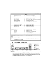
... Connects to RJ- 45 ether net cable x4 Connects to USB devices x3 Provide Audio-In/Out a nd microphone co nnection Micro ATX Size Board Biostar Reserves the right to a dd or r emove support for any OS with Smart Fa n function) x1 System Fan Power supply x1 Restore CMOS data to... Panel VGA Port I/O LAN port USB Port Audio J ack Board Size 190 mm (W) x 244 mm (L) Special Feature RAID 0 / 1 support OS Support Windows 2000 / XP / VISTA P4M900-M7 FE SPEC x1 Supports front panel facilities x1 Supports front panel a udio function x1 Supports CD audio-in Co nnector CPU Fan hea der System Fan...
... Connects to RJ- 45 ether net cable x4 Connects to USB devices x3 Provide Audio-In/Out a nd microphone co nnection Micro ATX Size Board Biostar Reserves the right to a dd or r emove support for any OS with Smart Fa n function) x1 System Fan Power supply x1 Restore CMOS data to... Panel VGA Port I/O LAN port USB Port Audio J ack Board Size 190 mm (W) x 244 mm (L) Special Feature RAID 0 / 1 support OS Support Windows 2000 / XP / VISTA P4M900-M7 FE SPEC x1 Supports front panel facilities x1 Supports front panel a udio function x1 Supports CD audio-in Co nnector CPU Fan hea der System Fan...
Setup Manual
Page 6
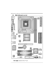
Motherboard Manual 1.5 MOT HERBOARD LAYOUT JKB MS1 LGA775 JCFAN1 COJMC1OM1 CPU1 JATXPWR1 JVGA1 DIMM1 DIMM2 JPRNT1 JUSB1 JUSBV1 JATXPWR2 J US BLAN1 P4M900 IDE1 IDE2 JAUDIO1 LAN PCI-E X16 Super I/O BAT1 PCI-EX1_1 JCDIN1 Codec JAUDIOF1 PCI1 PCI2 BIOS JU SB2 VIA VT8237A JUSB3 FDD1 JUSBV2 JCMOS1 JPAN EL 1 JSATA2 JSATA1 JSFAN1 Not e: ■ represe nts the 1st pin. 6
Motherboard Manual 1.5 MOT HERBOARD LAYOUT JKB MS1 LGA775 JCFAN1 COJMC1OM1 CPU1 JATXPWR1 JVGA1 DIMM1 DIMM2 JPRNT1 JUSB1 JUSBV1 JATXPWR2 J US BLAN1 P4M900 IDE1 IDE2 JAUDIO1 LAN PCI-E X16 Super I/O BAT1 PCI-EX1_1 JCDIN1 Codec JAUDIOF1 PCI1 PCI2 BIOS JU SB2 VIA VT8237A JUSB3 FDD1 JUSBV2 JCMOS1 JPAN EL 1 JSATA2 JSATA1 JSFAN1 Not e: ■ represe nts the 1st pin. 6
Setup Manual
Page 7
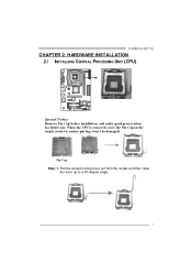
Pin Cap Step 1: Pull the socket locking lever out from the socket and then raise the lever up to ensure pin legs won't be damaged. When the CPU is removed, cover the Pin Cap on the empty socket to a 90-degree angle. 7 P4M900-M7 FE CHAPTER 2: HARDWARE INSTALLATION 2.1 INST ALLING CENT RAL PROCESSING UNIT (CPU) Special Notice: Remove Pin Cap before installation, and make good preservation for future use.
Pin Cap Step 1: Pull the socket locking lever out from the socket and then raise the lever up to ensure pin legs won't be damaged. When the CPU is removed, cover the Pin Cap on the empty socket to a 90-degree angle. 7 P4M900-M7 FE CHAPTER 2: HARDWARE INSTALLATION 2.1 INST ALLING CENT RAL PROCESSING UNIT (CPU) Special Notice: Remove Pin Cap before installation, and make good preservation for future use.
Setup Manual
Page 8
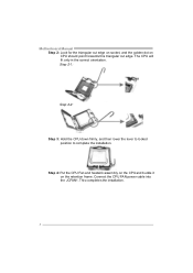
Motherboard Manual Step 2: Look for the triangular cut edge. Step 4: Put the CPU Fan and heatsink assembly on the CPU and buckle it on CPU should point forwards this triangular cut edge on socket, and the golden dot on the retention frame. Connect the CPU FAN power cable into the JCFAN1. The CPU will fit only in the correct orientation. Step 2-1: Step 2-2: Step 3: Hold the CPU down firmly, and then lower the lever to locked position to complete the installation. This completes the installation. 8
Motherboard Manual Step 2: Look for the triangular cut edge. Step 4: Put the CPU Fan and heatsink assembly on the CPU and buckle it on CPU should point forwards this triangular cut edge on socket, and the golden dot on the retention frame. Connect the CPU FAN power cable into the JCFAN1. The CPU will fit only in the correct orientation. Step 2-1: Step 2-2: Step 3: Hold the CPU down firmly, and then lower the lever to locked position to complete the installation. This completes the installation. 8
Setup Manual
Page 9
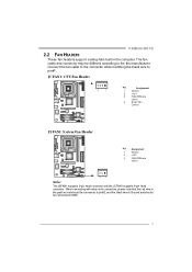
P4M900-M7 FE 2.2 FAN HEADERS These fan headers support cooling-fans built in the computer. When connecti ng with wires onto connectors, pl ease note that the r ed ...
P4M900-M7 FE 2.2 FAN HEADERS These fan headers support cooling-fans built in the computer. When connecti ng with wires onto connectors, pl ease note that the r ed ...
Setup Manual
Page 10
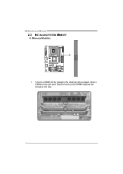
Align a DIMM on the slot such that the notch on the DIMM matches the break on the Slot. 10 Unlock a DIMM slot by pressing the retaining clips outward. DIMM1 DIMM2 Motherboard Manual 2.3 INST ALLING SYST EM MEMORY A. Memory Modules 1.
Align a DIMM on the slot such that the notch on the DIMM matches the break on the Slot. 10 Unlock a DIMM slot by pressing the retaining clips outward. DIMM1 DIMM2 Motherboard Manual 2.3 INST ALLING SYST EM MEMORY A. Memory Modules 1.
Setup Manual
Page 11
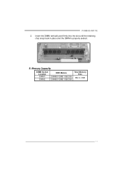
P4M900-M7 FE 2. B. Memory Capacity DIMM Socket Location DIMM1 DIMM2 DDR Module 256MB/512MB/1GB/2GB 256MB/512MB/1GB/2GB Total Memory Size Max is properly seated. Insert the DIMM vertically and firmly into the slot until the retaining chip snap back in place and the DIMM is 4GB. 11
P4M900-M7 FE 2. B. Memory Capacity DIMM Socket Location DIMM1 DIMM2 DDR Module 256MB/512MB/1GB/2GB 256MB/512MB/1GB/2GB Total Memory Size Max is properly seated. Insert the DIMM vertically and firmly into the slot until the retaining chip snap back in place and the DIMM is 4GB. 11
Setup Manual
Page 12
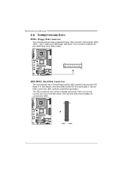
This connector supports the prov ided f loppy drive ribbon cable. 2 34 1 33 IDE1/IDE2: Hard Disk Conne ctors The motherboard has a 32-bit Enhanced PCI IDE Controller that supports 360K, 720K, 1.2M, 1.44M and 2.88M floppy disk ty pes. Motherboard Manual 2.4 CONNECT ORS AND SLOT S FDD1: Floppy Disk Conne ctor The motherboard prov ides a standard floppy disk connector that prov ides PIO Mode 0~4, Bus Master, and Ultra DMA 33/66/100/133 f unctionality. The f irst hard drive should always be connected to four hard disk drives. The IDE connectors can connect a master and a slav e ...
This connector supports the prov ided f loppy drive ribbon cable. 2 34 1 33 IDE1/IDE2: Hard Disk Conne ctors The motherboard has a 32-bit Enhanced PCI IDE Controller that supports 360K, 720K, 1.2M, 1.44M and 2.88M floppy disk ty pes. Motherboard Manual 2.4 CONNECT ORS AND SLOT S FDD1: Floppy Disk Conne ctor The motherboard prov ides a standard floppy disk connector that prov ides PIO Mode 0~4, Bus Master, and Ultra DMA 33/66/100/133 f unctionality. The f irst hard drive should always be connected to four hard disk drives. The IDE connectors can connect a master and a slav e ...
Setup Manual
Page 13
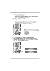
... - This PCI slot is equipped with 2 standard PCI slots. PCI-Express 1.0a compliant. - PCI-Express supports a raw bit-rate of 8GB/s totally. PCI1 PCI2 13 P4M900-M7 FE PCI-EX16: PCI-Express x16 Slot - PCI-Express 1.0a compliant. - PCI-EX 16 PCI-EX 1_1 PCI1/PCI2: Pe riphe ral Component Inte rconne ct...
... - This PCI slot is equipped with 2 standard PCI slots. PCI-Express 1.0a compliant. - PCI-Express supports a raw bit-rate of 8GB/s totally. PCI1 PCI2 13 P4M900-M7 FE PCI-EX16: PCI-Express x16 Slot - PCI-Express 1.0a compliant. - PCI-EX 16 PCI-EX 1_1 PCI1/PCI2: Pe riphe ral Component Inte rconne ct...
Setup Manual
Page 14
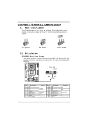
It allows user to set up jumpers. When the jumper cap is "open". PWR_LED On/Off ++ - 9 16 1 +- 8 SPK RST HLED Pin Assignment 1 +5V 2 N/A 3 N/A 4 Speaker 5 HDD LED (+) 6 HDD LED (-) 7 Ground 8 Reset control Functio n Pin 9 Speaker 10 Connec tor 11 12 Hard drive 13 LED 14 Reset button 15 16 Assignment N/A N/A N/A Power LED (+) Power LED (+) Power LED (-) Power button Ground Functio n N/A N/A Power LED Power-on pins, the jumper is "close", if not, that means the jumper is placed on button 14 Motherboard Manual CHAPTER 3: HEADERS & JUMPERS SETUP 3.1 HOW ...
It allows user to set up jumpers. When the jumper cap is "open". PWR_LED On/Off ++ - 9 16 1 +- 8 SPK RST HLED Pin Assignment 1 +5V 2 N/A 3 N/A 4 Speaker 5 HDD LED (+) 6 HDD LED (-) 7 Ground 8 Reset control Functio n Pin 9 Speaker 10 Connec tor 11 12 Hard drive 13 LED 14 Reset button 15 16 Assignment N/A N/A N/A Power LED (+) Power LED (+) Power LED (-) Power button Ground Functio n N/A N/A Power LED Power-on pins, the jumper is "close", if not, that means the jumper is placed on button 14 Motherboard Manual CHAPTER 3: HEADERS & JUMPERS SETUP 3.1 HOW ...
Setup Manual
Page 15
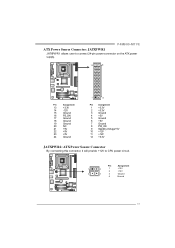
Pin Assignment 1 4 1 +12V 2 +12V 2 3 3 Ground 4 Ground 15 P4M900-M7 FE ATX Powe r Source Conne ctor: JATXPWR1 JATXPWR1 allows user to connect 24-pin power connector on the ATX power supply. 12 24 Pin Assignment 13 +3....
Pin Assignment 1 4 1 +12V 2 +12V 2 3 3 Ground 4 Ground 15 P4M900-M7 FE ATX Powe r Source Conne ctor: JATXPWR1 JATXPWR1 allows user to connect 24-pin power connector on the ATX power supply. 12 24 Pin Assignment 13 +3....
Setup Manual
Page 16
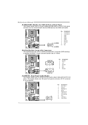
Pin Assignment 1 +5V (fused) 2 +5V (fused) 3 USB4 USB5 USB+ 6 USB+ 7 Ground 8 Ground 2 10 JUSB2 9 Key 10 NC 1 9 JUSB3 JSATA1/JSATA2: Se rial ATA Conne ctors The motherboard has a PCI to SATA Controller with 2 channels SATA interf ace, it satisfies the SATA 1.0 spec and with the PC f ront panel. AC'97 connector is not acceptable. 2 10 Pin Assignment 1 Mic Left in 2 Ground 3 Mic Right in 4 GPIO 5 Right line in 6 Jack Sense 7 Front Sense 8 Key 9 Left line in 10 Jack Sense 1 9 16 JSATA2 7 41 14 7 Pin Assignment 1 Ground 2 TX+ 3 TX4 Ground 5 RX6 RX+ 7 Ground J SATA1 JAUDIO F1: Front Panel...
Pin Assignment 1 +5V (fused) 2 +5V (fused) 3 USB4 USB5 USB+ 6 USB+ 7 Ground 8 Ground 2 10 JUSB2 9 Key 10 NC 1 9 JUSB3 JSATA1/JSATA2: Se rial ATA Conne ctors The motherboard has a PCI to SATA Controller with 2 channels SATA interf ace, it satisfies the SATA 1.0 spec and with the PC f ront panel. AC'97 connector is not acceptable. 2 10 Pin Assignment 1 Mic Left in 2 Ground 3 Mic Right in 4 GPIO 5 Right line in 6 Jack Sense 7 Front Sense 8 Key 9 Left line in 10 Jack Sense 1 9 16 JSATA2 7 41 14 7 Pin Assignment 1 Ground 2 TX+ 3 TX4 Ground 5 RX6 RX+ 7 Ground J SATA1 JAUDIO F1: Front Panel...
Setup Manual
Page 17
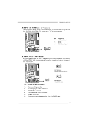
...: Cle ar CMOS Heade r By placing the jumper on the AC. 6. Remov e AC power line. 2. Reset y our desired password or clear the CMOS data. 17 P4M900-M7 FE JCDIN1: CD-RO M Audio-in Connector This connector allows user to avoid damaging the motherboard. 13 Pin 1-2 Close: Normal Operation (default). 13 13 Pin 2-3 Close...
...: Cle ar CMOS Heade r By placing the jumper on the AC. 6. Remov e AC power line. 2. Reset y our desired password or clear the CMOS data. 17 P4M900-M7 FE JCDIN1: CD-RO M Audio-in Connector This connector allows user to avoid damaging the motherboard. 13 Pin 1-2 Close: Normal Operation (default). 13 13 Pin 2-3 Close...
Setup Manual
Page 18
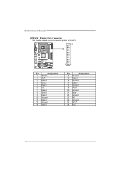
Motherboard Manual JPRNT1: Printe r Port Connector This header allows you to connector printer on the PC. 25 2 1 Pin Assignment 1 -Strobe 2 -ALF 3 Data 0 4 -Error 5 Data 1 6 -Init 7 Data 2 8 -Scltin 9 Data 3 10 Ground 11 Data 4 12 Ground 13 Data 5 Pin Assignment 14 Ground 15 Data 6 16 Ground 17 Data 7 18 Ground 19 -ACK 20 Ground 21 Busy 22 Ground 23 PE 24 Ground 25 SCLT 26 Key 18
Motherboard Manual JPRNT1: Printe r Port Connector This header allows you to connector printer on the PC. 25 2 1 Pin Assignment 1 -Strobe 2 -ALF 3 Data 0 4 -Error 5 Data 1 6 -Init 7 Data 2 8 -Scltin 9 Data 3 10 Ground 11 Data 4 12 Ground 13 Data 5 Pin Assignment 14 Ground 15 Data 6 16 Ground 17 Data 7 18 Ground 19 -ACK 20 Ground 21 Busy 22 Ground 23 PE 24 Ground 25 SCLT 26 Key 18

Setup Manual
Page 19
JUSBV1 13 13 Pin 1-2 close JU SBV 2 13 13 Pin 2-3 close Note: In order to support this function "Power-On system via USB device," "JUSBV1/ JUSBV2" jumper cap should be placed on Pin 2-3 indi viduall y. 19 JUSBV2: +5V for USB ports at JUSB1/JUSBLAN1 are powered by +5V standby v oltage. JUSBV2: USB ports at f ront panel (JUSB2/JUSB3). Pin 2-3 Close: JUSBV1: USB ports at JUSB1/JUSBLAN1. P4M900-M7 FE JUSBV1/JUSBV2: Powe r Source Heade rs for USB Ports Pin 1-2 Close: JUSBV1: +5V for USB ports at front panel (JUSB2/JUSB3) are powered by +5V standby v oltage.
JUSBV1 13 13 Pin 1-2 close JU SBV 2 13 13 Pin 2-3 close Note: In order to support this function "Power-On system via USB device," "JUSBV1/ JUSBV2" jumper cap should be placed on Pin 2-3 indi viduall y. 19 JUSBV2: +5V for USB ports at JUSB1/JUSBLAN1 are powered by +5V standby v oltage. JUSBV2: USB ports at f ront panel (JUSB2/JUSB3). Pin 2-3 Close: JUSBV1: USB ports at JUSB1/JUSBLAN1. P4M900-M7 FE JUSBV1/JUSBV2: Powe r Source Heade rs for USB Ports Pin 1-2 Close: JUSBV1: +5V for USB ports at front panel (JUSB2/JUSB3) are powered by +5V standby v oltage.
Setup Manual
Page 20
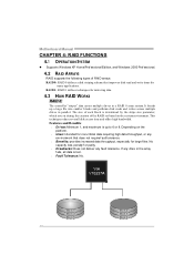
RAID 1: RAID 1 defines techniques for many applications. This technique reduces overall disk access time and offers high bandwidth. Depending on the system environment. Features and Benefits Drives: Minimum 1, and maximum is up a large file into smaller blocks and performs disk reads and writes across multiple drives in the array f ails, all data is determined by the stripe size parameter, which you set during the creation of RAID arrays: RAID 0: RAID 0 defines a disk striping scheme that does not require f ault tolerance. Benefits: prov ides increased data ...
RAID 1: RAID 1 defines techniques for many applications. This technique reduces overall disk access time and offers high bandwidth. Depending on the system environment. Features and Benefits Drives: Minimum 1, and maximum is up a large file into smaller blocks and performs disk reads and writes across multiple drives in the array f ails, all data is determined by the stripe size parameter, which you set during the creation of RAID arrays: RAID 0: RAID 0 defines a disk striping scheme that does not require f ault tolerance. Benefits: prov ides increased data ...