
P4M80-M7 user's manual
Page 11
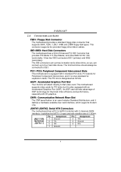
... Component Interconnect, and it defines a hardware scalable riser card interface, which supports modem only. JSATA1/JSATA2: Serial ATA Connectors The motherboard has a PCI to IDE1. This connector supports the provided floppy drive ribbon cables. It has two HDD connectors IDE1 (primary) ...to four hard disk drives. AGP1: Accelerated Graphics Port Slot Your monitor will take advantage of 1.5Gb/s. P4M80-M7 2.4 CONNECTORS AND SLOTS FDD1: Floppy Disk Connector The motherboard provides a standard floppy disk connector that supports 360K, 720K, 1.2M, 1.44M and 2.88M floppy disk types....
... Component Interconnect, and it defines a hardware scalable riser card interface, which supports modem only. JSATA1/JSATA2: Serial ATA Connectors The motherboard has a PCI to IDE1. This connector supports the provided floppy drive ribbon cables. It has two HDD connectors IDE1 (primary) ...to four hard disk drives. AGP1: Accelerated Graphics Port Slot Your monitor will take advantage of 1.5Gb/s. P4M80-M7 2.4 CONNECTORS AND SLOTS FDD1: Floppy Disk Connector The motherboard provides a standard floppy disk connector that supports 360K, 720K, 1.2M, 1.44M and 2.88M floppy disk types....

P4M80-M7 user's manual
Page 14
P4M80-M7 JCDIN1: CD-ROM Audio-in Connector This connector allows user to connect the PCI bracket SPDIF output header. Reset your desired password or clear the ... TV turner card etc.. Pin 2-3 close Normal Operation (Default). Wait for five seconds. 4. JCI1: Chassis Open Header This connector allows system to avoid damaging the motherboard. Pin Assignment 1 JSPDIFO1 1 +5V 2 SPDIF_OUT 3 Ground JCMOS1: Clear CMOS Header By placing the jumper on pin2-3, it will record to "Pin 1-2 close ". 3. Pin Assignment JCI1...
P4M80-M7 JCDIN1: CD-ROM Audio-in Connector This connector allows user to connect the PCI bracket SPDIF output header. Reset your desired password or clear the ... TV turner card etc.. Pin 2-3 close Normal Operation (Default). Wait for five seconds. 4. JCI1: Chassis Open Header This connector allows system to avoid damaging the motherboard. Pin Assignment 1 JSPDIFO1 1 +5V 2 SPDIF_OUT 3 Ground JCMOS1: Clear CMOS Header By placing the jumper on pin2-3, it will record to "Pin 1-2 close ". 3. Pin Assignment JCI1...

P4M80-M7 user's manual
Page 16
P4M80-M7 CHAPTER 4: USEFUL HELP 4.1 AWARD BIOS BEEP CODE Beep Sound One long beep followed by virus, the Boot-Block function will help to update BIOS or BIOS is shown after boot-up the system, it means the BIOS contents are corrupted. Confirm motherboard model and download the respectively BIOS from the Biostar... website: www.biostar.com.tw 3. The BIOS has been recovered and will update BIOS automatically and restart. 9....
P4M80-M7 CHAPTER 4: USEFUL HELP 4.1 AWARD BIOS BEEP CODE Beep Sound One long beep followed by virus, the Boot-Block function will help to update BIOS or BIOS is shown after boot-up the system, it means the BIOS contents are corrupted. Confirm motherboard model and download the respectively BIOS from the Biostar... website: www.biostar.com.tw 3. The BIOS has been recovered and will update BIOS automatically and restart. 9....

P4M80-M7 user's manual
Page 17
... CMOS Header: JCMOS1" section) 2. CPU fan is fulfilling with the CPU surface. 2. Plug in the power cord and boot up the system. Wait for seconds. 3. P4M80-M7 B. When the CPU is placed evenly with the CPU speed. After confirmed, please follow steps below to avoid a damage of the CPU, and the system... has been activated. Or you can: 1. Power on system for seconds. 2. CPU fan speed is rotated normally. 3. The CPU cooler surface is over heated, the motherboard will shutdown automatically to relief the CPU protection function. 1.
... CMOS Header: JCMOS1" section) 2. CPU fan is fulfilling with the CPU surface. 2. Plug in the power cord and boot up the system. Wait for seconds. 3. P4M80-M7 B. When the CPU is placed evenly with the CPU speed. After confirmed, please follow steps below to avoid a damage of the CPU, and the system... has been activated. Or you can: 1. Power on system for seconds. 2. CPU fan speed is rotated normally. 3. The CPU cooler surface is over heated, the motherboard will shutdown automatically to relief the CPU protection function. 1.

P4M80-M7 user's manual
Page 20
P4M80-M7 5.3 1. When you click "Finish" button. If the "Launch the WarpSpeeder Tray Utility" checkbox is completed. Please click "Next" button and follow the default procedure to your motherboard on hand. 18 Usage: The following dialog in this user manual will change according to install. 2. INSTALLATION Execute the setup execution file, and then the...
P4M80-M7 5.3 1. When you click "Finish" button. If the "Launch the WarpSpeeder Tray Utility" checkbox is completed. Please click "Next" button and follow the default procedure to your motherboard on hand. 18 Usage: The following dialog in this user manual will change according to install. 2. INSTALLATION Execute the setup execution file, and then the...

P4M80-M7 BIOS guide
Page 23
P4M80-M7 BIOS Manual 5.1 VIA OnChip IDE Device The chipset contains a PCI IDE interface with support for two IDE channels. Select "Enabled" to activate the first and / ... a primary and/or secondary add-in IDE interface. The Choices: Enabled (default), Disabled. 5.1.2 IDE DMA Transfer Access The Choices: Enabled (default), Disabled. 5.1.3 IDE Channel 0/1 The motherboard chipset contains a PCI IDE interface with support for faster drive access. If you to "Disabled". Select "Enabled" to activate the first and/or second IDE...
P4M80-M7 BIOS Manual 5.1 VIA OnChip IDE Device The chipset contains a PCI IDE interface with support for two IDE channels. Select "Enabled" to activate the first and / ... a primary and/or secondary add-in IDE interface. The Choices: Enabled (default), Disabled. 5.1.2 IDE DMA Transfer Access The Choices: Enabled (default), Disabled. 5.1.3 IDE Channel 0/1 The motherboard chipset contains a PCI IDE interface with support for faster drive access. If you to "Disabled". Select "Enabled" to activate the first and/or second IDE...

P4M80-M7 BIOS guide
Page 30
... after S3 . There are 3 options: "Former-Sts", "On", "Off". If AC power is lost when system is not supplying power, the motherboard uses the motherboard battery (3V). For example: If set to initialize the card . The Choices:Auto, Yes (default), No. 6.11 Ac Loss Auto Restart This...BTN Pressing the power button for more than 4 seconds forces the system to a system that retains these Power-On instructions; the motherboard battery (3V), the Power Supply (5VSB), and the Power Supply (3.3V). P4M80-M7 BIOS Manual 6.8 Modem Use IRQ This determines the IRQ, which can be used .
... after S3 . There are 3 options: "Former-Sts", "On", "Off". If AC power is lost when system is not supplying power, the motherboard uses the motherboard battery (3V). For example: If set to initialize the card . The Choices:Auto, Yes (default), No. 6.11 Ac Loss Auto Restart This...BTN Pressing the power button for more than 4 seconds forces the system to a system that retains these Power-On instructions; the motherboard battery (3V), the Power Supply (5VSB), and the Power Supply (3.3V). P4M80-M7 BIOS Manual 6.8 Modem Use IRQ This determines the IRQ, which can be used .


