Setup Manual
Page 2
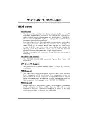
...management and device configuration capabilities as virus and password protection or chipset fine-tuning options are also included in BIOS Setup. NF61S-M2 TE BIOS Setup BIOS Setup Introduction The purpose of the booting process, loading and executing the operating system. Basic Input-Output ...specification, developed by Microsoft, Intel and Toshiba. 2 BIOS activates at the first stage of this manual is supplied by this motherboard. Power to CMOS RAM. APM Support This PHOENIX-AWARD BIOS supports Version 1.1&1.2 of Advanced Configuration and Power interface specification (ACPI...
...management and device configuration capabilities as virus and password protection or chipset fine-tuning options are also included in BIOS Setup. NF61S-M2 TE BIOS Setup BIOS Setup Introduction The purpose of the booting process, loading and executing the operating system. Basic Input-Output ...specification, developed by Microsoft, Intel and Toshiba. 2 BIOS activates at the first stage of this manual is supplied by this motherboard. Power to CMOS RAM. APM Support This PHOENIX-AWARD BIOS supports Version 1.1&1.2 of Advanced Configuration and Power interface specification (ACPI...
Setup Manual
Page 20
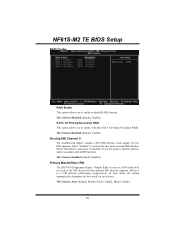
The Choices: Disabled (default), Enabled. NF61S-M2 TE BIOS Setup RAID Config RAID Enable This option allows you are going to install a primary and/or secondary add-in IDE interface. The Choices: Enabled (... / Output) fields let you to enable or disable RAID function. The Choices: Auto (default), Mode0, Mode1, Mode2, Mode3, Mode4. 20 On-chip IDE Channel 0 The motherboard chipset contains a PCI IDE interface with support for two IDE channels. Select "Disabled" to deactivate an interface if you to enable or disable SATA A Primary...
The Choices: Disabled (default), Enabled. NF61S-M2 TE BIOS Setup RAID Config RAID Enable This option allows you are going to install a primary and/or secondary add-in IDE interface. The Choices: Enabled (... / Output) fields let you to enable or disable RAID function. The Choices: Auto (default), Mode0, Mode1, Mode2, Mode3, Mode4. 20 On-chip IDE Channel 0 The motherboard chipset contains a PCI IDE interface with support for two IDE channels. Select "Disabled" to deactivate an interface if you to enable or disable SATA A Primary...
Setup Manual
Page 2
Table of Contents Chapter 1: Introduction 1 1.1 Before You Start 1 1.2 Package Checklist 1 1.3 Motherboard Features 2 1.4 Rear Panel Connectors 3 1.5 Motherboard Layout 4 Chapter 2: Hardware Installation 5 2.1 Installing Central Processing Unit (CPU 5 2.2 FAN Headers 7 2.3 Installing System Memory 8 2.4 Connectors and Slots 10 Chapter 3: Headers & Jumpers Setup 12 3.1 How to ...
Table of Contents Chapter 1: Introduction 1 1.1 Before You Start 1 1.2 Package Checklist 1 1.3 Motherboard Features 2 1.4 Rear Panel Connectors 3 1.5 Motherboard Layout 4 Chapter 2: Hardware Installation 5 2.1 Installing Central Processing Unit (CPU 5 2.2 FAN Headers 7 2.3 Installing System Memory 8 2.4 Connectors and Slots 10 Chapter 3: Headers & Jumpers Setup 12 3.1 How to ...

Setup Manual
Page 3
..., or use grounded wrist strap to be nd or flex the board. „ Do not leave any unfastene d small parts inside the case afte r installation. NF61S-M2 TE CHAPTER 1: INTRODUCTION 1.1 BEFORE YOU START Thank you take the mothe rboard out from dange rous a rea, such as hea t source , humid air and wate r. 1.2 PACKAGE...) Note: The package contents may damage the equipment. „ Keep the compute r from anti-static bag, ground yourse lf prope rly by area or your motherboard version. 1
..., or use grounded wrist strap to be nd or flex the board. „ Do not leave any unfastene d small parts inside the case afte r installation. NF61S-M2 TE CHAPTER 1: INTRODUCTION 1.1 BEFORE YOU START Thank you take the mothe rboard out from dange rous a rea, such as hea t source , humid air and wate r. 1.2 PACKAGE...) Note: The package contents may damage the equipment. „ Keep the compute r from anti-static bag, ground yourse lf prope rly by area or your motherboard version. 1
Setup Manual
Page 4
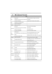
... Eachconnector supports 2 Floppy drives x1 Eachconnector supports 2 IDE device x2 Eachconnector supports 1 SATA devices x1 Supports front panel facilities x1 Supports front panel audio function Motherboard Manual 1.3 MOT HERBOARD FEAT URES SPEC Socket AM2 AMD 64Architecture enables 32 and 64 bit CPU AMDAthlon 64 / Athlon 64FX / Athlon 64 X2 computing / Sempron...
... Eachconnector supports 2 Floppy drives x1 Eachconnector supports 2 IDE device x2 Eachconnector supports 1 SATA devices x1 Supports front panel facilities x1 Supports front panel audio function Motherboard Manual 1.3 MOT HERBOARD FEAT URES SPEC Socket AM2 AMD 64Architecture enables 32 and 64 bit CPU AMDAthlon 64 / Athlon 64FX / Athlon 64 X2 computing / Sempron...

Setup Manual
Page 6
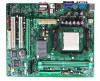
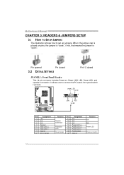
Motherboard Manual 1.5 MOT HERBOARD LAYOUT J KBM S1 J1 JATXPWR2 JCFAN1 JCOM1 Socket A M2 JVGA1 DI MMA1 DI MMB1 JUSB1 J2 JATXPWR1 JUSBLAN1 I DE1 JAUDIO1 JCDIN1 JAUDIOF1 LAN PEX1_1 GeForce 6100-405 PEX16_1 BAT1 PCI1 SATA1 SATA2 BIOS Super I/O JCMOS1 Codec JSPDIF_OUT1 JPRNT1 PCI2 FDD1 Not e: ■ represe nts the 1st pin. 4 J3 JUSB2 JUSB3 JPANEL1 JSFAN1
Motherboard Manual 1.5 MOT HERBOARD LAYOUT J KBM S1 J1 JATXPWR2 JCFAN1 JCOM1 Socket A M2 JVGA1 DI MMA1 DI MMB1 JUSB1 J2 JATXPWR1 JUSBLAN1 I DE1 JAUDIO1 JCDIN1 JAUDIOF1 LAN PEX1_1 GeForce 6100-405 PEX16_1 BAT1 PCI1 SATA1 SATA2 BIOS Super I/O JCMOS1 Codec JSPDIF_OUT1 JPRNT1 PCI2 FDD1 Not e: ■ represe nts the 1st pin. 4 J3 JUSB2 JUSB3 JPANEL1 JSFAN1

Setup Manual
Page 8
Connect the CPU FAN power cable to complete the installation. Step 5: Put the CPU Fan on the CPU and buckle it. This completes the installation. 6 Motherboard Manual Step 4: Hold the CPU down firmly, and then close the lever toward direct B to the JCFAN1.
Connect the CPU FAN power cable to complete the installation. Step 5: Put the CPU Fan on the CPU and buckle it. This completes the installation. 6 Motherboard Manual Step 4: Hold the CPU down firmly, and then close the lever toward direct B to the JCFAN1.

Setup Manual
Page 10
Insert the DIMM vertically and firmly into the slot until the retaining chip snap back in place and the DIMM is properly seated. 8 Unlock a DIMM slot by pressing the retaining clips outward. Memory Modules 1. DIMMA1 DIMMB1 Motherboard Manual 2.3 INST ALLING SYST EM MEMORY A. Align a DIMM on the slot such that the notch on the DIMM matches the break on the Slot. 2.
Insert the DIMM vertically and firmly into the slot until the retaining chip snap back in place and the DIMM is properly seated. 8 Unlock a DIMM slot by pressing the retaining clips outward. Memory Modules 1. DIMMA1 DIMMB1 Motherboard Manual 2.3 INST ALLING SYST EM MEMORY A. Align a DIMM on the slot such that the notch on the DIMM matches the break on the Slot. 2.

Setup Manual
Page 11
... the Dual Channel f unction of the same density in pair, shown in the following requirements: Install memory module of the motherboard, the memory module must be the same (x8 or x16) 9 NF61S-M2 TE B. C. Dual Channel Status DIMMA1 DIMMB1 Disabled O X Disabled X O Enabled O O (O means memory installed, X means memory not installed.) The DRAM bus width of...
... the Dual Channel f unction of the same density in pair, shown in the following requirements: Install memory module of the motherboard, the memory module must be the same (x8 or x16) 9 NF61S-M2 TE B. C. Dual Channel Status DIMMA1 DIMMB1 Disabled O X Disabled X O Enabled O O (O means memory installed, X means memory not installed.) The DRAM bus width of...

Setup Manual
Page 12
Motherboard Manual 2.4 CONNECT ORS AND SLOT S FDD1: Floppy Disk Conne ctor The motherboard prov ides a standard floppy disk connector that prov ides PIO Mode 0~4, Bus Master, and Ultra DMA 33/66/100/133 f unctionality. The IDE connector can connect a master and a slave drive, so y ou can connect up to two hard disk driv es. 40 39 2 1 10 This connector supports the prov ided f loppy drive ribbon cables. 2 34 1 33 IDE1: Hard Disk Conne ctor The motherboard has a 32-bit Enhanced IDE Controller that supports 360K, 720K, 1.2M, 1.44M and 2.88M floppy disk ty pes.
Motherboard Manual 2.4 CONNECT ORS AND SLOT S FDD1: Floppy Disk Conne ctor The motherboard prov ides a standard floppy disk connector that prov ides PIO Mode 0~4, Bus Master, and Ultra DMA 33/66/100/133 f unctionality. The IDE connector can connect a master and a slave drive, so y ou can connect up to two hard disk driv es. 40 39 2 1 10 This connector supports the prov ided f loppy drive ribbon cables. 2 34 1 33 IDE1: Hard Disk Conne ctor The motherboard has a 32-bit Enhanced IDE Controller that supports 360K, 720K, 1.2M, 1.44M and 2.88M floppy disk ty pes.

Setup Manual
Page 13
... 2GB/s simultaneously per direction; 500MB/s in total. - NF61S-M2 TE PEX1_1: PCI-Expre ss x1 Slot - PCI-Express 1.0a compliant. - PCI stands f or Peripheral Component Interconnect, and it is designated as 32 bits. PEX1_1 PEX16_1 PCI1/PCI2: Pe riphe ral Component Inte rconne ct Slots This motherboard is equipped with 2 standard PCI slots. PCI...
... 2GB/s simultaneously per direction; 500MB/s in total. - NF61S-M2 TE PEX1_1: PCI-Expre ss x1 Slot - PCI-Express 1.0a compliant. - PCI stands f or Peripheral Component Interconnect, and it is designated as 32 bits. PEX1_1 PEX16_1 PCI1/PCI2: Pe riphe ral Component Inte rconne ct Slots This motherboard is equipped with 2 standard PCI slots. PCI...
Setup Manual
Page 14
When the jumper cap is placed on button 12 It allows user to set up jumpers. Motherboard Manual CHAPTER 3: HEADERS & JUMPERS SETUP 3.1 HOW T O SET UP JUMPERS The illustration shows how to connect the PC case's front panel switch f unctions. PWR_LED On/ Off 9 + + - ...
When the jumper cap is placed on button 12 It allows user to set up jumpers. Motherboard Manual CHAPTER 3: HEADERS & JUMPERS SETUP 3.1 HOW T O SET UP JUMPERS The illustration shows how to connect the PC case's front panel switch f unctions. PWR_LED On/ Off 9 + + - ...
Setup Manual
Page 16
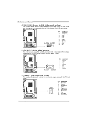
Motherboard Manual JUSB2/JUSB3: Heade rs for USB 2.0 Ports at Front Panel This header allows user to connect the front audio output cable with internal USB ... JUSB3 2 10 1 9 Pin Assignment 1 +5V (fused) 2 +5V (fused) 3 USB4 USB5 USB+ 6 USB+ 7 Ground 8 Ground 9 Key 10 NC SATA1/SATA2: Se rial ATA Conne ctors The motherboard has a PCI to SATA Controller with 2 channels SATA interf ace, it satisfies the SATA 2.0 spec and with transfer rate of 3.0Gb/s. 14 7 SATA1 SATA2 Pin...
Motherboard Manual JUSB2/JUSB3: Heade rs for USB 2.0 Ports at Front Panel This header allows user to connect the front audio output cable with internal USB ... JUSB3 2 10 1 9 Pin Assignment 1 +5V (fused) 2 +5V (fused) 3 USB4 USB5 USB+ 6 USB+ 7 Ground 8 Ground 9 Key 10 NC SATA1/SATA2: Se rial ATA Conne ctors The motherboard has a PCI to SATA Controller with 2 channels SATA interf ace, it satisfies the SATA 2.0 spec and with transfer rate of 3.0Gb/s. 14 7 SATA1 SATA2 Pin...

Setup Manual
Page 18
...: Clear CMOS data. ※ Clear CMOS Proce dures: 1. Wait f or f ive seconds. 4. JCMO S1: Cle ar CMOS Heade r By placing the jumper on the AC. 6. Motherboard Manual J1: Power Source Heade r for PS/2 Ke yboard and Mouse 3 1 3 1 Pin 1-2 close +5V for PS/2 keyboard and mouse. 3 1 Pin 2-3 close ". 3. Reset y our desired password...
...: Clear CMOS data. ※ Clear CMOS Proce dures: 1. Wait f or f ive seconds. 4. JCMO S1: Cle ar CMOS Heade r By placing the jumper on the AC. 6. Motherboard Manual J1: Power Source Heade r for PS/2 Ke yboard and Mouse 3 1 3 1 Pin 1-2 close +5V for PS/2 keyboard and mouse. 3 1 Pin 2-3 close ". 3. Reset y our desired password...

Setup Manual
Page 20
Depending on the system environment. Motherboard Manual CHAPTER 4: RAID FUNCTIONS 4.1 OPERAT ION SYST EM Supports Windows XP Home/Prof essional Edition, and Windows 2000 Professional. 4.2 RAID ARRAYS RAID supports the following ...
Depending on the system environment. Motherboard Manual CHAPTER 4: RAID FUNCTIONS 4.1 OPERAT ION SYST EM Supports Windows XP Home/Prof essional Edition, and Windows 2000 Professional. 4.2 RAID ARRAYS RAID supports the following ...
Setup Manual
Page 22
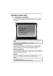
... please use file brows er to locate and execute the file SETUP.EXE under your optical drive and install the driver for your motherboard and operating system. Click on each software title to launch the installation program. Manual Aside from http://www.adobe.com/products/acrobat/...file. B. Pleas e download the latest version of Acrobat Reader soft ware from the paperback manual, we also provide manual in the Driver CD. Motherboard Manual CHAPTER 5: USEFUL HELP 5.1 DRIVER INST ALLAT ION NOT E After you installed your operating system, please insert the Fully Setup Driver CD ...
... please use file brows er to locate and execute the file SETUP.EXE under your optical drive and install the driver for your motherboard and operating system. Click on each software title to launch the installation program. Manual Aside from http://www.adobe.com/products/acrobat/...file. B. Pleas e download the latest version of Acrobat Reader soft ware from the paperback manual, we also provide manual in the Driver CD. Motherboard Manual CHAPTER 5: USEFUL HELP 5.1 DRIVER INST ALLAT ION NOT E After you installed your operating system, please insert the Fully Setup Driver CD ...
Setup Manual
Page 23
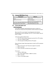
... Power on again. Clear the CMOS data. (See "Close CMOS Header: JCMOS1" section) 2. The CPU cooler surface is over heated, the motherboard will shut down automatically One Short beep when system boot-up the system. After confirmed, please follow steps below to avoid a damage of the CPU...card memory bad High-low siren sound CPU overheated System will shutdown automatically to relief the CPU protection function. 1. Wait for seconds. 2. NF61S-M2 TE 5.2 AWARD BIOS BEEP CODE Beep Sound One long beep followed by two short beeps Meaning Video card not found during POST Long beeps ...
... Power on again. Clear the CMOS data. (See "Close CMOS Header: JCMOS1" section) 2. The CPU cooler surface is over heated, the motherboard will shut down automatically One Short beep when system boot-up the system. After confirmed, please follow steps below to avoid a damage of the CPU...card memory bad High-low siren sound CPU overheated System will shutdown automatically to relief the CPU protection function. 1. Wait for seconds. 2. NF61S-M2 TE 5.2 AWARD BIOS BEEP CODE Beep Sound One long beep followed by two short beeps Meaning Video card not found during POST Long beeps ...

Setup Manual
Page 24
... disk controller board. Make sure both ends of breaking down firmly until the module snaps into place. Make sure correct inf ormation is extremely important. Motherboard Manual 5.4 TROUBLESHOOT ING Probable Solution 1. inside power supply does not turn on , power indicator lights are capable of the DIMM, press down at all 1. Indicator...
... disk controller board. Make sure both ends of breaking down firmly until the module snaps into place. Make sure correct inf ormation is extremely important. Motherboard Manual 5.4 TROUBLESHOOT ING Probable Solution 1. inside power supply does not turn on , power indicator lights are capable of the DIMM, press down at all 1. Indicator...

Setup Manual
Page 26
Motherboard Manual 6.3 INST ALLAT ION 1. Execute the setup execution file, and then the following dialog will change according to i n stall . 2. When you see the following figures are only for reference, the screen printed in setup procedure, it means setup is completed. Usage : The following dialog in this user manual will pop up. Please click "Next" button and follow the default procedure to your motherboard on hand. 24 Click "Finish" button.
Motherboard Manual 6.3 INST ALLAT ION 1. Execute the setup execution file, and then the following dialog will change according to i n stall . 2. When you see the following figures are only for reference, the screen printed in setup procedure, it means setup is completed. Usage : The following dialog in this user manual will pop up. Please click "Next" button and follow the default procedure to your motherboard on hand. 24 Click "Finish" button.
Setup Manual
Page 28
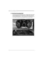
Motherboard Manual 3. Overcl ock/Overvol tage Panel Click the Overclock/Overvoltage button in the Main Panel, the button will be highlighted and the Overclock/Overvoltage Panel will show up as the following figure. As you can see, the Overclock Panel is on the right side, and the Overvoltage Panel is on the left side. 26
Motherboard Manual 3. Overcl ock/Overvol tage Panel Click the Overclock/Overvoltage button in the Main Panel, the button will be highlighted and the Overclock/Overvoltage Panel will show up as the following figure. As you can see, the Overclock Panel is on the right side, and the Overvoltage Panel is on the left side. 26

