
Setup Manual
Page 2
Table of Contents Chapter 1: Introduction 1 1.1 Before You Start 1 1.2 Package Checklist 1 1.3 Motherboard Features 2 1.4 Rear Panel Connectors 3 1.5 Motherboard Layout 4 Chapter 2: Hardware Installation 5 2.1 Installing Central Processing Unit (CPU 5 2.2 FAN Headers 7 2.3 Installing System Memory 8 2.4 Connectors and Slots 10 Chapter 3: Headers & Jumpers Setup 14 3.1 How to ...
Table of Contents Chapter 1: Introduction 1 1.1 Before You Start 1 1.2 Package Checklist 1 1.3 Motherboard Features 2 1.4 Rear Panel Connectors 3 1.5 Motherboard Layout 4 Chapter 2: Hardware Installation 5 2.1 Installing Central Processing Unit (CPU 5 2.2 FAN Headers 7 2.3 Installing System Memory 8 2.4 Connectors and Slots 10 Chapter 3: Headers & Jumpers Setup 14 3.1 How to ...
Setup Manual
Page 3
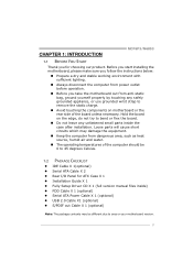
.... Loose parts will cause short circuits which may be different due to remove the static charge. Before you start installing the motherboard, please make sure you follow the instructions below: Prepare a dry and stable working environment with sufficient lighting. Avoid touching the... Celsius. 1.2 PACKAGE CHECKLIST IDE Cable X 1(optional) Serial ATA Cable X 2 Rear I/O Panel for choosing our product. CHAPTER 1: INTRODUCTION MCP6P3/N68S3 1.1 BEFORE YOU START Thank you for ATX Case X 1 Installation Guide X 1 Fully Setup Driver CD X 1 (full version manual files inside the case...
.... Loose parts will cause short circuits which may be different due to remove the static charge. Before you start installing the motherboard, please make sure you follow the instructions below: Prepare a dry and stable working environment with sufficient lighting. Avoid touching the... Celsius. 1.2 PACKAGE CHECKLIST IDE Cable X 1(optional) Serial ATA Cable X 2 Rear I/O Panel for choosing our product. CHAPTER 1: INTRODUCTION MCP6P3/N68S3 1.1 BEFORE YOU START Thank you for ATX Case X 1 Installation Guide X 1 Fully Setup Driver CD X 1 (full version manual files inside the case...
Setup Manual
Page 4
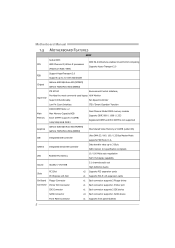
... Master Mode supports PIO Mode 0~4, SATA II Integrated Serial ATA Controller Data transfer rates up to 3 Gb/s. Motherboard Manual 1.3 MOTHERBOARD FEATURES SPEC Socket AM3 AMD 64 Architecture enables 32 and 64 bit computing CPU AMD Phenom II/ Athlon II ...processors Supports Hyper Transport 2.0 (Maximum Watt: 95W) Support HyperTransport 2.0 FSB Supports up to 2.0 GT/s Bandwidth Chipset GeForce 6150 SE/nForce 430 (MCP6P3) GeForce 7025/nForce 630a (N68S3...
... Master Mode supports PIO Mode 0~4, SATA II Integrated Serial ATA Controller Data transfer rates up to 3 Gb/s. Motherboard Manual 1.3 MOTHERBOARD FEATURES SPEC Socket AM3 AMD 64 Architecture enables 32 and 64 bit computing CPU AMD Phenom II/ Athlon II ...processors Supports Hyper Transport 2.0 (Maximum Watt: 95W) Support HyperTransport 2.0 FSB Supports up to 2.0 GT/s Bandwidth Chipset GeForce 6150 SE/nForce 430 (MCP6P3) GeForce 7025/nForce 630a (N68S3...

Setup Manual
Page 6
Motherboard Manual 1.5 MOTHERBOARD LAYOUT KBMS1 AT X P W R2 JK B _P WR CP U_FAN1 COM1 DDR3_A1 DDR3_B1 Socket AM3 VGA1 USB1 RJ45USB1 JUS B V 1 AT X P WR1 AUDIO1 F _ A UDIO 1 -"/ BAT1 GeForce 6150 SE/7025 nForce 430/630a PEX16_1 PCI1 Codec JP RINT 1 PCI2 FDD1 JS P DIF O UT 1 Note: ■ represents the 1st pin. Super I/O JUS B V2 IDE1 F_USB2 F_USB1 BIOS JCMOS1 SATA2 SATA4 SATA1 SATA3 S YS_FAN1 PANEL1 4
Motherboard Manual 1.5 MOTHERBOARD LAYOUT KBMS1 AT X P W R2 JK B _P WR CP U_FAN1 COM1 DDR3_A1 DDR3_B1 Socket AM3 VGA1 USB1 RJ45USB1 JUS B V 1 AT X P WR1 AUDIO1 F _ A UDIO 1 -"/ BAT1 GeForce 6150 SE/7025 nForce 430/630a PEX16_1 PCI1 Codec JP RINT 1 PCI2 FDD1 JS P DIF O UT 1 Note: ■ represents the 1st pin. Super I/O JUS B V2 IDE1 F_USB2 F_USB1 BIOS JCMOS1 SATA2 SATA4 SATA1 SATA3 S YS_FAN1 PANEL1 4

Setup Manual
Page 8
Motherboard Manual Step 3: Hold the CPU down firmly, and then close the lever toward direct B to the CPU_FAN1. Connect the CPU FAN power cable to complete the installation. Step 4: Put the CPU Fan on the CPU and buckle it. This completes the installation. 6
Motherboard Manual Step 3: Hold the CPU down firmly, and then close the lever toward direct B to the CPU_FAN1. Connect the CPU FAN power cable to complete the installation. Step 4: Put the CPU Fan on the CPU and buckle it. This completes the installation. 6

Setup Manual
Page 10
Align a DIMM on the slot such that the notch on the DIMM matches the break on the Slot. 2. Insert the DIMM vertically and firmly into the slot until the retaining chip snap back in place and the DIMM is properly seated. 8 D D R3 _A 1 D D R3 _B 1 Motherboard Manual 2.3 INSTALLING SYSTEM MEMORY A. Memory Modules 1. Unlock a DIMM slot by pressing the retaining clips outward.
Align a DIMM on the slot such that the notch on the DIMM matches the break on the Slot. 2. Insert the DIMM vertically and firmly into the slot until the retaining chip snap back in place and the DIMM is properly seated. 8 D D R3 _A 1 D D R3 _B 1 Motherboard Manual 2.3 INSTALLING SYSTEM MEMORY A. Memory Modules 1. Unlock a DIMM slot by pressing the retaining clips outward.
Setup Manual
Page 12
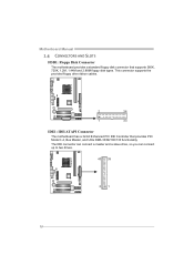
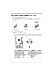
This connector supports the provided floppy drive ribbon cables. 2 34 1 33 IDE1: IDE/ATAPI Connector The motherboard has a 32-bit Enhanced PCI IDE Controller that supports 360K, 720K, 1.2M, 1.44M and 2.88M floppy disk types. Motherboard Manual 2.4 CONNECTORS AND SLOTS FDD1: Floppy Disk Connector The motherboard provides a standard floppy disk connector that provides PIO Mode 0~4, Bus Master, and Ultra DMA 33/66/100/133 functionality. The IDE connector can connect a master and a slave drive, so you can connect up to two drives. 40 39 2 1 10
This connector supports the provided floppy drive ribbon cables. 2 34 1 33 IDE1: IDE/ATAPI Connector The motherboard has a 32-bit Enhanced PCI IDE Controller that supports 360K, 720K, 1.2M, 1.44M and 2.88M floppy disk types. Motherboard Manual 2.4 CONNECTORS AND SLOTS FDD1: Floppy Disk Connector The motherboard provides a standard floppy disk connector that provides PIO Mode 0~4, Bus Master, and Ultra DMA 33/66/100/133 functionality. The IDE connector can connect a master and a slave drive, so you can connect up to two drives. 40 39 2 1 10
Setup Manual
Page 13
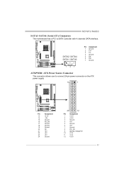
... Ground 5 RX6 RX+ 7 Ground 14 7 ATXPWR1: ATX Power Source Connector This connector allows user to SATA Controller with 4 channels SATA interface. MCP6P3/N68S3 SATA1~SATA4: Serial ATA Connectors The motherboard has a PCI to connect 24-pin power connector on the ATX power supply. 13 1 Pin Assignment 13 +3.3V 14 -12V 15 Ground...
... Ground 5 RX6 RX+ 7 Ground 14 7 ATXPWR1: ATX Power Source Connector This connector allows user to SATA Controller with 4 channels SATA interface. MCP6P3/N68S3 SATA1~SATA4: Serial ATA Connectors The motherboard has a PCI to connect 24-pin power connector on the ATX power supply. 13 1 Pin Assignment 13 +3.3V 14 -12V 15 Ground...

Setup Manual
Page 14
Motherboard Manual ATXPWR2: ATX Power Source Connector Connecting this connector provides +12V to CPU power circuit. 1 4 2 3 Pin Assignment 1 +12V 2 +12V 3 Ground 4 Ground Note: Before you power ...
Motherboard Manual ATXPWR2: ATX Power Source Connector Connecting this connector provides +12V to CPU power circuit. 1 4 2 3 Pin Assignment 1 +12V 2 +12V 3 Ground 4 Ground Note: Before you power ...
Setup Manual
Page 15
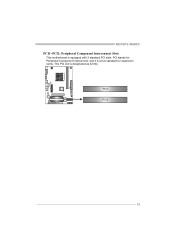
PCI stands for Peripheral Component Interconnect, and it is equipped with 2 standard PCI slots. MCP6P3/N68S3 PCI1~PCI2: Peripheral Component Interconnect Slots This motherboard is a bus standard for expansion cards. PCI1 PCI2 13 This PCI slot is designated as 32 bits.
PCI stands for Peripheral Component Interconnect, and it is equipped with 2 standard PCI slots. MCP6P3/N68S3 PCI1~PCI2: Peripheral Component Interconnect Slots This motherboard is a bus standard for expansion cards. PCI1 PCI2 13 This PCI slot is designated as 32 bits.
Setup Manual
Page 16
... closed Pin1-2 closed 3.2 DETAIL SETTINGS PANEL1: Front Panel Header This 16-pin connector includes Power-on button 14 It allows user to set up jumpers. Motherboard Manual CHAPTER 3: HEADERS & JUMPERS SETUP 3.1 HOW TO SETUP JUMPERS The illustration shows how to connect the PC case's front panel switch functions. PWR_LED On/Off...
... closed Pin1-2 closed 3.2 DETAIL SETTINGS PANEL1: Front Panel Header This 16-pin connector includes Power-on button 14 It allows user to set up jumpers. Motherboard Manual CHAPTER 3: HEADERS & JUMPERS SETUP 3.1 HOW TO SETUP JUMPERS The illustration shows how to connect the PC case's front panel switch functions. PWR_LED On/Off...
Setup Manual
Page 17
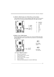
... on the PC front panel, and also can be connected with internal USB devices, like USB card reader. MCP6P3/N68S3 F_USB1/F_USB2: Headers for five seconds. 4. Set the jumper to avoid damaging the motherboard. 13 13 Pin 1-2 Close: Normal Operation (default). 13 Pin 2-3 Close: Clear CMOS data. ※ Clear CMOS Procedures: 1. F_USB2...
... on the PC front panel, and also can be connected with internal USB devices, like USB card reader. MCP6P3/N68S3 F_USB1/F_USB2: Headers for five seconds. 4. Set the jumper to avoid damaging the motherboard. 13 13 Pin 1-2 Close: Normal Operation (default). 13 Pin 2-3 Close: Clear CMOS data. ※ Clear CMOS Procedures: 1. F_USB2...

Setup Manual
Page 18
This header allows only HD audio front panel connector; AC'97 connector is not acceptable. 2 10 1 9 Pin Assignment 1 Mic Left in 2 Ground 3 Mic Right in 4 GPIO 5 Right line in 6 Jack Sense 7 Front Sense 8 Key 9 Left line in 10 Jack Sense JSPDIFOUT1: Digital Audio-out Connector This connector allows user to connect the front audio output cable with the PC front panel. Motherboard Manual F_AUDIO1: Front Panel Audio Header This header allows user to connect the PCI bracket SPDIF output header. 13 Pin Assignment 1 +5V 2 SPDIF_OUT 3 Ground 16
This header allows only HD audio front panel connector; AC'97 connector is not acceptable. 2 10 1 9 Pin Assignment 1 Mic Left in 2 Ground 3 Mic Right in 4 GPIO 5 Right line in 6 Jack Sense 7 Front Sense 8 Key 9 Left line in 10 Jack Sense JSPDIFOUT1: Digital Audio-out Connector This connector allows user to connect the front audio output cable with the PC front panel. Motherboard Manual F_AUDIO1: Front Panel Audio Header This header allows user to connect the PCI bracket SPDIF output header. 13 Pin Assignment 1 +5V 2 SPDIF_OUT 3 Ground 16

Setup Manual
Page 20
JUSBV2: +5V STB for USB ports at F_USB1/F_USB2. JUSBV1 3 1 3 1 JUSBV2 3 1 Pin 1-2 close 3 1 Pin 2-3 close JKB_PWR: Power Source Header for PS/2 Keyboard and Mouse 3 3 1 1 Pin 1-2 close +5V for PS/2 keyboard and mouse. 3 1 Pin 2-3 close +5V STB for PS/2 keyboard and mouse. 18 JUSBV2: +5V for USB ports at F_USB1/F_USB2. Pin 2-3 Close: JUSBV1: +5V STB for USB ports at USB1/RJ45USB1. Motherboard Manual JUSBV1/JUSBV2: Power Source Headers for USB Ports Pin 1-2 Close: JUSBV1: +5V for USB ports at USB1/RJ45USB1.
JUSBV2: +5V STB for USB ports at F_USB1/F_USB2. JUSBV1 3 1 3 1 JUSBV2 3 1 Pin 1-2 close 3 1 Pin 2-3 close JKB_PWR: Power Source Header for PS/2 Keyboard and Mouse 3 3 1 1 Pin 1-2 close +5V for PS/2 keyboard and mouse. 3 1 Pin 2-3 close +5V STB for PS/2 keyboard and mouse. 18 JUSBV2: +5V for USB ports at F_USB1/F_USB2. Pin 2-3 Close: JUSBV1: +5V STB for USB ports at USB1/RJ45USB1. Motherboard Manual JUSBV1/JUSBV2: Power Source Headers for USB Ports Pin 1-2 Close: JUSBV1: +5V for USB ports at USB1/RJ45USB1.
Setup Manual
Page 22
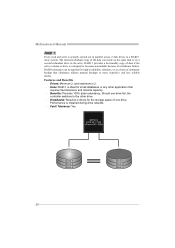
... Benefits Drives: Minimum 2, and maximum is 2. Uses: RAID 1 is actually carried out in parallel across 2 disk drives in the array. Should one drive. Motherboard Manual RAID 1: Every read and write is ideal for small databases or any other drive. Drawbacks: Requires 2 drives for high-availability solutions, or as...
... Benefits Drives: Minimum 2, and maximum is 2. Uses: RAID 1 is actually carried out in parallel across 2 disk drives in the array. Should one drive. Motherboard Manual RAID 1: Every read and write is ideal for small databases or any other drive. Drawbacks: Requires 2 drives for high-availability solutions, or as...

Setup Manual
Page 24
Motherboard Manual RAID 5: RAID 5 stripes both data and parity information across all the drives in the array. Disk 1 DATA 1 DATA 3 PARITY DATA 7 DATA 9 PARITY GeForce 6150 ...
Motherboard Manual RAID 5: RAID 5 stripes both data and parity information across all the drives in the array. Disk 1 DATA 1 DATA 3 PARITY DATA 7 DATA 9 PARITY GeForce 6150 ...
Setup Manual
Page 25
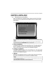
MCP6P3/N68S3 CHAPTER 5: USEFUL HELP 5.1 DRIVER INSTALLATION NOTE After you insert the CD The setup guide will auto detect your motherboard and operating system. A. The setup guide will see the following window after you insert the Driver CD, please use file browser to... program. Note: If this window didn't show up after you installed your operating system, please insert the Fully Setup Driver CD into your motherboard and operating system. Click on the Software icon. The setup guide will need Acrobat Reader to launch the installation program. B. Click on each...
MCP6P3/N68S3 CHAPTER 5: USEFUL HELP 5.1 DRIVER INSTALLATION NOTE After you insert the CD The setup guide will auto detect your motherboard and operating system. A. The setup guide will see the following window after you insert the Driver CD, please use file browser to... program. Note: If this window didn't show up after you installed your operating system, please insert the Fully Setup Driver CD into your motherboard and operating system. Click on the Software icon. The setup guide will need Acrobat Reader to launch the installation program. B. Click on each...
Setup Manual
Page 26
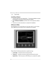
Transform:Transform the picture for BIOS and preview the result. 3. Motherboard Manual 5.2 SOFTWARE Installing Software 1. Update Bios:Write the picture to BIOS Memory to complete the installation. Follow the on the respective software title. 3. BIOScreen ...
Transform:Transform the picture for BIOS and preview the result. 3. Motherboard Manual 5.2 SOFTWARE Installing Software 1. Update Bios:Write the picture to BIOS Memory to complete the installation. Follow the on the respective software title. 3. BIOScreen ...
Setup Manual
Page 27
...reveal the malfunctioning card. If the video adapter is an add-in card, replace or 8 reseat the video adapter. Before declaring the motherboard beyond all other expansion cards are used for recovery 4 Flash Programming successful 5 File read error 7 No Flash EPROM detected 10 Flash Erase...is causing the malfunction. If the system video adapter is an integrated part of the system board, the board may be faulty. 25 MCP6P3/N68S3 5.3 AMI BIOS BEEP CODE Boot Block Beep Codes Number of Beeps Description 1 No media present. (Insert diskette in floppy drive A:) 2...
...reveal the malfunctioning card. If the video adapter is an add-in card, replace or 8 reseat the video adapter. Before declaring the motherboard beyond all other expansion cards are used for recovery 4 Flash Programming successful 5 File read error 7 No Flash EPROM detected 10 Flash Erase...is causing the malfunction. If the system video adapter is an integrated part of the system board, the board may be faulty. 25 MCP6P3/N68S3 5.3 AMI BIOS BEEP CODE Boot Block Beep Codes Number of Beeps Description 1 No media present. (Insert diskette in floppy drive A:) 2...

Setup Manual
Page 28
... a damage of the CPU, and the system may not power on the system again. 26 Plug in the power cord and boot up the system. Motherboard Manual 5.4 EXTRA INFORMATION CPU Overheated If the system shutdown automatically after power on system for seconds. 2. In this case, please double check: 1. The CPU cooler...
... a damage of the CPU, and the system may not power on the system again. 26 Plug in the power cord and boot up the system. Motherboard Manual 5.4 EXTRA INFORMATION CPU Overheated If the system shutdown automatically after power on system for seconds. 2. In this case, please double check: 1. The CPU cooler...


