
M7VKG user's manual
Page 3
... 1-2 1.1.1 Hardware 1-2 1.1.2 Software 1-5 1.1.3 Attachments 1-5 1.2 Motherboard Installation 1-6 1.2.1 Layout of Motherboard 1-6 1.3 Motherboard Quick Reference 1-7 1.3.1 Front Panel Connectors (JPANEL1 / JPANEL2 1-8 1.3.2 Floppy Disk Connector (FDD1 1-10 1.3.3 Hard Disk Connectors (IDE1/IDE2 1-10 1.3.4 ATX 20-pin Power Connector (JATXPWR1 1-11 1.4 ...
... 1-2 1.1.1 Hardware 1-2 1.1.2 Software 1-5 1.1.3 Attachments 1-5 1.2 Motherboard Installation 1-6 1.2.1 Layout of Motherboard 1-6 1.3 Motherboard Quick Reference 1-7 1.3.1 Front Panel Connectors (JPANEL1 / JPANEL2 1-8 1.3.2 Floppy Disk Connector (FDD1 1-10 1.3.3 Hard Disk Connectors (IDE1/IDE2 1-10 1.3.4 ATX 20-pin Power Connector (JATXPWR1 1-11 1.4 ...
M7VKG user's manual
Page 6
Chapter 1 Motherboard Description Introduction System Overview Thanks for buying this product as quickly and smoothly as possible. This manual was written to help you will find adequate ...
Chapter 1 Motherboard Description Introduction System Overview Thanks for buying this product as quickly and smoothly as possible. This manual was written to help you will find adequate ...
M7VKG user's manual
Page 7
Chapter 1 Motherboard Description 1. Green Function − Support power management operation via BIOS. − Power down timer from 1 to 15 mins. − Wakes from power saving sleep mode .../32/64/128/256/512MB DIMM module socket. − Supports Synchronous DRAM (3.3V). − Support a maximum memory size of any key or any mouse activity. Motherboard Description 1.1 Features 1.1.1 Hardware CPU − Single AMD Socket-A for Athlon TM (Thunderbird TM ) / Duron TM processor Module-500MHz ~ 1.2GHz. − 200/266 MHz Front Side...
Chapter 1 Motherboard Description 1. Green Function − Support power management operation via BIOS. − Power down timer from 1 to 15 mins. − Wakes from power saving sleep mode .../32/64/128/256/512MB DIMM module socket. − Supports Synchronous DRAM (3.3V). − Support a maximum memory size of any key or any mouse activity. Motherboard Description 1.1 Features 1.1.1 Hardware CPU − Single AMD Socket-A for Athlon TM (Thunderbird TM ) / Duron TM processor Module-500MHz ~ 1.2GHz. − 200/266 MHz Front Side...
M7VKG user's manual
Page 8
... 10 band graphic equalizer. − Sound Blaster® and Sound Blaster Pro® emulation. − 64-voice wavetable. − PC99 complaint and WHQL certified. Chapter 1 Motherboard Description − Provides CNR (Modem function only) slot . IDE Built-in On Board − Supports one multi-mode Parallel Port. (1) Standard & Bidirection Parallel Port. (2) Enhanced...
... 10 band graphic equalizer. − Sound Blaster® and Sound Blaster Pro® emulation. − 64-voice wavetable. − PC99 complaint and WHQL certified. Chapter 1 Motherboard Description − Provides CNR (Modem function only) slot . IDE Built-in On Board − Supports one multi-mode Parallel Port. (1) Standard & Bidirection Parallel Port. (2) Enhanced...

M7VKG user's manual
Page 9
... generation, 128-bit 2D graphics engine. − High quality DVD video playback. − Flat panel monitor support. − 2D/3D resolutions up to 1920x1440. 1-4 Chapter 1 Motherboard Description Universal Serial Bus − Supports two back Universal Serial Bus (USB) Ports and two front Universal serial Bus (USB) Ports (Optional). − Supports 48...
... generation, 128-bit 2D graphics engine. − High quality DVD video playback. − Flat panel monitor support. − 2D/3D resolutions up to 1920x1440. 1-4 Chapter 1 Motherboard Description Universal Serial Bus − Supports two back Universal Serial Bus (USB) Ports and two front Universal serial Bus (USB) Ports (Optional). − Supports 48...

M7VKG user's manual
Page 10
... Driver CD. For 1.2GHz CPU, we recommend the user to add a "Chipset Fan" in order to reduce the excess thermal dissipated from Northbridge Chipset. 1-5 Chapter 1 Motherboard Description 1.1.2 Software BIOS − AWARD legal BIOS. − Supports APM1.2. − Supports USB Function. − Supports ACPI.
... Driver CD. For 1.2GHz CPU, we recommend the user to add a "Chipset Fan" in order to reduce the excess thermal dissipated from Northbridge Chipset. 1-5 Chapter 1 Motherboard Description 1.1.2 Software BIOS − AWARD legal BIOS. − Supports APM1.2. − Supports USB Function. − Supports ACPI.

M7VKG user's manual
Page 11
Chapter 1 Motherboard Description 1.2 Motherboard Installation 1.2.1 Layout of Motherboard Model No.M7VKG 1-6
Chapter 1 Motherboard Description 1.2 Motherboard Installation 1.2.1 Layout of Motherboard Model No.M7VKG 1-6
M7VKG user's manual
Page 12
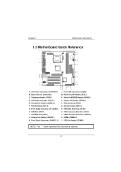
... Ratio Selection (JCLK2) S. Telephony Header (JTAD1) D. Wake-On MODEM Header (JWOM1*) O. System Fan Header (JSFAN1) P. CNR Slot (CNR1) I /O Connectors C. Wake-On-LAN Header (JWOL1) N. Chapter 1 Motherboard Description 1.3 Motherboard Quick Reference A V U T S R B P C E F G N H M A. Front Panel Connector (JPANEL1-2) IJ K L L. CMOS Function Selection (JCMOS1) U. Chipset Fan Header (JSFAN3*) K. CD Audio-In Header (JCDIN1-2) F. CPU Frequency Selection (JCLK1...
... Ratio Selection (JCLK2) S. Telephony Header (JTAD1) D. Wake-On MODEM Header (JWOM1*) O. System Fan Header (JSFAN1) P. CNR Slot (CNR1) I /O Connectors C. Wake-On-LAN Header (JWOL1) N. Chapter 1 Motherboard Description 1.3 Motherboard Quick Reference A V U T S R B P C E F G N H M A. Front Panel Connector (JPANEL1-2) IJ K L L. CMOS Function Selection (JCMOS1) U. Chipset Fan Header (JSFAN3*) K. CD Audio-In Header (JCDIN1-2) F. CPU Frequency Selection (JCLK1...
M7VKG user's manual
Page 13
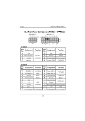
... Sleep Control 12 Ground SLP Button 14 No Connection No Connection 16 +5V VCC 17 No Connection No Connection 18 No Connection No Connection 1-8 Chapter 1 Motherboard Description 1.3.1 Front Panel Connectors (JPANEL1 / JPANEL2) JPANEL1 JPANEL2 V G NC PWR-LED PWR-LED PWR 2 82 1 71 SPK HLED RST SLP NC V NC 18 17 IR...
... Sleep Control 12 Ground SLP Button 14 No Connection No Connection 16 +5V VCC 17 No Connection No Connection 18 No Connection No Connection 1-8 Chapter 1 Motherboard Description 1.3.1 Front Panel Connectors (JPANEL1 / JPANEL2) JPANEL1 JPANEL2 V G NC PWR-LED PWR-LED PWR 2 82 1 71 SPK HLED RST SLP NC V NC 18 17 IR...

M7VKG user's manual
Page 14
...from or to the onboard hard drive controller. Infrared Connector After the IrDA interface is being read from or written to the motherboard at the front panel connector. Closing the SMI switch sends a System Management Interrupt (SMI) to the processor, which must be... software. Hard Drive LED Connector This connector can be connected to and servicing external interrupts (such as a manufacturing option. Chapter 1 Motherboard Description Speaker Connector An offboard speaker can be installed on . Power LED Connector This connector can be a momentary SPST type that will...
...from or to the onboard hard drive controller. Infrared Connector After the IrDA interface is being read from or written to the motherboard at the front panel connector. Closing the SMI switch sends a System Management Interrupt (SMI) to the processor, which must be... software. Hard Drive LED Connector This connector can be connected to and servicing external interrupts (such as a manufacturing option. Chapter 1 Motherboard Description Speaker Connector An offboard speaker can be installed on . Power LED Connector This connector can be a momentary SPST type that will...

M7VKG user's manual
Page 15
...connect up to four hard disk drives, a CD-ROM, a 120MB Floppy (reserved for future BIOS) and other devices to IDE1. Chapter 1 Motherboard Description Power On Button This connector can connect a Master and a Slave drive. The configuration is due to IDE1. This connector supports the provided ...floppy drive ribbon cables. 1.3.3 Hard Disk Connectors (IDE1/IDE2) The motherboard has a 32-bit Enhanced PCI IDE Controller that supports 360K, 720K, 1.2M, 1.44M and 2.88M floppy disk types. It has two HDD ...
...connect up to four hard disk drives, a CD-ROM, a 120MB Floppy (reserved for future BIOS) and other devices to IDE1. Chapter 1 Motherboard Description Power On Button This connector can connect a Master and a Slave drive. The configuration is due to IDE1. This connector supports the provided ...floppy drive ribbon cables. 1.3.3 Hard Disk Connectors (IDE1/IDE2) The motherboard has a 32-bit Enhanced PCI IDE Controller that supports 360K, 720K, 1.2M, 1.44M and 2.88M floppy disk types. It has two HDD ...

M7VKG user's manual
Page 16
This power connector supports instant power-on functionality, which means that the system will boot up instantly when the power connector is inserted on this motherboard. Using the ATX power supply, functions such as Modem Ring Wake-Up and Soft Power Off are supported on the board. Pin No. 1 2 3 4 5 6 7 8 9 10 Assignment +3.... Pin No. 11 12 13 14 15 16 17 18 19 20 Assignment +3.3V -12V Ground PS_ON Ground Ground Ground -5V +5V +5V 1-11 Chapter 1 Motherboard Description 1.3.4 ATX 20-pin Power Connector (JATXPWR1) This connector supports the power button on-board.
This power connector supports instant power-on functionality, which means that the system will boot up instantly when the power connector is inserted on this motherboard. Using the ATX power supply, functions such as Modem Ring Wake-Up and Soft Power Off are supported on the board. Pin No. 1 2 3 4 5 6 7 8 9 10 Assignment +3.... Pin No. 11 12 13 14 15 16 17 18 19 20 Assignment +3.3V -12V Ground PS_ON Ground Ground Ground -5V +5V +5V 1-11 Chapter 1 Motherboard Description 1.3.4 ATX 20-pin Power Connector (JATXPWR1) This connector supports the power button on-board.
M7VKG user's manual
Page 17
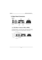
... JUSB1 CN2 Parallel U14 Game Port PS/2 USB Keyboard COM1 CN1 VGA1 CN3 Speaker Line Mic out in in 1.4.1 PS/2 Mouse / Keyboard CONN.: JKBMS1 The motherboard provides a standard PS/2 mouse / Keyboard mini DIN connector for attaching a PS/2 mouse. The connector location and pin definition are shown below: PS / 2 Mouse Pin 6 NC...
... JUSB1 CN2 Parallel U14 Game Port PS/2 USB Keyboard COM1 CN1 VGA1 CN3 Speaker Line Mic out in in 1.4.1 PS/2 Mouse / Keyboard CONN.: JKBMS1 The motherboard provides a standard PS/2 mouse / Keyboard mini DIN connector for attaching a PS/2 mouse. The connector location and pin definition are shown below: PS / 2 Mouse Pin 6 NC...

M7VKG user's manual
Page 18
Chapter 1 Motherboard Description PS/2 Mouse / Keyboard Connectors Pin No. 1 2 3 4 5 6 Signal Name Data No connection Ground +5 V (fused) Clock No connection 1.4.2 USB Connector: JUSB1 The motherboard provides a OHCI (Open Host Controller Interface) Universal Serial Bus Roots for USB Port 1. 1-13 JUSB1 USB 12 34 1234 Stacked USB Connectors Pin No. 1 2 Assignment +5 V USBP0- [USBP1-] 3 USBP0+ [USBP1+] 4 Ground Signal names in brackets ([]) are for attaching USB devices such as: keyboard, mouse and other USB device.
Chapter 1 Motherboard Description PS/2 Mouse / Keyboard Connectors Pin No. 1 2 3 4 5 6 Signal Name Data No connection Ground +5 V (fused) Clock No connection 1.4.2 USB Connector: JUSB1 The motherboard provides a OHCI (Open Host Controller Interface) Universal Serial Bus Roots for USB Port 1. 1-13 JUSB1 USB 12 34 1234 Stacked USB Connectors Pin No. 1 2 Assignment +5 V USBP0- [USBP1-] 3 USBP0+ [USBP1+] 4 Ground Signal names in brackets ([]) are for attaching USB devices such as: keyboard, mouse and other USB device.

M7VKG user's manual
Page 19
Chapter 1 Motherboard Description 1.4.3 Monitor Connector: JVGA1 This motherboard has built in video facilities. Your monitor will attach directly to JVGA1 connector on the motherboard. 5 1 15 11 JVGA1 Pin No. Assignment Pin No. Assignment 1 Red 2 Green 3 Blue 4 +5V 5 Ground 6 Ground 7 Ground 8 Ground 9 +5V 10 Ground 11 +5V 12 DDC/Data 13 HSYNC 14 VSYNC 15 DDC/CLK 1-14
Chapter 1 Motherboard Description 1.4.3 Monitor Connector: JVGA1 This motherboard has built in video facilities. Your monitor will attach directly to JVGA1 connector on the motherboard. 5 1 15 11 JVGA1 Pin No. Assignment Pin No. Assignment 1 Red 2 Green 3 Blue 4 +5V 5 Ground 6 Ground 7 Ground 8 Ground 9 +5V 10 Ground 11 +5V 12 DDC/Data 13 HSYNC 14 VSYNC 15 DDC/CLK 1-14
M7VKG user's manual
Page 20
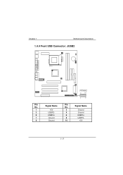
Chapter 1 Motherboard Description 1.4.4 Front USB Connector: JUSB2 JUSB2 2 10 19 Pin No. Signal Name 1 +5V 2 Ground 3 USBP2- 4 Ground 5 USBP2+ 6 USBP3+ 7 Ground 8 USBP3- 9 Ground 10 +5V 1-15 Signal Name Pin No.
Chapter 1 Motherboard Description 1.4.4 Front USB Connector: JUSB2 JUSB2 2 10 19 Pin No. Signal Name 1 +5V 2 Ground 3 USBP2- 4 Ground 5 USBP2+ 6 USBP3+ 7 Ground 8 USBP3- 9 Ground 10 +5V 1-15 Signal Name Pin No.
M7VKG user's manual
Page 21
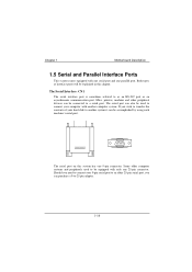
...-232 port or an asynchronous communication port. Mice, printers, modems and other peripheral devices can also be accomplished by using each machine's serial port. Chapter 1 Motherboard Description 1.5 Serial and Parallel Interface Ports This system comes equipped with only one 9-pin connector.
...-232 port or an asynchronous communication port. Mice, printers, modems and other peripheral devices can also be accomplished by using each machine's serial port. Chapter 1 Motherboard Description 1.5 Serial and Parallel Interface Ports This system comes equipped with only one 9-pin connector.
M7VKG user's manual
Page 22
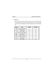
... pin on the 9-pin connector and some of the 25-pin connector. This information can be necessary to become familiar with the serial port. Chapter 1 Motherboard Description Connectivity The serial port can be used in many ways, and it may be used when configuring certain software programs to work with the...
... pin on the 9-pin connector and some of the 25-pin connector. This information can be necessary to become familiar with the serial port. Chapter 1 Motherboard Description Connectivity The serial port can be used in many ways, and it may be used when configuring certain software programs to work with the...
M7VKG user's manual
Page 23
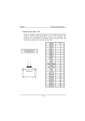
... called Centronics port, the parallel port is almost exclusively used with printers. The pinouts for the parallel port are shown in the table below ). Chapter 1 Motherboard Description Parallel Interface Port : CN2 Unlike the serial port, parallel interface port has been standardized and should not present any difficulty interfacing peripherals to your...
... called Centronics port, the parallel port is almost exclusively used with printers. The pinouts for the parallel port are shown in the table below ). Chapter 1 Motherboard Description Parallel Interface Port : CN2 Unlike the serial port, parallel interface port has been standardized and should not present any difficulty interfacing peripherals to your...

M7VKG user's manual
Page 24
Press the lever down to a 90-degree angle. 2. Chapter 1 Motherboard Description 1.6 CPU Installation 1.6.1 CPU Installation Procedure: Socket A Socket A 1. Pull the lever sideways away from the socket then raise the lever up to complete the installation. 1-19 Match Pin A with the white dot/cut edge in the socket and look for the white dot or cut edge then insert the CPU. 3. Locate Pin A in the CPU.
Press the lever down to a 90-degree angle. 2. Chapter 1 Motherboard Description 1.6 CPU Installation 1.6.1 CPU Installation Procedure: Socket A Socket A 1. Pull the lever sideways away from the socket then raise the lever up to complete the installation. 1-19 Match Pin A with the white dot/cut edge in the socket and look for the white dot or cut edge then insert the CPU. 3. Locate Pin A in the CPU.

