
M7VIT user's manual
Page 3
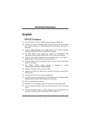
...maximun memory size up to Bass/ Center Out by Audio Utility.) (Optional) 1 Line-in phonejack and Mic-in Front Panel. Supports Single Socket-A for 6 channels Audio. 6-Channel Hardware Audio or Codec. (Change Line-In to Back-Audio Out and Mic-In to 3GB. CPU over...in Rear Panel and 4 ports in jack share with PC ATX form factor specifications. Intel® AC'97 2.2 compatible. MMootthheerrbbooaarrdd DDeessccrriippttiioonn English M7VIT Features Use VIA VT8377 (KT400)/ VT8235 Chipset, Winbond W83697HF. Supports popular operating systems such as Windows NT, Windows 98SE, Windows 2000, ...
...maximun memory size up to Bass/ Center Out by Audio Utility.) (Optional) 1 Line-in phonejack and Mic-in Front Panel. Supports Single Socket-A for 6 channels Audio. 6-Channel Hardware Audio or Codec. (Change Line-In to Back-Audio Out and Mic-In to 3GB. CPU over...in Rear Panel and 4 ports in jack share with PC ATX form factor specifications. Intel® AC'97 2.2 compatible. MMootthheerrbbooaarrdd DDeessccrriippttiioonn English M7VIT Features Use VIA VT8377 (KT400)/ VT8235 Chipset, Winbond W83697HF. Supports popular operating systems such as Windows NT, Windows 98SE, Windows 2000, ...

M7VIT user's manual
Page 5
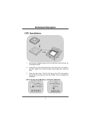
MMootthheerrbbooaarrdd DDeessccrriippttiioonn Layout of M7VIT 1 JKBV1 1 JUSBV1 CPU MIC-IN LINE-IN SP-OUT GAME Port Socket A 1 JATXPWR1 VT8377 (KT400) 1 JGAME1 JAUDIO1 Winbond I/O 1 AGP SLOT PCI1 IDE1 IDE2 BAT1 BIOS Codec PCI SLOT 1 PCI SLOT PCI SLOT Hardware Audio PCI SLOT PCI SLOT CNR1 CNR SLOT 4 6 PCI2 1 3 JUSB2 2 10 PCI3 1 9 VT8235 JUSB3 2 10 PCI4 19 1 JUSBV2 1 JCMOS1 PCI5 FDD1 JWOL1 1 1 JPANEL1 2 24 1 23 JSFAN1 3
MMootthheerrbbooaarrdd DDeessccrriippttiioonn Layout of M7VIT 1 JKBV1 1 JUSBV1 CPU MIC-IN LINE-IN SP-OUT GAME Port Socket A 1 JATXPWR1 VT8377 (KT400) 1 JGAME1 JAUDIO1 Winbond I/O 1 AGP SLOT PCI1 IDE1 IDE2 BAT1 BIOS Codec PCI SLOT 1 PCI SLOT PCI SLOT Hardware Audio PCI SLOT PCI SLOT CNR1 CNR SLOT 4 6 PCI2 1 3 JUSB2 2 10 PCI3 1 9 VT8235 JUSB3 2 10 PCI4 19 1 JUSBV2 1 JCMOS1 PCI5 FDD1 JWOL1 1 1 JPANEL1 2 24 1 23 JSFAN1 3
M7VIT user's manual
Page 6
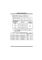
MMootthheerrbbooaarrdd DDeessccrriippttiioonn CPU Installation CPU 1. Then Put the fan on the CPU and buckle it and put the fan's power port into the JCFAN1, then to 90-degree angle. 2. CPU/ System Fan Headers: JCFAN1/ JSFAN1 Sense 12V 1 Ground 12V Ground Sense JCFAN1 JSFAN1 4 Match Pin A with the white dot/cut edge in the CPU. Locate Pin A in the socket and lock for the white dot or cut edge then insert the CPU. 3. Pull the lever sideways away from the socket then raise the lever up to complete the installation. Press the lever down.
MMootthheerrbbooaarrdd DDeessccrriippttiioonn CPU Installation CPU 1. Then Put the fan on the CPU and buckle it and put the fan's power port into the JCFAN1, then to 90-degree angle. 2. CPU/ System Fan Headers: JCFAN1/ JSFAN1 Sense 12V 1 Ground 12V Ground Sense JCFAN1 JSFAN1 4 Match Pin A with the white dot/cut edge in the CPU. Locate Pin A in the socket and lock for the white dot or cut edge then insert the CPU. 3. Pull the lever sideways away from the socket then raise the lever up to complete the installation. Press the lever down.
M7VIT user's manual
Page 7
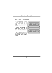
...: DIMM1-2-3 DRAM Access Time: 2.5V Unbuffered/ Registered DDR 1600/ 2100/ 2700/ 3200 Type required. If use FSB333MHz CPU, the Memory support only DDR333 (PC2700). DIMM Socket Location DDR Module Total Memory Size (MB) DIMM 1 64MB/128MB/256MB/512MB/1GB *1 DIMM 2 64MB/128MB/256MB/512MB/1GB *1 Max is 3GB DIMM3 64MB/128MB...
...: DIMM1-2-3 DRAM Access Time: 2.5V Unbuffered/ Registered DDR 1600/ 2100/ 2700/ 3200 Type required. If use FSB333MHz CPU, the Memory support only DDR333 (PC2700). DIMM Socket Location DDR Module Total Memory Size (MB) DIMM 1 64MB/128MB/256MB/512MB/1GB *1 DIMM 2 64MB/128MB/256MB/512MB/1GB *1 Max is 3GB DIMM3 64MB/128MB...
M7VIT user's manual
Page 8
The Mounting Holes and plastic tabs should fit over the edge and hold the DIMM memory modules in one direction. 2. Push the tabs out. MMootthheerrbbooaarrdd DDeessccrriippttiioonn How to install a DIMM Module 1. Insert the DIMM memory modules into the socket at a 90-degree angle, then push down vertically so that it will fit into the slot in place. 6 The DIMM socket has a " Plastic Safety Tab", and the DIMM memory module has an "Asymmetrical notch", so the DIMM memory module can only fit into the place. 3.
The Mounting Holes and plastic tabs should fit over the edge and hold the DIMM memory modules in one direction. 2. Push the tabs out. MMootthheerrbbooaarrdd DDeessccrriippttiioonn How to install a DIMM Module 1. Insert the DIMM memory modules into the socket at a 90-degree angle, then push down vertically so that it will fit into the slot in place. 6 The DIMM socket has a " Plastic Safety Tab", and the DIMM memory module has an "Asymmetrical notch", so the DIMM memory module can only fit into the place. 3.

M7VIT compatibility test report
Page 4
...134; RIMM . † VCM † SDRAM † RDRAM ; Yes † No CPU Supports Type Socket A Socket A Socket A Socket A Socket A CPU AMD Athlon AMD Athlon AMD Athlon XP AMD Athlon XP AMD Duron CPU Frequency Max =1400Mhz Max =... RDRAM (MB) ; No 4 No ; PRODUCT INFORMATION Vendor Motherboard General Information Biostar Model Number Version Number Platform System Chipset Vendor North Bridge Revision South Bridge Revision ...Vendor RAID Chipset Revision BIOS Vendor BIOS Revision Number BIOS Memory Size Flash EPROM BIOS M7VIT V0.90/V0.91/V3.0 † AT ; DDR RAM † Yes ...
...134; RIMM . † VCM † SDRAM † RDRAM ; Yes † No CPU Supports Type Socket A Socket A Socket A Socket A Socket A CPU AMD Athlon AMD Athlon AMD Athlon XP AMD Athlon XP AMD Duron CPU Frequency Max =1400Mhz Max =... RDRAM (MB) ; No 4 No ; PRODUCT INFORMATION Vendor Motherboard General Information Biostar Model Number Version Number Platform System Chipset Vendor North Bridge Revision South Bridge Revision ...Vendor RAID Chipset Revision BIOS Vendor BIOS Revision Number BIOS Memory Size Flash EPROM BIOS M7VIT V0.90/V0.91/V3.0 † AT ; DDR RAM † Yes ...

M7VIT compatibility test report
Page 5
... Board Dimensions Visual Inspection of Soldering Visual Inspection of Layout Screw Holes Line Up with Case Power Connector placement in PCB DIMM/RIMM Socket placement in PCB CPU Socket placement in PCB FAN Connector placement in PCB FDD Connector placement in PCB IDE Connector placement in PCB Front Panel Connectors in PCB...
... Board Dimensions Visual Inspection of Soldering Visual Inspection of Layout Screw Holes Line Up with Case Power Connector placement in PCB DIMM/RIMM Socket placement in PCB CPU Socket placement in PCB FAN Connector placement in PCB FDD Connector placement in PCB IDE Connector placement in PCB Front Panel Connectors in PCB...


