

M7SXD user's manual
Page 7
...− SiS 645/ SiS 961. − Winbond W83697HF. Supports the Intel Pentium® 4 processor providing the new generation power for SDRAM 1-2 DRAM Memory − Supports 200MHz, 266MHz or 333MHz DDR SDRAM devices. − Supports 128MB, 256MB ,512MB and 1GB technologies for DDR SDRAM. − Max of... 2 Double-Sided DIMMs with unbuffer PC2100/ PC1600/ PC2700 for DDR SDRAM (without ECC). − The largest memory capacity is 2 GB for DDR SDRAM. − Supports 100MHz or 133MHz SDRAM devices. − Supports 128MB, 256MB, 512MB technologies for SDRAM. &#...
...− SiS 645/ SiS 961. − Winbond W83697HF. Supports the Intel Pentium® 4 processor providing the new generation power for SDRAM 1-2 DRAM Memory − Supports 200MHz, 266MHz or 333MHz DDR SDRAM devices. − Supports 128MB, 256MB ,512MB and 1GB technologies for DDR SDRAM. − Max of... 2 Double-Sided DIMMs with unbuffer PC2100/ PC1600/ PC2700 for DDR SDRAM (without ECC). − The largest memory capacity is 2 GB for DDR SDRAM. − Supports 100MHz or 133MHz SDRAM devices. − Supports 128MB, 256MB, 512MB technologies for SDRAM. &#...

M7SXD user's manual
Page 8
Chapter 1 Motherboard Description Shadow RAM − Motherboard is equipped with a memory controller providing shadow RAM and support for PVD applications. 1-3 AC'97 Sound Codec Onboard − AC-LINK protocol compliance. − Compliant ... 15 minutes. BUS Slots − (1) AGP slot. − (1) CNR slot. − (1) ACR slot − (5) 32-bit PCI bus slots Flash Memory − Supports flash memory functionality. − Supports ESCD functionality. Green Functionality − Supports Award BIOS ™ power management functionality. − Has a power down timer from 1 to...
Chapter 1 Motherboard Description Shadow RAM − Motherboard is equipped with a memory controller providing shadow RAM and support for PVD applications. 1-3 AC'97 Sound Codec Onboard − AC-LINK protocol compliance. − Compliant ... 15 minutes. BUS Slots − (1) AGP slot. − (1) CNR slot. − (1) ACR slot − (5) 32-bit PCI bus slots Flash Memory − Supports flash memory functionality. − Supports ESCD functionality. Green Functionality − Supports Award BIOS ™ power management functionality. − Has a power down timer from 1 to...
M7SXD user's manual
Page 10
Chapter 1 Motherboard Description 1.1.2 BIOS − Award legal BIOS. − Supports APM1.2. − Supports USB Function. − Supports ACPI. − Update BIOS. 1.1.3 Software Operating System − Offers the highest performance for MS-DOS, Windows NT, Windows 2000, Windows 95/98, Windows ME, Windows XP, Novell, SCO UNIX etc. 1.1.4 Accessories − HDD Cable. − FDD Cable. − Flash Memory Writer for BIOS Update. − JUSB1/JUSB2 Cable (Optional). − Rear I/O Panel for ATX Case (Optional). − Fully Setup Driver CD. 1-5
Chapter 1 Motherboard Description 1.1.2 BIOS − Award legal BIOS. − Supports APM1.2. − Supports USB Function. − Supports ACPI. − Update BIOS. 1.1.3 Software Operating System − Offers the highest performance for MS-DOS, Windows NT, Windows 2000, Windows 95/98, Windows ME, Windows XP, Novell, SCO UNIX etc. 1.1.4 Accessories − HDD Cable. − FDD Cable. − Flash Memory Writer for BIOS Update. − JUSB1/JUSB2 Cable (Optional). − Rear I/O Panel for ATX Case (Optional). − Fully Setup Driver CD. 1-5

M7SXD user's manual
Page 16
DRAM Type: 128MB/ 256MB/ 512MB/ 1GB DIMM Module (184 pin) Total Memory Size with unbuffer DIMMs (Only for reference) Total Memory DIMM 1 DIMM 2 Size (MB) 128 M 128 M ---- 256 M 256 M ---- 512 M 512 M ---- 1 G 256 M 384 M 1G 128 M 256 M ---128 M 128 M 640 M 1128 M 384 M 512 M 1G 128 M 128 M 128 M ...
DRAM Type: 128MB/ 256MB/ 512MB/ 1GB DIMM Module (184 pin) Total Memory Size with unbuffer DIMMs (Only for reference) Total Memory DIMM 1 DIMM 2 Size (MB) 128 M 128 M ---- 256 M 256 M ---- 512 M 512 M ---- 1 G 256 M 384 M 1G 128 M 256 M ---128 M 128 M 640 M 1128 M 384 M 512 M 1G 128 M 128 M 128 M ...

M7SXD user's manual
Page 17
... Access Time: 3.3V Unbuffered SDRAM (without ECC) PC100/ PC133 Type required. DRAM Type: 128MB/ 256MB/ 512MB DIMM Module (168 pin) Total Memory Size with unbuffer DIMMs (Only for reference) Total Memory DIMM 1 DIMM 2 Size (MB) 128 M 256 M 512 M 256 M 128 M 256 M 512 M 128 M ---------128 M 384 M 640 M 256 M 512 M 128 M 128 M 384 M 512... M 768 M 128 M 256 M 512 M 256 M 256 M 256 M 640 M 768 M 1024 M 128 M 256 M 512 M 512 M 512 M 512 M When you use DDR SDRAM, the memory power will automatically set to 3.3V. For the above settings, you use one kind of...
... Access Time: 3.3V Unbuffered SDRAM (without ECC) PC100/ PC133 Type required. DRAM Type: 128MB/ 256MB/ 512MB DIMM Module (168 pin) Total Memory Size with unbuffer DIMMs (Only for reference) Total Memory DIMM 1 DIMM 2 Size (MB) 128 M 256 M 512 M 256 M 128 M 256 M 512 M 128 M ---------128 M 384 M 640 M 256 M 512 M 128 M 128 M 384 M 512... M 768 M 128 M 256 M 512 M 256 M 256 M 256 M 640 M 768 M 1024 M 128 M 256 M 512 M 512 M 512 M 512 M When you use DDR SDRAM, the memory power will automatically set to 3.3V. For the above settings, you use one kind of...

M7SXD user's manual
Page 18
Push the tabs out. The DDR DIMM socket has a " Plastic Safety Tab", and the DDR DIMM memory module has an Asymmetrical notch", so the DDR DIMM memory module can only fit into the place. 3. The Mounting Holes and plastic tabs should fit over the edge and hold the DDR DIMM memory modules in one direction. 2. Insert the DDR DIMM memory modules into the socket at a 90-degree angle, then push down vertically so that it will fit into the slot in place. 1-13 Chapter 1 Motherboard Description 1.4.3 How to install DDR/SDRAM DIMM Module DDR SDRAM: Single Sided DIMM Double Sided DIMM 1.
Push the tabs out. The DDR DIMM socket has a " Plastic Safety Tab", and the DDR DIMM memory module has an Asymmetrical notch", so the DDR DIMM memory module can only fit into the place. 3. The Mounting Holes and plastic tabs should fit over the edge and hold the DDR DIMM memory modules in one direction. 2. Insert the DDR DIMM memory modules into the socket at a 90-degree angle, then push down vertically so that it will fit into the slot in place. 1-13 Chapter 1 Motherboard Description 1.4.3 How to install DDR/SDRAM DIMM Module DDR SDRAM: Single Sided DIMM Double Sided DIMM 1.

M7SXD user's manual
Page 19
The SDRAM DIMM socket has a " Plastic Safety Tab", and the SDRAM DIMM memory module has an Asymmetrical notch", so the SDRAM DIMM memory module can only fit into the place. 3. The Mounting Holes and plastic tabs should fit over the edge and hold the SDRAM DIMM memory modules in one direction. 2. Insert the SDRAM DIMM memory modules into the socket at a 90-degree angle, then push down vertically so that it will fit into the slot in place. 1-14 Chapter 1 SDRAM: Motherboard Description 1. Push the tabs out.
The SDRAM DIMM socket has a " Plastic Safety Tab", and the SDRAM DIMM memory module has an Asymmetrical notch", so the SDRAM DIMM memory module can only fit into the place. 3. The Mounting Holes and plastic tabs should fit over the edge and hold the SDRAM DIMM memory modules in one direction. 2. Insert the SDRAM DIMM memory modules into the socket at a 90-degree angle, then push down vertically so that it will fit into the slot in place. 1-14 Chapter 1 SDRAM: Motherboard Description 1. Push the tabs out.
M7SXD user's manual
Page 38
... BIOS provides critical low-level support for standard devices such as special support for detailed fine-tuning of configuring your computer system's ROM (Read Only Memory) is then stored in your system using Setup. Chapter 2 BIOS Setup 2. The Setup program allows users to the hard disk drives and video monitors can...
... BIOS provides critical low-level support for standard devices such as special support for detailed fine-tuning of configuring your computer system's ROM (Read Only Memory) is then stored in your system using Setup. Chapter 2 BIOS Setup 2. The Setup program allows users to the hard disk drives and video monitors can...

M7SXD user's manual
Page 42
confirmation Exit Without Saving Abandon all configuration changes to CMOS(memory) and exit setup. Chapter 2 BIOS Setup Set User Password If the Supervisor Password is set , then the User Password will function in the same way ...
confirmation Exit Without Saving Abandon all configuration changes to CMOS(memory) and exit setup. Chapter 2 BIOS Setup Set User Password If the Supervisor Password is set , then the User Password will function in the same way ...

M7SXD user's manual
Page 45
Displays the amount of conventional memory detected during boot up . Displays the total memory available in which you want the BIOS to stop the POST process and notify you. Displays the amount of extended memory detected during boot up . Chapter 2 BIOS Setup Item Halt On Base Memory Extended Memory Total Memory Options All Errors No Errors All, but Keyboard All, but Diskette All, but Disk/ Key N/A N/A N/A Description Select the situation in the system. 2-8
Displays the amount of conventional memory detected during boot up . Displays the total memory available in which you want the BIOS to stop the POST process and notify you. Displays the amount of extended memory detected during boot up . Chapter 2 BIOS Setup Item Halt On Base Memory Extended Memory Total Memory Options All Errors No Errors All, but Keyboard All, but Diskette All, but Disk/ Key N/A N/A N/A Description Select the situation in the system. 2-8
M7SXD user's manual
Page 46
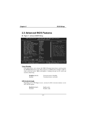
... Warning This option allows you may be able to protect the IDE Hard Disk boot sector. Disabled (default) Enabled Virus protection is used to increase memory access time with this option. CPU L1 & L2 Cache Depending on the screen and sound an alarm beep. Enabled (default) Disabled Enable cache. Disable cache...
... Warning This option allows you may be able to protect the IDE Hard Disk boot sector. Disabled (default) Enabled Virus protection is used to increase memory access time with this option. CPU L1 & L2 Cache Depending on the screen and sound an alarm beep. Enabled (default) Disabled Enable cache. Disable cache...

M7SXD user's manual
Page 49
The Choices: Non-OS2 (default), OS2. Enabled (default) Optional ROM is only used for OS2 systems with memory exceeding 64MB. The Choices: Disabled (default), Enabled. 2-12 The Choices: Disabled (default), Enabled. Video BIOS Shadow Determines whether video BIOS will be copied to RAM ...
The Choices: Non-OS2 (default), OS2. Enabled (default) Optional ROM is only used for OS2 systems with memory exceeding 64MB. The Choices: Disabled (default), Enabled. 2-12 The Choices: Disabled (default), Enabled. Video BIOS Shadow Determines whether video BIOS will be copied to RAM ...

M7SXD user's manual
Page 50
... changed unless you are suspicious that the settings have been changed incorrectly. Figure 4. Chapter 2 BIOS Setup 2.4 Advanced Chipset Features This submenu allows you to system memory resources, such as DRAM and external cache. Advanced Chipset Setup Advanced DRAM Control To control the DDR SDRAM. It also coordinates communications with the following...
... changed unless you are suspicious that the settings have been changed incorrectly. Figure 4. Chapter 2 BIOS Setup 2.4 Advanced Chipset Features This submenu allows you to system memory resources, such as DRAM and external cache. Advanced Chipset Setup Advanced DRAM Control To control the DDR SDRAM. It also coordinates communications with the following...

M7SXD user's manual
Page 51
... Host cycles that hit the aperture range are installing for more information. AGP Aperture Size Select the size of the PCI memory address range dedicated for graphics memory address space. DRAM Addr/Cmd Rate This item allows you can reserve an area of CAS latency depends on the DRAM ... BIOS Setup CAS Latency Setting When synchronous DRAM is installed, the number of clock cycles of system memory for ISA adapter ROM. The Choices: 4M, 8M,16M, 32M, 64M (default), 128M, 256M. Memory Hole at 15M-16M When enabled, you select DRAM Addr/Cmd Rate The Choices: Auto Mode(default),...
... Host cycles that hit the aperture range are installing for more information. AGP Aperture Size Select the size of the PCI memory address range dedicated for graphics memory address space. DRAM Addr/Cmd Rate This item allows you can reserve an area of CAS latency depends on the DRAM ... BIOS Setup CAS Latency Setting When synchronous DRAM is installed, the number of clock cycles of system memory for ISA adapter ROM. The Choices: 4M, 8M,16M, 32M, 64M (default), 128M, 256M. Memory Hole at 15M-16M When enabled, you select DRAM Addr/Cmd Rate The Choices: Auto Mode(default),...

M7SXD user's manual
Page 53
... your system software both support Ultra DMA/100, select Auto to control the onboard S/W modem. IDE Burst Mode This item allows you select System Share Memory Size The Choices: 32 MB (default), 4MB, 8MB, 16MB, 64MB. Onboard SuperIO Device If you highlight the literal "Press Enter" next to the "Onboard Super...
... your system software both support Ultra DMA/100, select Auto to control the onboard S/W modem. IDE Burst Mode This item allows you select System Share Memory Size The Choices: 32 MB (default), 4MB, 8MB, 16MB, 64MB. Onboard SuperIO Device If you highlight the literal "Press Enter" next to the "Onboard Super...

M7SXD user's manual
Page 61
... it . Every peripheral device has a node, which allows I/O devices to the default settings. These locations (4K) are assigned to it is automatically set to the memory locations. Chapter 2 BIOS Setup 2.7 PnP/PCI Configurations This section describes configuring the PCI bus system. The system needs to record and update ESCD to the...
... it . Every peripheral device has a node, which allows I/O devices to the default settings. These locations (4K) are assigned to it is automatically set to the memory locations. Chapter 2 BIOS Setup 2.7 PnP/PCI Configurations This section describes configuring the PCI bus system. The system needs to record and update ESCD to the...
M7SXD user's manual
Page 68
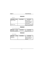
... are lit, hard drive is still dead. Visually inspect the cable; try another cable. circuit Plug in . Visually inspect power cable. PROBABLE CAUSE DIAGNOSIS SOLUTION Memory DIMM is securely plugged in device known to the system at all.
... are lit, hard drive is still dead. Visually inspect the cable; try another cable. circuit Plug in . Visually inspect power cable. PROBABLE CAUSE DIAGNOSIS SOLUTION Memory DIMM is securely plugged in device known to the system at all.
M7SXD user's manual
Page 71
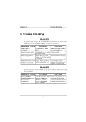
PROBLEM PROBABLE CAUSE Memory problem. Use anti-virus programs to detect and clean viruses. PROBLEM PROBABLE CAUSE Keyboard is enabled. Check keys again, if no improvement replace keyboard. 3-4 DIAGNOSIS SOLUTION Reboot computer. DIAGNOSIS SOLUTION Disable screen saver. Computer virus. Keyboard failure. PROBABLE CAUSE Screen saver is disconnected. DIAGNOSIS SOLUTION Reconnect keyboard. PROBLEM Screen goes blank periodically. Reinstall memory, make sure that all memory modules are installed in correct sockets. Chapter 3 Trouble Shooting No screen.
PROBLEM PROBABLE CAUSE Memory problem. Use anti-virus programs to detect and clean viruses. PROBLEM PROBABLE CAUSE Keyboard is enabled. Check keys again, if no improvement replace keyboard. 3-4 DIAGNOSIS SOLUTION Reboot computer. DIAGNOSIS SOLUTION Disable screen saver. Computer virus. Keyboard failure. PROBABLE CAUSE Screen saver is disconnected. DIAGNOSIS SOLUTION Reconnect keyboard. PROBLEM Screen goes blank periodically. Reinstall memory, make sure that all memory modules are installed in correct sockets. Chapter 3 Trouble Shooting No screen.
M7SXD compatibility test report
Page 2
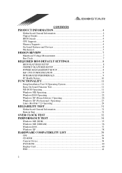
CONTENTS PRODUCT INFORMATION 4 Motherboard General Information 4 Chipset Details ...4 BIOS Details ...4 CPU Supports...4 Memory Supports...4 On-board Features and Devices 4 Mechanical ...5 DESIGN REVIEW 7 Mainboard Voltage Measurement 7 Bus Clock ...7 REQUIRED BIOS DEFAULT SETTINGS 8 BIOS FEATURES SETUP 8 CHIPSET FEATURES SETUP 8 POWER ...
CONTENTS PRODUCT INFORMATION 4 Motherboard General Information 4 Chipset Details ...4 BIOS Details ...4 CPU Supports...4 Memory Supports...4 On-board Features and Devices 4 Mechanical ...5 DESIGN REVIEW 7 Mainboard Voltage Measurement 7 Bus Clock ...7 REQUIRED BIOS DEFAULT SETTINGS 8 BIOS FEATURES SETUP 8 CHIPSET FEATURES SETUP 8 POWER ...
M7SXD compatibility test report
Page 3
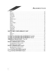
... VCORE OCP & OVP TEST-Ver0.91 60 VCORE OCP & OVP TEST-Ver1.0 60 3 HDD ...41 Joystick...42 Keyboard ...43 LAN Card...43 LAN HUB ...44 Memory ...44 Modem Card...45 Mouse ...45 Monitor...46 Power Supply ...46 Printer ...47 Scanner ...47 SCSI Card...47 Sound Card...48 USB HUB...48 ZIP...
... VCORE OCP & OVP TEST-Ver0.91 60 VCORE OCP & OVP TEST-Ver1.0 60 3 HDD ...41 Joystick...42 Keyboard ...43 LAN Card...43 LAN HUB ...44 Memory ...44 Modem Card...45 Mouse ...45 Monitor...46 Power Supply ...46 Printer ...47 Scanner ...47 SCSI Card...47 Sound Card...48 USB HUB...48 ZIP...


