
M6TSU user's manual
Page 3
Contents Introduction 1-1 1 Motherboard Description 1-2 1.1 Features 1-2 1.1.1 Hardware 1-2 1.1.2 BIOS 1-6 1.1.3 Software 1-6 1.1.4 Accessories 1-6 1.2 Motherboard Installation 1-7 1.2.1 System Block Diagram 1-7 1.2.2 Layout of Motherboard 1-8 1.2.3 Quick Reference 1-9 1.3 CPU Installation 1-10 1.3.1 CPU Installation Procedure: Socket 370 1-10 1.3.2 CPU Fan Header: JCFAN1 1-...
Contents Introduction 1-1 1 Motherboard Description 1-2 1.1 Features 1-2 1.1.1 Hardware 1-2 1.1.2 BIOS 1-6 1.1.3 Software 1-6 1.1.4 Accessories 1-6 1.2 Motherboard Installation 1-7 1.2.1 System Block Diagram 1-7 1.2.2 Layout of Motherboard 1-8 1.2.3 Quick Reference 1-9 1.3 CPU Installation 1-10 1.3.1 CPU Installation Procedure: Socket 370 1-10 1.3.2 CPU Fan Header: JCFAN1 1-...
M6TSU user's manual
Page 4
... Subsystem 1-28 1.7.6.1 AUX Audio in Header: JAUX1 (Optional 1-28 1.7.6.2 Telephony Header: JTAD1 1-29 1.7.6.3 Front AUDIO Header: JAUDIO1 1-29 1.7.6.4 CD Audio-In Headers: JCDIN1/JCDIN2 1-29 2. BIOS Setup 2-1 ii
... Subsystem 1-28 1.7.6.1 AUX Audio in Header: JAUX1 (Optional 1-28 1.7.6.2 Telephony Header: JTAD1 1-29 1.7.6.3 Front AUDIO Header: JAUDIO1 1-29 1.7.6.4 CD Audio-In Headers: JCDIN1/JCDIN2 1-29 2. BIOS Setup 2-1 ii
M6TSU user's manual
Page 5
RAID BIOS Setting (Optional 3-1 3.1 Getting Started 3-1 3.1.1 Introduction 3-1 3.1.2 Main Features & Benefits 3-1 3.2 Installation of Driver 3-2 3.2.1 Introduction 3-2 3.2.2 Windows 98/ME 3-2 3.2.3 Windows NT4.0 3-4 3.2.4 Windows 2000...(RAID 0, for Performance 3-11 3.3.4 Create Mirror Array (RAID 1, for Data Protection 3-16 iii Contents 2.1 Main Menu 2-3 2.2 Standard CMOS Features 2-6 2.3 Advanced BIOS Features 2-9 2.4 Advanced Chipset Features 2-12 2.5 Integrated Peripherals 2-14 2.6 Power Management Setup 2-19 2.7 PnP/PCI Configurations 2-24 2.8 PC Health Status 2-27 2.9 Frequency...
RAID BIOS Setting (Optional 3-1 3.1 Getting Started 3-1 3.1.1 Introduction 3-1 3.1.2 Main Features & Benefits 3-1 3.2 Installation of Driver 3-2 3.2.1 Introduction 3-2 3.2.2 Windows 98/ME 3-2 3.2.3 Windows NT4.0 3-4 3.2.4 Windows 2000...(RAID 0, for Performance 3-11 3.3.4 Create Mirror Array (RAID 1, for Data Protection 3-16 iii Contents 2.1 Main Menu 2-3 2.2 Standard CMOS Features 2-6 2.3 Advanced BIOS Features 2-9 2.4 Advanced Chipset Features 2-12 2.5 Integrated Peripherals 2-14 2.6 Power Management Setup 2-19 2.7 PnP/PCI Configurations 2-24 2.8 PC Health Status 2-27 2.9 Frequency...
M6TSU user's manual
Page 6
... 3-28 3.3.10 Set Transfer Mode 3-29 3.3.11 Device Status 3-30 3.3.12 Hot-swapping Hard Disks of Mirror Array 3-31 3.3.13 Event Log 3-32 3.4 BIOS Configuration 3-33 3.4.1 Enter into BIOS Configuration Utility 3-33 3.4.2 Create RAID 3-34 3.4.3 Delete RAID 3-35 3.4.4 Rebuild Mirror Array 3-35 3.4.5 Add Spare Disk 3-36 3.4.6 Remove Spare Disk 3-36 3.4.7 Set Disk...
... 3-28 3.3.10 Set Transfer Mode 3-29 3.3.11 Device Status 3-30 3.3.12 Hot-swapping Hard Disks of Mirror Array 3-31 3.3.13 Event Log 3-32 3.4 BIOS Configuration 3-33 3.4.1 Enter into BIOS Configuration Utility 3-33 3.4.2 Create RAID 3-34 3.4.3 Delete RAID 3-35 3.4.4 Rebuild Mirror Array 3-35 3.4.5 Add Spare Disk 3-36 3.4.6 Remove Spare Disk 3-36 3.4.7 Set Disk...
M6TSU user's manual
Page 8
... (533MHz and > 566MHz) and Tualatin (FC-PGA2) processor the new generation power for faster performance. Green PC Power Management Functionality − BIOS supported power management. − Power down timer from 533 MHz to 1.2 GHz CPU core speeds. − Supports 33MHz PCI Bus speed. ... − Provides three DIMM module sockets. − Supports 3.3V unbuffered 168pin Synchronous DRAM modules. − Supports a maximum memory size of system BIOS into RAM for high-end workstations and servers. − Provides Socket 370. − Running at 133 MHz system memory bus. − No ...
... (533MHz and > 566MHz) and Tualatin (FC-PGA2) processor the new generation power for faster performance. Green PC Power Management Functionality − BIOS supported power management. − Power down timer from 533 MHz to 1.2 GHz CPU core speeds. − Supports 33MHz PCI Bus speed. ... − Provides three DIMM module sockets. − Supports 3.3V unbuffered 168pin Synchronous DRAM modules. − Supports a maximum memory size of system BIOS into RAM for high-end workstations and servers. − Provides Socket 370. − Running at 133 MHz system memory bus. − No ...
M6TSU user's manual
Page 9
...; High priority access support. − Hierarchical PCI configuration mechanism. − Supports via dual mode buffers to RAM) support. Chapter1 Motherboard Description − Wakes up by BIOS.
...; High priority access support. − Hierarchical PCI configuration mechanism. − Supports via dual mode buffers to RAM) support. Chapter1 Motherboard Description − Wakes up by BIOS.
M6TSU user's manual
Page 11
Chapter1 Motherboard Description − Total ATA bus tri-state by the BIOS. When suggested ratings for temperature, fan speed, or voltage are exceeded, an interrupt is activated. − Fan speed sensors. Dimension (ATX form-factor) − 20cm X ...
Chapter1 Motherboard Description − Total ATA bus tri-state by the BIOS. When suggested ratings for temperature, fan speed, or voltage are exceeded, an interrupt is activated. − Fan speed sensors. Dimension (ATX form-factor) − 20cm X ...
M6TSU user's manual
Page 12
Chapter1 Motherboard Description 1.1.2 BIOS − AWARD BIOS. − ACPI Supported. − Supports APM1.2. − Setting the CPU Host and Memory clock frequency/Ratio. 1.1.3 Software Operating Systems − Offers the highest performance for MS-DOS, Windows NT, Windows 2000, Windows 9x, Windows ME, Windows XP, Novell, LINUX(Red Hat 7.0), UNIX, SCO UNIX etc. 1.1.4 Accessories − HDD Cable. − FDD Cable. − Rear I/O Panel for ATX Case (Optional). − CD for sound, VGA, IDE drivers and modem driver utilities. − Front USB cable (Optional). 1-6
Chapter1 Motherboard Description 1.1.2 BIOS − AWARD BIOS. − ACPI Supported. − Supports APM1.2. − Setting the CPU Host and Memory clock frequency/Ratio. 1.1.3 Software Operating Systems − Offers the highest performance for MS-DOS, Windows NT, Windows 2000, Windows 9x, Windows ME, Windows XP, Novell, LINUX(Red Hat 7.0), UNIX, SCO UNIX etc. 1.1.4 Accessories − HDD Cable. − FDD Cable. − Rear I/O Panel for ATX Case (Optional). − CD for sound, VGA, IDE drivers and modem driver utilities. − Front USB cable (Optional). 1-6
M6TSU user's manual
Page 14
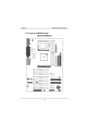
... PCI6 PCI SLOT CNR1 CNR SLOT 1 JSFAN1 HighPonit HPT370A 2 1 24 23 JPANEL1 BAT1 1 JUSB2 1-8 PRIMARY IDE CONN. Chapter1 Motherboard Description 1.2.2 Layout of Motherboard Model No.M6TSU JKBMS1 K/B & Mouse JUSB1 USB JCOM1 JCFAN1 1 JPRNT1 U41 SOCKET 370 COM1 Parallel Port Winbond I/O CPU1 U43 COM2 JCOM2 JSPKR1 SP-OUT JLIN1 LINE-IN JMIC1...
... PCI6 PCI SLOT CNR1 CNR SLOT 1 JSFAN1 HighPonit HPT370A 2 1 24 23 JPANEL1 BAT1 1 JUSB2 1-8 PRIMARY IDE CONN. Chapter1 Motherboard Description 1.2.2 Layout of Motherboard Model No.M6TSU JKBMS1 K/B & Mouse JUSB1 USB JCOM1 JCFAN1 1 JPRNT1 U41 SOCKET 370 COM1 Parallel Port Winbond I/O CPU1 U43 COM2 JCOM2 JSPKR1 SP-OUT JLIN1 LINE-IN JMIC1...
M6TSU user's manual
Page 24
... connector can be attached to a front panel power switch. The LED will power down the monitor and the hard disk when not in the system BIOS and the APM driver must be attached to internal debounce circuitry on the system board). To configure this connector. At least two seconds must pull...
... connector can be attached to a front panel power switch. The LED will power down the monitor and the hard disk when not in the system BIOS and the APM driver must be attached to internal debounce circuitry on the system board). To configure this connector. At least two seconds must pull...
M6TSU user's manual
Page 26
... two HDD connectors IDE1 (primary) and IDE2 (secondary). Assignment 1 5V_SB 2 Ground 3 Wake up to four hard disk drives, a CD-ROM, a 120MB Floppy (reserved for future BIOS) and other devices to IDE1.
... two HDD connectors IDE1 (primary) and IDE2 (secondary). Assignment 1 5V_SB 2 Ground 3 Wake up to four hard disk drives, a CD-ROM, a 120MB Floppy (reserved for future BIOS) and other devices to IDE1.
M6TSU user's manual
Page 36
... processors input/output system. Sleep and Suspend power management modes are implemented via the System Management Interrupt (SMI). The Award BIOS™ installed in battery-backed RAM so that it retains the Setup information when the power is then stored in your system... using Setup. Power management features are supported. APM Support These AWARD BIOS supports Version 1.1&1.2 of the EPA Green PC specification. EPA Green PC Support This AWARD BIOS supports Version 1.03 of the Advanced Power Management (APM) specification. The rest of configuring...
... processors input/output system. Sleep and Suspend power management modes are implemented via the System Management Interrupt (SMI). The Award BIOS™ installed in battery-backed RAM so that it retains the Setup information when the power is then stored in your system... using Setup. Power management features are supported. APM Support These AWARD BIOS supports Version 1.1&1.2 of the EPA Green PC specification. EPA Green PC Support This AWARD BIOS supports Version 1.03 of the Advanced Power Management (APM) specification. The rest of configuring...
M6TSU user's manual
Page 37
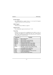
...changes Main Menu - Exit Current page and return to navigate in the Setup program by using the keyboard. Chapter 2 BIOS Setup PCI Bus Support This AWARD BIOS also supports Version 2.1 of the Intel PCI (Peripheral Component Interconnect) local bus specification. DRAM Support SDRAM (Synchronous DRAM...) are supported. CPU. Supported CPUs This AWARD BIOS supports the Intel Pentium® !!! Using Setup In general, you use the arrow keys to highlight items, press to select, use...
...changes Main Menu - Exit Current page and return to navigate in the Setup program by using the keyboard. Chapter 2 BIOS Setup PCI Bus Support This AWARD BIOS also supports Version 2.1 of the Intel PCI (Peripheral Component Interconnect) local bus specification. DRAM Support SDRAM (Synchronous DRAM...) are supported. CPU. Supported CPUs This AWARD BIOS supports the Intel Pentium® !!! Using Setup In general, you use the arrow keys to highlight items, press to select, use...
M6TSU user's manual
Page 38
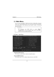
...will appear on board, for reference, please refer to the BIOS installed on the screen. Use the arrow keys to select among the items and press to configure enhanced features of the BIOS. 2-3 Advanced BIOS Features This submenu allows you to select from several setup functions.... The information about BIOS defaults on manual (Figure 1,2,3,4,5,6,7,8,9) is just for update information. Main Menu Standard CMOS...
...will appear on board, for reference, please refer to the BIOS installed on the screen. Use the arrow keys to select among the items and press to configure enhanced features of the BIOS. 2-3 Advanced BIOS Features This submenu allows you to select from several setup functions.... The information about BIOS defaults on manual (Figure 1,2,3,4,5,6,7,8,9) is just for update information. Main Menu Standard CMOS...

M6TSU user's manual
Page 39
...features. Not properly change CPU Vcore Voltage and CPU/PCI clock. (However, this system. Chapter 2 BIOS Setup Advanced Chipset Features This submenu allows you to reload the BIOS when the system is strongly recommended not to use. Frequency/Voltage Control This submenu allows you to configure... Use this menu to operate. PC Health Status This submenu allows you to monitor the hardware of your system to load the BIOS default values for the minimal/stable performance for this function is having problems particularly with the boot sequence. A confirmation message will ...
...features. Not properly change CPU Vcore Voltage and CPU/PCI clock. (However, this system. Chapter 2 BIOS Setup Advanced Chipset Features This submenu allows you to reload the BIOS when the system is strongly recommended not to use. Frequency/Voltage Control This submenu allows you to configure... Use this menu to operate. PC Health Status This submenu allows you to monitor the hardware of your system to load the BIOS default values for the minimal/stable performance for this function is having problems particularly with the boot sequence. A confirmation message will ...
M6TSU user's manual
Page 40
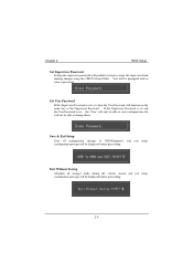
... is set , then the User Password will be displayed before proceeding. Exit Without Saving Abandon all configuration changes to CMOS(memory) and exit setup. Chapter 2 BIOS Setup Set Supervisor Password Setting the supervisor password will not be prompted with to enter a password. confirmation message will function in the same way as...
... is set , then the User Password will be displayed before proceeding. Exit Without Saving Abandon all configuration changes to CMOS(memory) and exit setup. Chapter 2 BIOS Setup Set Supervisor Password Setting the supervisor password will not be prompted with to enter a password. confirmation message will function in the same way as...
M6TSU user's manual
Page 41
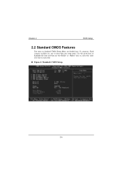
Chapter 2 BIOS Setup 2.2 Standard CMOS Features The items in each item. Each category includes no, one or more than one setup items. Use the arrow keys to highlight the item and then use the or keys to select the value you want in Standard CMOS Setup Menu are divided into 10 categories. Standard CMOS Setup 2-6 Figure 2.
Chapter 2 BIOS Setup 2.2 Standard CMOS Features The items in each item. Each category includes no, one or more than one setup items. Use the arrow keys to highlight the item and then use the or keys to select the value you want in Standard CMOS Setup Menu are divided into 10 categories. Standard CMOS Setup 2-6 Figure 2.
M6TSU user's manual
Page 42
.... 1.44M, 3.5 in 2.88M, 3.5 in its sub Press to enter the menu. IDE Secondary Slave Options are in its sub Press to enter the menu. Chapter 2 BIOS Setup Main Menu Selections This table shows the selections that the 'Day' automatically changes when you can make on the Main Menu. Note that you...
.... 1.44M, 3.5 in 2.88M, 3.5 in its sub Press to enter the menu. IDE Secondary Slave Options are in its sub Press to enter the menu. Chapter 2 BIOS Setup Main Menu Selections This table shows the selections that the 'Day' automatically changes when you can make on the Main Menu. Note that you...
M6TSU user's manual
Page 43
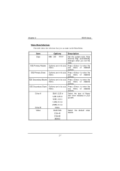
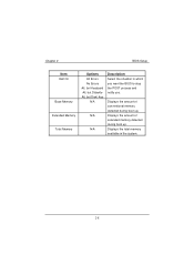
Displays the total memory available in which you want the BIOS to stop the POST process and notify you. Chapter 2 BIOS Setup Item Halt On Base Memory Extended Memory Total Memory Options All Errors No Errors All, but Keyboard All, but Diskette All, but Disk/ Key N/A N/A N/A Description Select the situation in the system. 2-8 Displays the amount of extended memory detected during boot up . Displays the amount of conventional memory detected during boot up .
Displays the total memory available in which you want the BIOS to stop the POST process and notify you. Chapter 2 BIOS Setup Item Halt On Base Memory Extended Memory Total Memory Options All Errors No Errors All, but Keyboard All, but Diskette All, but Disk/ Key N/A N/A N/A Description Select the situation in the system. 2-8 Displays the amount of extended memory detected during boot up . Displays the amount of conventional memory detected during boot up .
M6TSU user's manual
Page 44
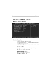
... (default), Yes. 2-9 Report No FDD For WIN 95 Whether report no FDD for Win 95 or not. Advanced BIOS Setup BIOS Setup Boot Seq & Floppy Setup First /Second/Third/ Boot Other Device These BIOS attempts to swap logical drive assignments. The Choices: Enabled, Disabled (default). Swap Floppy Drive For systems with two floppy... the devices in the sequence selected in these items. The Choices: Floppy, LS120, HDD-0, SCSI, CDROM, HDD-1, HDD-2, HDD-3, ZIP100, LAN, HPT370, Disabled. Chapter 2 2.3 Advanced BIOS Features Figure 3.
... (default), Yes. 2-9 Report No FDD For WIN 95 Whether report no FDD for Win 95 or not. Advanced BIOS Setup BIOS Setup Boot Seq & Floppy Setup First /Second/Third/ Boot Other Device These BIOS attempts to swap logical drive assignments. The Choices: Enabled, Disabled (default). Swap Floppy Drive For systems with two floppy... the devices in the sequence selected in these items. The Choices: Floppy, LS120, HDD-0, SCSI, CDROM, HDD-1, HDD-2, HDD-3, ZIP100, LAN, HPT370, Disabled. Chapter 2 2.3 Advanced BIOS Features Figure 3.

