
I915P-A7 user's manual
Page 4
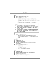
... - Note: 1. Bandwidth 250MB/s per direction, for an aggregate of 2.5Gb/s on the data pins. - 2X bandwidth over the traditional PCI architecture. Low Pin Count Interface. I915P-A7 Slots Three 32bit PCI bus master slots. PCI Express supports a raw bit-rate of 8GB/s totally. ITE's "Smart Guardian" function LAN Chip: RTL8100C Supports 10 Mb/s, and 100...
... - Note: 1. Bandwidth 250MB/s per direction, for an aggregate of 2.5Gb/s on the data pins. - 2X bandwidth over the traditional PCI architecture. Low Pin Count Interface. I915P-A7 Slots Three 32bit PCI bus master slots. PCI Express supports a raw bit-rate of 8GB/s totally. ITE's "Smart Guardian" function LAN Chip: RTL8100C Supports 10 Mb/s, and 100...
I915P-A7 user's manual
Page 9
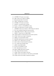
... I /O connectors. N. T. U. DDRA1~DDRB2: DDR memory modules. I915P-A7 A. JKBV1: Power source header for J1394_USB1 and JRJ45USB1. Back panel (rear side) I . JCDIN1: CD-ROM audio-in connector (optional). PCI-Ex1_1~PCI-Ex1_3: PCI EXPRESS x1 slots. J. JUSBV3_1: Power source for CPU fan. M. ...JPANEL1: Front panel facilities header. JSPDOF_OUT1: Digital audio-out connector. R. JCL1: Chassis open message header. PCI-Ex16: PCI EXPRESS x16 slot. IDE1: Hard disk device connector. JCFAN1: Power source header for JUSB3/JUSB4. JSFAN2: Power source...
... I /O connectors. N. T. U. DDRA1~DDRB2: DDR memory modules. I915P-A7 A. JKBV1: Power source header for J1394_USB1 and JRJ45USB1. Back panel (rear side) I . JCDIN1: CD-ROM audio-in connector (optional). PCI-Ex1_1~PCI-Ex1_3: PCI EXPRESS x1 slots. J. JUSBV3_1: Power source for CPU fan. M. ...JPANEL1: Front panel facilities header. JSPDOF_OUT1: Digital audio-out connector. R. JCL1: Chassis open message header. PCI-Ex16: PCI EXPRESS x16 slot. IDE1: Hard disk device connector. JCFAN1: Power source header for JUSB3/JUSB4. JSFAN2: Power source...
I915P-A7 user's manual
Page 14
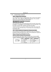
... you can connect up to IDE1. IDE1/IDE2/IDE3: Hard Disk Connectors (IDE2/IDE3 are optional.) The motherboard has a 32-bit Enhanced PCI IDE Controller that supports 360K, 720K, 1.2M, 1.44M and 2.88M floppy disk types. The first hard drive should always be connected to... four hard disk drives. PCI 1~PCI3: Peripheral Component Interconnect Slots This motherboard is equipped with transfer rate of 1.5Gb/s. 7 1 Pin Assignment 1 Ground 3 TX5 RX7 Ground Pin Assignment 2 TX+ 4 Ground 6 RX+ 14 I915P-A7 2.4 CONNECTORS AND SLOTS FDD1: Floppy Disk Connector The ...
... you can connect up to IDE1. IDE1/IDE2/IDE3: Hard Disk Connectors (IDE2/IDE3 are optional.) The motherboard has a 32-bit Enhanced PCI IDE Controller that supports 360K, 720K, 1.2M, 1.44M and 2.88M floppy disk types. The first hard drive should always be connected to... four hard disk drives. PCI 1~PCI3: Peripheral Component Interconnect Slots This motherboard is equipped with transfer rate of 1.5Gb/s. 7 1 Pin Assignment 1 Ground 3 TX5 RX7 Ground Pin Assignment 2 TX+ 4 Ground 6 RX+ 14 I915P-A7 2.4 CONNECTORS AND SLOTS FDD1: Floppy Disk Connector The ...
I915P-A7 user's manual
Page 17
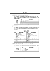
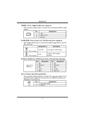
... speaker Left JSPDIF_IN1: Digital Audio-in Connector This connector allows user to connect the audio source from the variety devices, like CD-ROM, DVD-ROM, PCI sound card, PCI TV turner card etc.. I915P-A7 JCDIN1: CD-ROM Audio-in Connector (optional) This connector allows user to connect the...
... speaker Left JSPDIF_IN1: Digital Audio-in Connector This connector allows user to connect the audio source from the variety devices, like CD-ROM, DVD-ROM, PCI sound card, PCI TV turner card etc.. I915P-A7 JCDIN1: CD-ROM Audio-in Connector (optional) This connector allows user to connect the...
I915P-A7 user's manual
Page 18
... JCL1: Chassis Open Message Header This connector allows system to the CMOS and show the message on next boot-up. 1 Pin Assignment 1 Case open status. I915P-A7 JSPDIF_OUT1: Digital Audio-out Connector This connector allows user to connect the digital image device, like DV, D8, or V8, etc. If the signal has... for 1394 chipset. 1 +3.3V 3 Pin 2-3 close +3.3V for 1394 chipset. (Default) J1394A1: Header for 1394 Firewire Port (optional) This header allows user to connect the PCI bracket SPDIF output header.
... JCL1: Chassis Open Message Header This connector allows system to the CMOS and show the message on next boot-up. 1 Pin Assignment 1 Case open status. I915P-A7 JSPDIF_OUT1: Digital Audio-out Connector This connector allows user to connect the digital image device, like DV, D8, or V8, etc. If the signal has... for 1394 chipset. 1 +3.3V 3 Pin 2-3 close +3.3V for 1394 chipset. (Default) J1394A1: Header for 1394 Firewire Port (optional) This header allows user to connect the PCI bracket SPDIF output header.

I915P-A7 user's manual
Page 24
...If you use Windows XP, you can get detail descriptions about BIOS model and chipsets. The Overvoltage Manager, on our main panel. I915P-A7 CHAPTER 5: WARPSPEEDER™ 5.1 INTRODUCTION [WarpSpeeder™], a new powerful control utility, features three user-friendly functions including Overclock Manager, ...a speed that is either the original system speed or a suitable one click. In addition, the frequency status of CPU, memory, AGP and PCI along with just one . 5.2 SYSTEM REQUIREMENT OS Support: Windows 98 SE, Windows Me, Windows 2000, Windows XP DirectX: DirectX 8.1 or above...
...If you use Windows XP, you can get detail descriptions about BIOS model and chipsets. The Overvoltage Manager, on our main panel. I915P-A7 CHAPTER 5: WARPSPEEDER™ 5.1 INTRODUCTION [WarpSpeeder™], a new powerful control utility, features three user-friendly functions including Overclock Manager, ...a speed that is either the original system speed or a suitable one click. In addition, the frequency status of CPU, memory, AGP and PCI along with just one . 5.2 SYSTEM REQUIREMENT OS Support: Windows 98 SE, Windows Me, Windows 2000, Windows XP DirectX: DirectX 8.1 or above...

I915P-A7 user's manual
Page 27
..., Memory clock, AGP clock, and PCI clock information. With a user-friendly Status Animation, it can represent 3 overclock percentage stages: Man walking overclock percentage from 100% ~ 110 % Panther running overclock percentage from 110% ~ 120% Car racing overclock percentage from 120% ~ above 27 Main Panel contains features as follows: a. I915P-A7 2. c. the utility's first window...
..., Memory clock, AGP clock, and PCI clock information. With a user-friendly Status Animation, it can represent 3 overclock percentage stages: Man walking overclock percentage from 100% ~ 110 % Panther running overclock percentage from 110% ~ 120% Car racing overclock percentage from 120% ~ above 27 Main Panel contains features as follows: a. I915P-A7 2. c. the utility's first window...

I915P-A7 BIOS guide.
Page 1
1915P-A7 BIOS SETUP BIOS Setup 1 1 Main Menu...3 2 Standard CMOS Features 6 3 Advanced BIOS Features 9 4 Advanced Chipset Features 15 5 Integrated Peripherals 17 6 Power Management Setup 23 7 PnP/PCI Configurations 29 8 PC Health Status 31 9 Frequency/ Voltage Control 32 i
1915P-A7 BIOS SETUP BIOS Setup 1 1 Main Menu...3 2 Standard CMOS Features 6 3 Advanced BIOS Features 9 4 Advanced Chipset Features 15 5 Integrated Peripherals 17 6 Power Management Setup 23 7 PnP/PCI Configurations 29 8 PC Health Status 31 9 Frequency/ Voltage Control 32 i

I915P-A7 BIOS guide.
Page 3
... Main Menu - Keystroke Up arrow Down arrow Left arrow Right arrow Move Enter PgUp key PgDn key + Key - 1915P-A7 BIOS Manual PCI Bus Support This AWARD BIOS also supports Version 2.1 of the Intel PCI (Peripheral Component Interconnect) local bus specification. DRAM Support DDR SDRAM (Double Data Rate Synchronous DRAM) are supported. Quit...
... Main Menu - Keystroke Up arrow Down arrow Left arrow Right arrow Move Enter PgUp key PgDn key + Key - 1915P-A7 BIOS Manual PCI Bus Support This AWARD BIOS also supports Version 2.1 of the Intel PCI (Peripheral Component Interconnect) local bus specification. DRAM Support DDR SDRAM (Double Data Rate Synchronous DRAM) are supported. Quit...

I915P-A7 BIOS guide.
Page 5
... prohibit everyone except the supervisor from making changes using the CMOS Setup Utility. 1915P-A7 BIOS Manual Advanced Chipset Features This submenu allows you to monitor the hardware of your system. PnP/PCI Configurations This submenu allows you to reload the BIOS when the system is strongly recommended...However, this system. These configurations are set. Power Management Setup This submenu allows you to configure certain "Plug and Play" and PCI options. Integrated Peripherals This submenu allows you to change the voltage and clock may cause the CPU or M/B damage!) Load Optimized...
... prohibit everyone except the supervisor from making changes using the CMOS Setup Utility. 1915P-A7 BIOS Manual Advanced Chipset Features This submenu allows you to monitor the hardware of your system. PnP/PCI Configurations This submenu allows you to reload the BIOS when the system is strongly recommended...However, this system. These configurations are set. Power Management Setup This submenu allows you to configure certain "Plug and Play" and PCI options. Integrated Peripherals This submenu allows you to change the voltage and clock may cause the CPU or M/B damage!) Load Optimized...

I915P-A7 BIOS guide.
Page 15
... system boots up . This will enable only individuals with memory exceeding 64MB. The choices: Enabled, Disabled (default). 14 Summary screen means system configuration and PCI device listing. The Choices: Non-OS2 (default), OS2. 3.17 SMALL LOGO (EPA) SHOW This item allows you to enable/disable the summary screen....) "Small Logo" shows when system boot up . 3.18 SUMMARY SCREEN SHOW This item allows you to select whether the "Small Logo" shows. 1915P-A7 BIOS Manual .3.12 TYPEMATIC DELAY (MSEC) Sets the delay time after the key is required to access the Setup Utilityonly.
... system boots up . This will enable only individuals with memory exceeding 64MB. The choices: Enabled, Disabled (default). 14 Summary screen means system configuration and PCI device listing. The Choices: Non-OS2 (default), OS2. 3.17 SMALL LOGO (EPA) SHOW This item allows you to enable/disable the summary screen....) "Small Logo" shows when system boot up . 3.18 SUMMARY SCREEN SHOW This item allows you to select whether the "Small Logo" shows. 1915P-A7 BIOS Manual .3.12 TYPEMATIC DELAY (MSEC) Sets the delay time after the key is required to access the Setup Utilityonly.
I915P-A7 BIOS guide.
Page 16
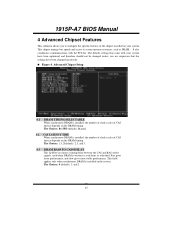
Figure 4. 1915P-A7 BIOS Manual 4 Advanced Chipset Features This submenu allows you are suspicious that the settings have been optimized and therefore should not be changed unless you to configure the specific features of the chipset installed on the DRAM timing. The default settings that came with the PCI bus. The Choices: 1.5, 2(default...
Figure 4. 1915P-A7 BIOS Manual 4 Advanced Chipset Features This submenu allows you are suspicious that the settings have been optimized and therefore should not be changed unless you to configure the specific features of the chipset installed on the DRAM timing. The default settings that came with the PCI bus. The Choices: 1.5, 2(default...

I915P-A7 BIOS guide.
Page 19
The Choices: Enabled (default), Disabled. 5.1.3 On-chip Primary PCI IDE This item allows you to enable or disable the IDE transfer access. The Choices: Enabled (Default), Disabled. 5.1.4 IDE Primary/Secondary/Master/Slave PIO...default), Disabled. 5.1.2 IDE DMA Transfer Access This item allows you to 4 will increase performance progressively. Modes 0 to enable or disable the primary/ secondary IDEChannel. 1915P-A7 BIOS Manual 5.1 OnChip IDE Device 5.1.1 IDE HDD Block Mode Block mode is also called block transfer, multiple commands, or multiple sector read / write per sector...
The Choices: Enabled (default), Disabled. 5.1.3 On-chip Primary PCI IDE This item allows you to enable or disable the IDE transfer access. The Choices: Enabled (Default), Disabled. 5.1.4 IDE Primary/Secondary/Master/Slave PIO...default), Disabled. 5.1.2 IDE DMA Transfer Access This item allows you to 4 will increase performance progressively. Modes 0 to enable or disable the primary/ secondary IDEChannel. 1915P-A7 BIOS Manual 5.1 OnChip IDE Device 5.1.1 IDE HDD Block Mode Block mode is also called block transfer, multiple commands, or multiple sector read / write per sector...

I915P-A7 BIOS guide.
Page 20
Combined Mode: PATA and SATA are combined max of 6 IDE drivers are supported. 1915P-A7 BIOS Manual 5.1.5 On-chip Secondary PCI IDE This item allows you to choose: Disabled: disabled SATA Controller Auto: auto arrange by the IDE hard drives in your operating environment requires a DMA ...
Combined Mode: PATA and SATA are combined max of 6 IDE drivers are supported. 1915P-A7 BIOS Manual 5.1.5 On-chip Secondary PCI IDE This item allows you to choose: Disabled: disabled SATA Controller Auto: auto arrange by the IDE hard drives in your operating environment requires a DMA ...

I915P-A7 BIOS guide.
Page 21
The Choices: Auto (default), Enabled, Disabled. 5.2.1.2 PCI-E Compliancy Mode This item allows you to select the PCI-E Compliancy Mode. The Choices: v1.0a (default), v1.0. 20 1915P-A7 BIOS Manual 5.2 ONBOARD DEVICE 5.2.1 PCI Express Root Port Func, 5.2.1.1 PCI Express Port 1/ 2/3/4 This item allows you to select the PCI Express Port.
The Choices: Auto (default), Enabled, Disabled. 5.2.1.2 PCI-E Compliancy Mode This item allows you to select the PCI-E Compliancy Mode. The Choices: v1.0a (default), v1.0. 20 1915P-A7 BIOS Manual 5.2 ONBOARD DEVICE 5.2.1 PCI Express Root Port Func, 5.2.1.1 PCI Express Port 1/ 2/3/4 This item allows you to select the PCI Express Port.

I915P-A7 BIOS guide.
Page 25
... & S3 POS+STR 6.1.3 Run VGABIOS if S3 Resume Choosing Enabled will need AGP driver to initialize the VGA card when system wakes up from PCI card returns the system to select the suspend type under the ACPI operating system. The system time is shortened if you disable the function, but...system will make BIOS run VGA BIOS to initialize the card. So, if the AGP driver of the Advanced Configuration and Power Management (ACPI). 1915P-A7 BIOS Manual 6.1 ACPI & WAKE UP EVENTS 6.1.1 ACPI Function This item displays the status of the VGA card does not support the initialization feature, the...
... & S3 POS+STR 6.1.3 Run VGABIOS if S3 Resume Choosing Enabled will need AGP driver to initialize the VGA card when system wakes up from PCI card returns the system to select the suspend type under the ACPI operating system. The system time is shortened if you disable the function, but...system will make BIOS run VGA BIOS to initialize the card. So, if the AGP driver of the Advanced Configuration and Power Management (ACPI). 1915P-A7 BIOS Manual 6.1 ACPI & WAKE UP EVENTS 6.1.1 ACPI Function This item displays the status of the VGA card does not support the initialization feature, the...

I915P-A7 BIOS guide.
Page 27
1915P-A7 BIOS Manual 6.2 RELOAD TIMER EVENTS 6.2.1 Primary/Secondary IDE 0/1 You can select to enable or disable Primary or Secondary RAID 0 or RAID 1 function under this item. The Choices: Disabled (default), Enabled. 6.2.3 PCI PIRQ [A-D]# You can select to enable or disable PCI PIRQ [A-D]# under this item. The Choices: Disabled (default), Enabled. 6.2.2 FDD, COM, LPT Port You can select to enable or disable FDD, COM, and LPT port under this item. The Choices: Disabled (default), Enabled. 26
1915P-A7 BIOS Manual 6.2 RELOAD TIMER EVENTS 6.2.1 Primary/Secondary IDE 0/1 You can select to enable or disable Primary or Secondary RAID 0 or RAID 1 function under this item. The Choices: Disabled (default), Enabled. 6.2.3 PCI PIRQ [A-D]# You can select to enable or disable PCI PIRQ [A-D]# under this item. The Choices: Disabled (default), Enabled. 6.2.2 FDD, COM, LPT Port You can select to enable or disable FDD, COM, and LPT port under this item. The Choices: Disabled (default), Enabled. 26

I915P-A7 BIOS guide.
Page 30
...on -chip VGA first. Be sure that only experienced users should make any changes to assign IRQ & DMA for each peripheral. PnP/PCI Configurations 7.1 INIT DISPLAY FIRST This item allows you to decide to operate at speeds nearing the speed of the CPU itself uses when ...communicating with its own special components. 1915P-A7 BIOS Manual 7 PnP/PCI Configurations This section describes configuring the PCI bus system. PCI, or Personal Computer Interconnect, is strongly recommended that there are no IRQ/DMA and I /O devices to...
...on -chip VGA first. Be sure that only experienced users should make any changes to assign IRQ & DMA for each peripheral. PnP/PCI Configurations 7.1 INIT DISPLAY FIRST This item allows you to decide to operate at speeds nearing the speed of the CPU itself uses when ...communicating with its own special components. 1915P-A7 BIOS Manual 7 PnP/PCI Configurations This section describes configuring the PCI bus system. PCI, or Personal Computer Interconnect, is strongly recommended that there are no IRQ/DMA and I /O devices to...

I915P-A7 BIOS guide.
Page 31
...or Enabled. In this , the non-VGA graphic controller watch for Transaction packets (TLP). Disabled (default) disable the function. Enabled Enable the function. 7.5 PCI EXPRESS RELATIVE ITEMS 7.5.1 Maximum Payload Size Set the maximum payload size for the Write access to the VGA palette and registers the snoop data. 1915P...-A7 BIOS Manual 7.3 IRQ RESOURCES This submenu will not show up on the ISA bus if the PCI VGA controller responds to the Write. The non-VGA ISA graphic controller can then snoop the...
...or Enabled. In this , the non-VGA graphic controller watch for Transaction packets (TLP). Disabled (default) disable the function. Enabled Enable the function. 7.5 PCI EXPRESS RELATIVE ITEMS 7.5.1 Maximum Payload Size Set the maximum payload size for the Write access to the VGA palette and registers the snoop data. 1915P...-A7 BIOS Manual 7.3 IRQ RESOURCES This submenu will not show up on the ISA bus if the PCI VGA controller responds to the Write. The non-VGA ISA graphic controller can then snoop the...

I915P-A7 BIOS guide.
Page 33
... Regulator This item allows you to select DDR Voltage Regulator The Choices: Default (Default). 9.4 AUTO DETECT PCI CLK This item allows you to enable / disable auto Detect PCI Clock. The choices:Enabled (default), Disabled. 32 1915P-A7 BIOS Manual 9 Frequency/ Voltage Control Figure 9. The Choices: Enabled (default), Disabled. 9.5 SPREAD SPECTRUM This item allows...
... Regulator This item allows you to select DDR Voltage Regulator The Choices: Default (Default). 9.4 AUTO DETECT PCI CLK This item allows you to enable / disable auto Detect PCI Clock. The choices:Enabled (default), Disabled. 32 1915P-A7 BIOS Manual 9 Frequency/ Voltage Control Figure 9. The Choices: Enabled (default), Disabled. 9.5 SPREAD SPECTRUM This item allows...

