Update Manual
Page 3
... Updating BIOS with FAT32/16 format and single partition. 2. Press the [Y] key to restart the computer. BIOSTAR BIOS flasher BIOSTAR BIOS Flasher is a BIOS flashing utility providing you an easy and simple way to update your reference only....into a USB flash (pen) drive. 3. All the information and content above are subject to restart the system. The BIOSTAR BIOS Flasher is completed. To enter the utility, press during the POST process. 5. Click Yes to the USB port...while updating the BIOS will lead to search for the motherboard. 2. Choose [fs0] to system boot failure.
... Updating BIOS with FAT32/16 format and single partition. 2. Press the [Y] key to restart the computer. BIOSTAR BIOS flasher BIOSTAR BIOS Flasher is a BIOS flashing utility providing you an easy and simple way to update your reference only....into a USB flash (pen) drive. 3. All the information and content above are subject to restart the system. The BIOSTAR BIOS Flasher is completed. To enter the utility, press during the POST process. 5. Click Yes to the USB port...while updating the BIOS will lead to search for the motherboard. 2. Choose [fs0] to system boot failure.
Setup Manual
Page 2
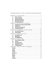
Table of Contents Chapter 1: Introduction 1 1.1 Before You Start 1 1.2 Package Checklist 1 1.3 Motherboard Features 2 1.4 Rear Panel Connectors 4 1.5 Motherboard Layout 5 Chapter 2: Hardware Installation 6 2.1 Installing Central Processing Unit (CPU 6 2.2 FAN Headers 8 2.3 Installing System Memory 9 2.4 Connectors and Slots 11 Chapter 3: Headers & Jumpers Setup 14 3.1 How to ...
Table of Contents Chapter 1: Introduction 1 1.1 Before You Start 1 1.2 Package Checklist 1 1.3 Motherboard Features 2 1.4 Rear Panel Connectors 4 1.5 Motherboard Layout 5 Chapter 2: Hardware Installation 6 2.1 Installing Central Processing Unit (CPU 6 2.2 FAN Headers 8 2.3 Installing System Memory 9 2.4 Connectors and Slots 11 Chapter 3: Headers & Jumpers Setup 14 3.1 How to ...
Setup Manual
Page 3
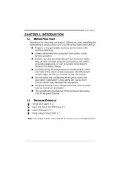
...INTRODUCTION H77MU3 1.1 BEFORE YOU START Thank you take the motherboard out from dangerous area, such as heat source, humid air and water. „ The operating temperatures of the board unless necessary. Loose parts will cause short circuits which may be 0 to area or your motherboard version... 45 degrees Celsius. 1.2 PACKAGE CHECKLIST Serial ATA Cable X 2 Rear I/O Panel for choosing our product. Before you start installing the motherboard, please make sure you follow the instructions below: „ Prepare a dry and stable working environment with sufficient lighting. „ Always...
...INTRODUCTION H77MU3 1.1 BEFORE YOU START Thank you take the motherboard out from dangerous area, such as heat source, humid air and water. „ The operating temperatures of the board unless necessary. Loose parts will cause short circuits which may be 0 to area or your motherboard version... 45 degrees Celsius. 1.2 PACKAGE CHECKLIST Serial ATA Cable X 2 Rear I/O Panel for choosing our product. Before you start installing the motherboard, please make sure you follow the instructions below: „ Prepare a dry and stable working environment with sufficient lighting. „ Always...
Setup Manual
Page 4
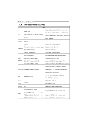
...(x4) x1 Supports PCI-E Gen3 x16 expansion card Supports PCI-E Gen2 x16 expansion card PCI Express Gen2 x 1 slot x2 Supports PCI-E Gen2 x1 expansion cards 2 Motherboard Manual 1.3 MOTHERBOARD FEATURES SPEC Supports Execute Disable Bit / Enhanced Intel Socket 1155 SpeedStep® / Intel Architecture-64 / Extended CPU Intel Core i7 / i5 / i3 / Pentium / Celeron...
...(x4) x1 Supports PCI-E Gen3 x16 expansion card Supports PCI-E Gen2 x16 expansion card PCI Express Gen2 x 1 slot x2 Supports PCI-E Gen2 x1 expansion cards 2 Motherboard Manual 1.3 MOTHERBOARD FEATURES SPEC Supports Execute Disable Bit / Enhanced Intel Socket 1155 SpeedStep® / Intel Architecture-64 / Extended CPU Intel Core i7 / i5 / i3 / Pentium / Celeron...
Setup Manual
Page 6
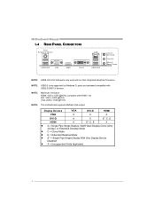
NOTE: Maximum resolution: HDMI: 1920 x 1200 @60Hz, compliant with an Intel integrated Graphics Processor. Motherboard Manual 1.4 REAR PANEL CONNECTORS PS /2 Keyboard / Mouse US B2 .0X 2 VGA HDMI DVI-D LAN USB 3 .0X 2 Line In/ Surround Line Out Mic In 1/... Bass/ Center NOTE: HDMI, DVI-D & VGA ports only work with HDMI 1.4a DVI: 1920 x 1200 @60Hz VGA: 2048 x 1536 @75Hz NOTE: This motherboard supports Multiple VGA output: Display Devices VGA DVI-D HDMI VGA X A A DVI-D HDMI A X S1, C, E A S1, C, E X z A = Single Pipe Single Display, Intel® Dual Display ...
NOTE: Maximum resolution: HDMI: 1920 x 1200 @60Hz, compliant with an Intel integrated Graphics Processor. Motherboard Manual 1.4 REAR PANEL CONNECTORS PS /2 Keyboard / Mouse US B2 .0X 2 VGA HDMI DVI-D LAN USB 3 .0X 2 Line In/ Surround Line Out Mic In 1/... Bass/ Center NOTE: HDMI, DVI-D & VGA ports only work with HDMI 1.4a DVI: 1920 x 1200 @60Hz VGA: 2048 x 1536 @75Hz NOTE: This motherboard supports Multiple VGA output: Display Devices VGA DVI-D HDMI VGA X A A DVI-D HDMI A X S1, C, E A S1, C, E X z A = Single Pipe Single Display, Intel® Dual Display ...
Setup Manual
Page 7
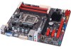
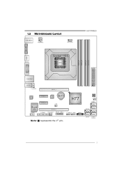
S ATA 6 SATA 3 SATA 4 5 VGA1 1.5 MOTHERBOARD LAYOUT USB_KBMS1 C PU _FA N1 H77MU3 HD MI1 Socket 1155 C PU1 DDR3 _A1 DDR3 _A2 DDR3 _B1 DD R3_B2 ATXPW R1 DVI1 R J45U SB1 A UDI O1 F_ AU DIO1 PE X16_1 CODEC Super I/O J_C OM1 P E X1_1 P E X1_2 LAN BAT1 C IR1 H77 J_ PR IN T1 PE X16_2 SY S_FA N1 JFRONT_USB3_1 F_US B 2 F_US B1 PANE L1 BIOS JC MOS 1 SATA 1 SATA 2 S ATA 5 Note: ■ represents the 1st pin.
S ATA 6 SATA 3 SATA 4 5 VGA1 1.5 MOTHERBOARD LAYOUT USB_KBMS1 C PU _FA N1 H77MU3 HD MI1 Socket 1155 C PU1 DDR3 _A1 DDR3 _A2 DDR3 _B1 DD R3_B2 ATXPW R1 DVI1 R J45U SB1 A UDI O1 F_ AU DIO1 PE X16_1 CODEC Super I/O J_C OM1 P E X1_1 P E X1_2 LAN BAT1 C IR1 H77 J_ PR IN T1 PE X16_2 SY S_FA N1 JFRONT_USB3_1 F_US B 2 F_US B1 PANE L1 BIOS JC MOS 1 SATA 1 SATA 2 S ATA 5 Note: ■ represents the 1st pin.
Setup Manual
Page 8
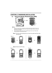
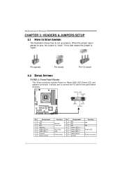
Please refer below instruction to ensure pin legs won't be damaged. 2. When the CPU is removed, cover the Pin Cap on the empty socket to remove the pin cap. Remove Pin Cap before installation, and make good preservation for future use. The motherboard might equip with two different types of pin cap. Step 1: Pull the socket locking lever out from the socket and then raise the lever up. Step 2: Remove the Pin Cap. 6 Motherboard Manual CHAPTER 2: HARDWARE INSTALLATION 2.1 INSTALLING CENTRAL PROCESSING UNIT (CPU) Notice: 1.
Please refer below instruction to ensure pin legs won't be damaged. 2. When the CPU is removed, cover the Pin Cap on the empty socket to remove the pin cap. Remove Pin Cap before installation, and make good preservation for future use. The motherboard might equip with two different types of pin cap. Step 1: Pull the socket locking lever out from the socket and then raise the lever up. Step 2: Remove the Pin Cap. 6 Motherboard Manual CHAPTER 2: HARDWARE INSTALLATION 2.1 INSTALLING CENTRAL PROCESSING UNIT (CPU) Notice: 1.
Setup Manual
Page 10
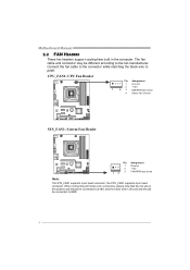
... may be connected to pin#1. the CPU_FAN1 supports 4-pin head connector. Connect the fan cable to the connector while matching the black wire to GND. 8 Motherboard Manual 2.2 FAN HEADERS These fan headers support cooling-fans built in the computer.
... may be connected to pin#1. the CPU_FAN1 supports 4-pin head connector. Connect the fan cable to the connector while matching the black wire to GND. 8 Motherboard Manual 2.2 FAN HEADERS These fan headers support cooling-fans built in the computer.
Setup Manual
Page 12
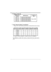
Motherboard Manual B. C. Memory Capacity DIMM Socket Location DDR3 Module DDR3_A1 512MB/1GB/2GB/4GB/8GB DDR3_A2 512MB/1GB/2GB/4GB/8GB DDR3_B1 512MB/1GB/2GB/4GB/...
Motherboard Manual B. C. Memory Capacity DIMM Socket Location DDR3 Module DDR3_A1 512MB/1GB/2GB/4GB/8GB DDR3_A2 512MB/1GB/2GB/4GB/8GB DDR3_B1 512MB/1GB/2GB/4GB/...
Setup Manual
Page 13
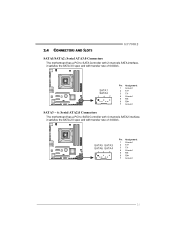
SATA1 SATA2 14 7 Pin Assignment 1 Ground 2 TX+ 3 TX4 Ground 5 RX6 RX+ 7 Ground SATA3 ~ 6: Serial ATA2.0 Connectors The motherboard has a PCI to SATA Controller with 2 channels SATA interface, it satisfies the SATA 2.0 spec and with transfer rate of 3.0Gb/s. 2.4 CONNECTORS AND SLOTS H77MU3 SATA1/SATA2: Serial ATA3.0 Connectors The motherboard has a PCI to SATA Controller with 4 channels SATA2 interface, it satisfies the SATA 3.0 spec and with transfer rate of 6.0Gb/s. SATA5 SATA3 SATA6 SATA4 14 7 Pin Assignment 1 Ground 2 TX+ 3 TX4 Ground 5 RX6 RX+ 7 Ground 11
SATA1 SATA2 14 7 Pin Assignment 1 Ground 2 TX+ 3 TX4 Ground 5 RX6 RX+ 7 Ground SATA3 ~ 6: Serial ATA2.0 Connectors The motherboard has a PCI to SATA Controller with 2 channels SATA interface, it satisfies the SATA 2.0 spec and with transfer rate of 3.0Gb/s. 2.4 CONNECTORS AND SLOTS H77MU3 SATA1/SATA2: Serial ATA3.0 Connectors The motherboard has a PCI to SATA Controller with 4 channels SATA2 interface, it satisfies the SATA 3.0 spec and with transfer rate of 6.0Gb/s. SATA5 SATA3 SATA6 SATA4 14 7 Pin Assignment 1 Ground 2 TX+ 3 TX4 Ground 5 RX6 RX+ 7 Ground 11
Setup Manual
Page 14
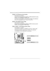
PCI-E 3.0 is supported by Core i7-3xxx / i5-3xxx CPU. PEX1_1/PEX1_2: PCI-Express Gen2 x1 Slot - PCI-Express 3.0 compliant. - Motherboard Manual PEX16_1: PCI-Express Gen3 x16 Slot - PCI-Express 2.0 compliant. - PCI-Express 2.0 compliant. - PCI-Express supports a raw bit-rate of 8.0Gb/s on the data pins. - ...
PCI-E 3.0 is supported by Core i7-3xxx / i5-3xxx CPU. PEX1_1/PEX1_2: PCI-Express Gen2 x1 Slot - PCI-Express 3.0 compliant. - Motherboard Manual PEX16_1: PCI-Express Gen3 x16 Slot - PCI-Express 2.0 compliant. - PCI-Express 2.0 compliant. - PCI-Express supports a raw bit-rate of 8.0Gb/s on the data pins. - ...
Setup Manual
Page 16
... LED (-) Power button Ground Function N/A N/A Power LED Power-on pins, the jumper is "close", if not, that means the jumper is placed on button 14 Motherboard Manual CHAPTER 3: HEADERS & JUMPERS SETUP 3.1 HOW TO SETUP JUMPERS The illustration shows how to connect the PC case's front panel switch functions. Pin opened Pin...
... LED (-) Power button Ground Function N/A N/A Power LED Power-on pins, the jumper is "close", if not, that means the jumper is placed on button 14 Motherboard Manual CHAPTER 3: HEADERS & JUMPERS SETUP 3.1 HOW TO SETUP JUMPERS The illustration shows how to connect the PC case's front panel switch functions. Pin opened Pin...
Setup Manual
Page 18
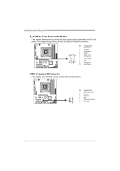
Pin Assignment 1 Mic Left in 2 Ground 3 Mic Right in 4 GPIO 10 9 5 Right line in 6 Jack Sense 7 Front Sense 8 Key 2 1 9 Left line in 10 Jack Sense CIR1: Consumer IR Connector This header is for infrared remote control and communication. 26 15 Pin Assignment 1 IrDA serial input 2 Ground 3 Ground 4 Key 5 IrDA serial output 6 IR Power 16 This header supports HD and AC'97 audio front panel connector. Motherboard Manual F_AUDIO1: Front Panel Audio Header This header allows user to connect the front audio output cable with the PC front panel.
Pin Assignment 1 Mic Left in 2 Ground 3 Mic Right in 4 GPIO 10 9 5 Right line in 6 Jack Sense 7 Front Sense 8 Key 2 1 9 Left line in 10 Jack Sense CIR1: Consumer IR Connector This header is for infrared remote control and communication. 26 15 Pin Assignment 1 IrDA serial input 2 Ground 3 Ground 4 Key 5 IrDA serial output 6 IR Power 16 This header supports HD and AC'97 audio front panel connector. Motherboard Manual F_AUDIO1: Front Panel Audio Header This header allows user to connect the front audio output cable with the PC front panel.
Setup Manual
Page 19
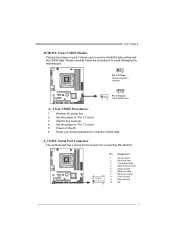
...: Normal Operation (default). 13 13 Pin 2-3 Close: Clear CMOS data. ※ Clear CMOS Procedures: 1. J_COM1: Serial Port Connector The motherboard has a Serial Port Connector for five seconds. 4. Please carefully follow the procedures to "Pin 1-2 close ". 3. Set the jumper to restore...setting and the CMOS data. Reset your desired password or clear the CMOS data. Power on pin2-3 allows user to "Pin 2-3 close ". 5. H77MU3 JCMOS1: Clear CMOS Header Placing the jumper on the AC. 6. Remove AC power line. 2. Pin Assignment 1 Carrier detect 2 Received data 3 Transmitted...
...: Normal Operation (default). 13 13 Pin 2-3 Close: Clear CMOS data. ※ Clear CMOS Procedures: 1. J_COM1: Serial Port Connector The motherboard has a Serial Port Connector for five seconds. 4. Please carefully follow the procedures to "Pin 1-2 close ". 3. Set the jumper to restore...setting and the CMOS data. Reset your desired password or clear the CMOS data. Power on pin2-3 allows user to "Pin 2-3 close ". 5. H77MU3 JCMOS1: Clear CMOS Header Placing the jumper on the AC. 6. Remove AC power line. 2. Pin Assignment 1 Carrier detect 2 Received data 3 Transmitted...
Setup Manual
Page 20
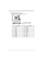
Pin Assignment 1 -Strobe 2 -ALF 3 Data 0 4 -Error 5 Data 1 6 -Init 7 Data 2 8 -Scltin 9 Data 3 10 Ground 11 Data 4 12 Ground 13 Data 5 2 26 1 25 Pin Assignment 14 Ground 15 Data 6 16 Ground 17 Data 7 18 Ground 19 -ACK 20 Ground 21 Busy 22 Ground 23 PE 24 Ground 25 SCLT 26 Key 18 Motherboard Manual J_PRINT1: Printer Port Connector This header allows you to connector printer on the PC.
Pin Assignment 1 -Strobe 2 -ALF 3 Data 0 4 -Error 5 Data 1 6 -Init 7 Data 2 8 -Scltin 9 Data 3 10 Ground 11 Data 4 12 Ground 13 Data 5 2 26 1 25 Pin Assignment 14 Ground 15 Data 6 16 Ground 17 Data 7 18 Ground 19 -ACK 20 Ground 21 Busy 22 Ground 23 PE 24 Ground 25 SCLT 26 Key 18 Motherboard Manual J_PRINT1: Printer Port Connector This header allows you to connector printer on the PC.
Setup Manual
Page 22
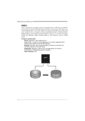
... storage space of one drive fail, the controller switches to the other application that eliminates tedious manual backups to more expensive and less reliable media. Motherboard Manual RAID 1: Every read and write is actually carried out in parallel across 2 disk drives in the array.
... storage space of one drive fail, the controller switches to the other application that eliminates tedious manual backups to more expensive and less reliable media. Motherboard Manual RAID 1: Every read and write is actually carried out in parallel across 2 disk drives in the array.
Setup Manual
Page 24
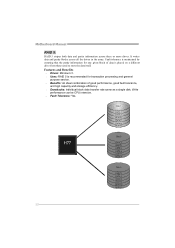
... capacity and storage efficiency. Drawbacks: Individual block data transfer rate same as a single disk. Write performance can be CPU intensive. Fault Tolerance: Yes. Motherboard Manual RAID 5: RAID 5 stripes both data and parity information across all the drives in the array. Disk 1 DATA 1 DATA 3 PARITY DATA 7 DATA 9 PARITY Disk 2 DATA...
... capacity and storage efficiency. Drawbacks: Individual block data transfer rate same as a single disk. Write performance can be CPU intensive. Fault Tolerance: Yes. Motherboard Manual RAID 5: RAID 5 stripes both data and parity information across all the drives in the array. Disk 1 DATA 1 DATA 3 PARITY DATA 7 DATA 9 PARITY Disk 2 DATA...
Setup Manual
Page 25
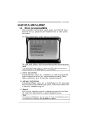
...the following window after you insert the Driver CD, please use file browser to locate and execute the file SETUP.EXE under your motherboard and operating system. The setup guide will need Acrobat Reader to launch the installation program. Note: You will list the software ...available for available manual. CHAPTER 5: USEFUL HELP H77MU3 5.1 DRIVER INSTALLATION NOTE After you installed your operating system, please insert the Fully Setup Driver CD into your optical drive and install the driver for your motherboard and operating system. Note: If this window didn't show up...
...the following window after you insert the Driver CD, please use file browser to locate and execute the file SETUP.EXE under your motherboard and operating system. The setup guide will need Acrobat Reader to launch the installation program. Note: You will list the software ...available for available manual. CHAPTER 5: USEFUL HELP H77MU3 5.1 DRIVER INSTALLATION NOTE After you installed your operating system, please insert the Fully Setup Driver CD into your optical drive and install the driver for your motherboard and operating system. Note: If this window didn't show up...
Setup Manual
Page 26
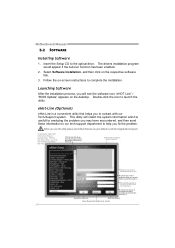
... then send these in the mail . *Describe conditi on of your system. *Select your default e-mail clientapplication program. *represents important informa ti on the desktop. Motherboard Manual 5.2 SOFTWARE Installing Software 1. The drivers installation program would be able to help you . Select Software Installation, and then click on -screen instructions to you...
... then send these in the mail . *Describe conditi on of your system. *Select your default e-mail clientapplication program. *represents important informa ti on the desktop. Motherboard Manual 5.2 SOFTWARE Installing Software 1. The drivers installation program would be able to help you . Select Software Installation, and then click on -screen instructions to you...
Setup Manual
Page 27
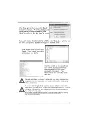
...send the file to our tech support with any other e-mail application. Go to the following web http://www.biostar.com.tw/app/en-us/about/contact.php for your default e-mail client application, you will not share customer's... data with other third parties, so please feel free to provide your system information including motherboard/BIOS/CPU/video/ device/OS information. Open the saved .txt file, you may need to save this information, click... mail out. After filling up this information to a .txt file, click "Save As..." H77MU3 If you to a .txt file.
...send the file to our tech support with any other e-mail application. Go to the following web http://www.biostar.com.tw/app/en-us/about/contact.php for your default e-mail client application, you will not share customer's... data with other third parties, so please feel free to provide your system information including motherboard/BIOS/CPU/video/ device/OS information. Open the saved .txt file, you may need to save this information, click... mail out. After filling up this information to a .txt file, click "Save As..." H77MU3 If you to a .txt file.


