Setup Manual
Page 2
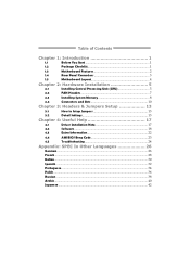
Table of Contents Chapter 1: Introduction 1 1.1 Before You Start 1 1.2 Package Checklist 1 1.3 Motherboard Features 2 1.4 Rear Panel Connectors 3 1.5 Motherboard Layout 4 Chapter 2: Hardware Installation 5 2.1 Installing Central Processing Unit (CPU 5 2.2 FAN Headers 7 2.3 Installing System Memory 8 2.4 Connectors and Slots 10 Chapter 3: Headers & Jumpers Setup 13 3.1 How to ...
Table of Contents Chapter 1: Introduction 1 1.1 Before You Start 1 1.2 Package Checklist 1 1.3 Motherboard Features 2 1.4 Rear Panel Connectors 3 1.5 Motherboard Layout 4 Chapter 2: Hardware Installation 5 2.1 Installing Central Processing Unit (CPU 5 2.2 FAN Headers 7 2.3 Installing System Memory 8 2.4 Connectors and Slots 10 Chapter 3: Headers & Jumpers Setup 13 3.1 How to ...

Setup Manual
Page 3
Loose parts will cause short circuits which may be 0 to area or your motherboard version. 1 TH61MU3/H61MU3/H61MH/H61ML CHAPTER 1: INTRODUCTION 1.1 BEFORE YOU START Thank you take the motherboard out from dangerous area, such as heat source, humid air and water. „ The operating temperatures of the board unless necessary. Before you start installing...
Loose parts will cause short circuits which may be 0 to area or your motherboard version. 1 TH61MU3/H61MU3/H61MH/H61ML CHAPTER 1: INTRODUCTION 1.1 BEFORE YOU START Thank you take the motherboard out from dangerous area, such as heat source, humid air and water. „ The operating temperatures of the board unless necessary. Before you start installing...

Setup Manual
Page 4
Motherboard Manual 1.3 MOTHERBOARD FEATURES TH61MU3 / H61MU3 H61MH / H61ML Socket 1155 Socket 1155 Intel Core i7 / i5 / i3/ Pentium processor Intel Core i7 / i5 / i3/ Pentium processor Supports Execute Disable Bit / Enhanced ...
Motherboard Manual 1.3 MOTHERBOARD FEATURES TH61MU3 / H61MU3 H61MH / H61ML Socket 1155 Socket 1155 Intel Core i7 / i5 / i3/ Pentium processor Intel Core i7 / i5 / i3/ Pentium processor Supports Execute Disable Bit / Enhanced ...

Setup Manual
Page 5
... Port x1 DVI-D Port x1 LAN Port x1 USB2.0 Port x4 Audio Jack x3 200 (W) x 244 (L) mm Windows XP / Vista / 7 Biostar reserves the right to add or remove support for any OS with or without notice 1.4 REAR PANEL CONNECTORS PS /2 Keyboard / Mouse USB2.0X2 HDMI ...3 .0X 2 (For TH61MU3 & H61MU3) USB 2 .0X 2 (For H61MH & H61ML) NOTE: HDMI / DVI-D / VGA Output require an Intel Core family processor with Intel Graphics Technology. NOTE: Maximum resolution: HDMI: 1920 x 1200 @60Hz DVI: 1920 x 1200 @60Hz VGA: 2048 x 1536 @75Hz NOTE: This motherboard supports Multiple VGA output, and the...
... Port x1 DVI-D Port x1 LAN Port x1 USB2.0 Port x4 Audio Jack x3 200 (W) x 244 (L) mm Windows XP / Vista / 7 Biostar reserves the right to add or remove support for any OS with or without notice 1.4 REAR PANEL CONNECTORS PS /2 Keyboard / Mouse USB2.0X2 HDMI ...3 .0X 2 (For TH61MU3 & H61MU3) USB 2 .0X 2 (For H61MH & H61ML) NOTE: HDMI / DVI-D / VGA Output require an Intel Core family processor with Intel Graphics Technology. NOTE: Maximum resolution: HDMI: 1920 x 1200 @60Hz DVI: 1920 x 1200 @60Hz VGA: 2048 x 1536 @75Hz NOTE: This motherboard supports Multiple VGA output, and the...

Setup Manual
Page 6
Motherboard Manual 1.5 MOTHERBOARD LAYOUT USBKB1 DDR3_B1 DDR3_A1 HDM I1 DVI1 Socket 1155 CPU1 CPU_FAN1 ATXPW R 1 VGA1 SATA1 SATA3 SATA2 SATA4 RJ45USB1 LAN AUDIO1 ATXPWR2 PEX16_1 PCI1 H61 BIOS PCI2 CODEC PEX1_1 Super I/O BAT1 J SPDIFOUT1 F_ AUDIO1 J_PRINT1 J_COM1 CIR1 F_USB1 F_USB2 JCMOS1 SYS_FAN1 PANEL1 Note: ■ represents the 1st pin. 4
Motherboard Manual 1.5 MOTHERBOARD LAYOUT USBKB1 DDR3_B1 DDR3_A1 HDM I1 DVI1 Socket 1155 CPU1 CPU_FAN1 ATXPW R 1 VGA1 SATA1 SATA3 SATA2 SATA4 RJ45USB1 LAN AUDIO1 ATXPWR2 PEX16_1 PCI1 H61 BIOS PCI2 CODEC PEX1_1 Super I/O BAT1 J SPDIFOUT1 F_ AUDIO1 J_PRINT1 J_COM1 CIR1 F_USB1 F_USB2 JCMOS1 SYS_FAN1 PANEL1 Note: ■ represents the 1st pin. 4
Setup Manual
Page 8
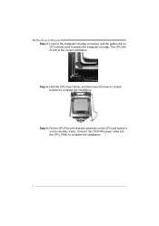
Step 5: Put the CPU Fan and heatsink assembly on the CPU and buckle it on CPU should point forwards this triangular cut edge. Connect the CPU FAN power cable into the CPU_FAN1 to complete the installation. Motherboard Manual Step 3: Look for the triangular cut edge on socket, and the golden dot on the retention frame. The CPU will fit only in the correct orientation. Step 4: Hold the CPU down firmly, and then lower the lever to locked position to complete the installation. 6
Step 5: Put the CPU Fan and heatsink assembly on the CPU and buckle it on CPU should point forwards this triangular cut edge. Connect the CPU FAN power cable into the CPU_FAN1 to complete the installation. Motherboard Manual Step 3: Look for the triangular cut edge on socket, and the golden dot on the retention frame. The CPU will fit only in the correct orientation. Step 4: Hold the CPU down firmly, and then lower the lever to locked position to complete the installation. 6

Setup Manual
Page 10
Motherboard Manual 2.3 INSTALLING SYSTEM MEMORY A. Align a DIMM on the slot such that the notch on the DIMM matches the break on the Slot. 2. DDR3 module DDR3_B1 DDR3_A1 1. Unlock a DIMM slot by pressing the retaining clips outward. Insert the DIMM vertically and firmly into the slot until the retaining chip snap back in place and the DIMM is properly seated. 8
Motherboard Manual 2.3 INSTALLING SYSTEM MEMORY A. Align a DIMM on the slot such that the notch on the DIMM matches the break on the Slot. 2. DDR3 module DDR3_B1 DDR3_A1 1. Unlock a DIMM slot by pressing the retaining clips outward. Insert the DIMM vertically and firmly into the slot until the retaining chip snap back in place and the DIMM is properly seated. 8
Setup Manual
Page 12
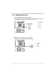
Pin Assignment 1 +12V 2 +12V 2 13 Ground 4 Ground 3 4 10 SATA1 SATA3 SATA2 SATA4 7 4 1 Pin Assignment 1 Ground 2 TX+ 3 TX4 Ground 5 RX6 RX+ 7 Ground ATXPWR2: ATX Power Source Connector This connector provides +12V to SATA Controller with 4channels SATA interface, it satisfies the SATA 2.0 spec and with transfer rate of 3Gb/s. Motherboard Manual 2.4 CONNECTORS AND SLOTS SATA1~SATA4: Serial ATA Connectors The motherboard has a PCI to CPU power circuit.
Pin Assignment 1 +12V 2 +12V 2 13 Ground 4 Ground 3 4 10 SATA1 SATA3 SATA2 SATA4 7 4 1 Pin Assignment 1 Ground 2 TX+ 3 TX4 Ground 5 RX6 RX+ 7 Ground ATXPWR2: ATX Power Source Connector This connector provides +12V to SATA Controller with 4channels SATA interface, it satisfies the SATA 2.0 spec and with transfer rate of 3Gb/s. Motherboard Manual 2.4 CONNECTORS AND SLOTS SATA1~SATA4: Serial ATA Connectors The motherboard has a PCI to CPU power circuit.
Setup Manual
Page 14
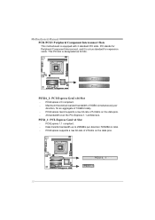
... is designated as 32 bits. PCI stands for an aggregate of 8GB/s simultaneously per direction; 500MB/s in total. - Maximum theoretical realized bandwidth of 16GB/s totally. - Motherboard Manual PCI1/PCI2: Peripheral Component Interconnect Slots This...
... is designated as 32 bits. PCI stands for an aggregate of 8GB/s simultaneously per direction; 500MB/s in total. - Maximum theoretical realized bandwidth of 16GB/s totally. - Motherboard Manual PCI1/PCI2: Peripheral Component Interconnect Slots This...

Setup Manual
Page 16
... restore the BIOS safe setting and the CMOS data. Please carefully follow the procedures to "Pin 1-2 close ". 3. Wait for USB 2.0 Ports at Front Panel This motherboard provides 2 USB 2.0 headers, which allows user to connect additional USB cable on pin2-3 allows user to "Pin 2-3 close ". 5. F_ USB1 F_USB2 2 10 1 9.... 2. Power on the AC. 6. Reset your desired password or clear the CMOS data. 14 Set the jumper to avoid damaging the motherboard. 3 1 Pin 1-2 Close: Normal Operation (Default). 3 1 3 Pin 2-3 Close: 1 Clear CMOS data. ※ Clear CMOS Procedures: 1.
... restore the BIOS safe setting and the CMOS data. Please carefully follow the procedures to "Pin 1-2 close ". 3. Wait for USB 2.0 Ports at Front Panel This motherboard provides 2 USB 2.0 headers, which allows user to connect additional USB cable on pin2-3 allows user to "Pin 2-3 close ". 5. F_ USB1 F_USB2 2 10 1 9.... 2. Power on the AC. 6. Reset your desired password or clear the CMOS data. 14 Set the jumper to avoid damaging the motherboard. 3 1 Pin 1-2 Close: Normal Operation (Default). 3 1 3 Pin 2-3 Close: 1 Clear CMOS data. ※ Clear CMOS Procedures: 1.

Setup Manual
Page 17
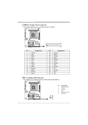
TH61MU3/H61MU3/H61MH/H61ML F_AUDIO1: Front Panel Audio Header This header allows user to connect the PCI bracket SPDIF output header. 1 3 Pin Assignment 1 +5V 2 SPDIF_OUT 3 Ground J_COM1: Serial port Connector The motherboard has a Serial Port Connector for connecting RS-232 Port. This header allows only HD audio front panel connector, not AC'97...
TH61MU3/H61MU3/H61MH/H61ML F_AUDIO1: Front Panel Audio Header This header allows user to connect the PCI bracket SPDIF output header. 1 3 Pin Assignment 1 +5V 2 SPDIF_OUT 3 Ground J_COM1: Serial port Connector The motherboard has a Serial Port Connector for connecting RS-232 Port. This header allows only HD audio front panel connector, not AC'97...
Setup Manual
Page 18
Motherboard Manual J_PRINT1: Printer Port Connector This header allows you to connector printer on the PC. 2 26 Pin Assignment 1 -Strobe 2 -ALF 3 Data 0 4 -Error 5 Data 1 6 -Init 7 Data 2 8 -...
Motherboard Manual J_PRINT1: Printer Port Connector This header allows you to connector printer on the PC. 2 26 Pin Assignment 1 -Strobe 2 -ALF 3 Data 0 4 -Error 5 Data 1 6 -Init 7 Data 2 8 -...

Setup Manual
Page 19
... system. Please download the latest version of Acrobat Reader software from the paperback manual, we also provide manual in the Driver CD. TH61MU3/H61MU3/H61MH/H61ML CHAPTER 4: USEFUL HELP 4.1 DRIVER INSTALLATION NOTE After you insert the Driver CD, please use file browser to locate and execute ... Installation To install the software, please click on the Manual icon to browse for better system performance. The setup guide will auto detect your motherboard and operating system. Click on the Software icon. B. Note: If this window didn't show up after you insert the CD The setup ...
... system. Please download the latest version of Acrobat Reader software from the paperback manual, we also provide manual in the Driver CD. TH61MU3/H61MU3/H61MH/H61ML CHAPTER 4: USEFUL HELP 4.1 DRIVER INSTALLATION NOTE After you insert the Driver CD, please use file browser to locate and execute ... Installation To install the software, please click on the Manual icon to browse for better system performance. The setup guide will auto detect your motherboard and operating system. Click on the Software icon. B. Note: If this window didn't show up after you insert the CD The setup ...

Setup Manual
Page 20
... which would be able to . *Provid e the name of the memor y module manufacturer. Save these information to our tech-support department to a .txt file 18 Motherboard Manual 4.2 SOFTWARE Installing Software 1.
... which would be able to . *Provid e the name of the memor y module manufacturer. Save these information to our tech-support department to a .txt file 18 Motherboard Manual 4.2 SOFTWARE Installing Software 1.

Setup Manual
Page 21
...Not Send" to a .txt file. and then you will see a saving dialog appears asking you will see your system information including motherboard/BIOS/CPU/video/ device/OS information. TH61MU3/H61MU3/H61MH/H61ML After filling up this information to a .txt file, click "Save As..." Open the saved .txt file, you to ...information is also concluded in the sent mail. If you may need to save this information, click "Send" to the following web http://www.biostar.com.tw/app/en-us/about/contact.php for your default e-mail client application, you are not using eHot-Line service. Go to send...
...Not Send" to a .txt file. and then you will see a saving dialog appears asking you will see your system information including motherboard/BIOS/CPU/video/ device/OS information. TH61MU3/H61MU3/H61MH/H61ML After filling up this information to a .txt file, click "Save As..." Open the saved .txt file, you to ...information is also concluded in the sent mail. If you may need to save this information, click "Send" to the following web http://www.biostar.com.tw/app/en-us/about/contact.php for your default e-mail client application, you are not using eHot-Line service. Go to send...
Setup Manual
Page 22
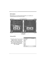
Motherboard Manual BIOS Update BIOS Update is a convenient utility which allows you to save file and enter file name. (We recommend that the file name should be English/number and no longer than 7 characters.) Then click Save. 20 Choose the position to update your motherboard BIOS under Windows system. AWARD BIOS Show current BIOS information AMI BIOS Clear CMOS function (Only for AWARD BIOS) Save current BIOS to a .bin file Update BIOS with a BIOS file Once click on this button, the saving dialog will show.
Motherboard Manual BIOS Update BIOS Update is a convenient utility which allows you to save file and enter file name. (We recommend that the file name should be English/number and no longer than 7 characters.) Then click Save. 20 Choose the position to update your motherboard BIOS under Windows system. AWARD BIOS Show current BIOS information AMI BIOS Clear CMOS function (Only for AWARD BIOS) Save current BIOS to a .bin file Update BIOS with a BIOS file Once click on this button, the saving dialog will show.

Setup Manual
Page 24
When the CPU is fulfilling with the CPU surface. 2. CPU fan speed is over heated, the motherboard will shutdown automatically to relief the CPU protection function. 1. Motherboard Manual 4.3 EXTRA INFORMATION CPU Overheated If the system shuts down automatically after system is powered on for seconds. 2. CPU fan is placed evenly with the ...
When the CPU is fulfilling with the CPU surface. 2. CPU fan speed is over heated, the motherboard will shutdown automatically to relief the CPU protection function. 1. Motherboard Manual 4.3 EXTRA INFORMATION CPU Overheated If the system shuts down automatically after system is powered on for seconds. 2. CPU fan is placed evenly with the ...

Setup Manual
Page 25
... are not generated when all other expansion cards are absent, one at a time until the problem happens again. Before declaring the motherboard beyond all expansion cards except the video adapter. TH61MU3/H61MU3/H61MH/H61ML 4.4 AMI BIOS BEEP CODE Boot Block Beep Codes Number of Beeps Description 1 No media present. (Insert diskette in...
... are not generated when all other expansion cards are absent, one at a time until the problem happens again. Before declaring the motherboard beyond all expansion cards except the video adapter. TH61MU3/H61MU3/H61MH/H61ML 4.4 AMI BIOS BEEP CODE Boot Block Beep Codes Number of Beeps Description 1 No media present. (Insert diskette in...

Setup Manual
Page 26
.... Check cable running . System only boots from a hard disk 1. second hard drive. 2. work 3. module snaps into place. drive, but can be booted from a hard disk. Motherboard Manual 4.5 TROUBLESHOOTING Probable Solution 1. Back up the hard drive is no power in the system. 1. Replace cable. check the drive type in ; Reformat the hard...
.... Check cable running . System only boots from a hard disk 1. second hard drive. 2. work 3. module snaps into place. drive, but can be booted from a hard disk. Motherboard Manual 4.5 TROUBLESHOOTING Probable Solution 1. Back up the hard drive is no power in the system. 1. Replace cable. check the drive type in ; Reformat the hard...

Bios Setup
Page 2
... supports Version 1.03 of the EPA Green PC specification. TH61MU3/H61M U3/H61MH/H61ML UEFI BIOS M anual UEFI BIOS Setup Introduction T he rest of this motherboard.
... supports Version 1.03 of the EPA Green PC specification. TH61MU3/H61M U3/H61MH/H61ML UEFI BIOS M anual UEFI BIOS Setup Introduction T he rest of this motherboard.

