
Setup Manual
Page 1
These limits are trademarks of their respective companies. The vendor makes no guarantee that interference will not be applied TH61MU3/H61MU3/H61MH/H61ML Setup Manual FCC Information and Copyright This equipment has been tested and found in accordance with the instructions, may cause harmful interference to... and product names are designed to provide reasonable protection against harmful interference in a particular installation. The content of this user's manual. This equipment generates, uses, and can radiate radio frequency energy and, if not installed and used in this user...
These limits are trademarks of their respective companies. The vendor makes no guarantee that interference will not be applied TH61MU3/H61MU3/H61MH/H61ML Setup Manual FCC Information and Copyright This equipment has been tested and found in accordance with the instructions, may cause harmful interference to... and product names are designed to provide reasonable protection against harmful interference in a particular installation. The content of this user's manual. This equipment generates, uses, and can radiate radio frequency energy and, if not installed and used in this user...

Setup Manual
Page 3
... and stable working environment with sufficient lighting. „ Always disconnect the computer from power outlet before operation. „ Before you for ATX Case X 1 User's Manual X 1 Fully Setup Driver CD X 1 USB 2.0 Cable X1 (optional) Serial ATA Power Cable X 1 (optional) Note: The package contents may be 0 ...board. „ Do not leave any safely grounded appliance, or use grounded wrist strap to area or your motherboard version. 1 TH61MU3/H61MU3/H61MH/H61ML CHAPTER 1: INTRODUCTION 1.1 BEFORE YOU START Thank you take the motherboard out from dangerous area, such as heat source, humid ...
... and stable working environment with sufficient lighting. „ Always disconnect the computer from power outlet before operation. „ Before you for ATX Case X 1 User's Manual X 1 Fully Setup Driver CD X 1 USB 2.0 Cable X1 (optional) Serial ATA Power Cable X 1 (optional) Note: The package contents may be 0 ...board. „ Do not leave any safely grounded appliance, or use grounded wrist strap to area or your motherboard version. 1 TH61MU3/H61MU3/H61MH/H61ML CHAPTER 1: INTRODUCTION 1.1 BEFORE YOU START Thank you take the motherboard out from dangerous area, such as heat source, humid ...

Setup Manual
Page 4
... Mb/s / 1Gb/s auto negotiation ALC662 Sound Codec 5.1 channels audio out High Definition Audio Integrated Serial ATA Controller Data transfer rates up to 3.0 Gb/s. Motherboard Manual 1.3 MOTHERBOARD FEATURES TH61MU3 / H61MU3 H61MH / H61ML Socket 1155 Socket 1155 Intel Core i7 / i5 / i3/ Pentium processor Intel Core i7 / i5 / i3/ Pentium processor Supports Execute Disable...
... Mb/s / 1Gb/s auto negotiation ALC662 Sound Codec 5.1 channels audio out High Definition Audio Integrated Serial ATA Controller Data transfer rates up to 3.0 Gb/s. Motherboard Manual 1.3 MOTHERBOARD FEATURES TH61MU3 / H61MU3 H61MH / H61ML Socket 1155 Socket 1155 Intel Core i7 / i5 / i3/ Pentium processor Intel Core i7 / i5 / i3/ Pentium processor Supports Execute Disable...

Setup Manual
Page 6
Motherboard Manual 1.5 MOTHERBOARD LAYOUT USBKB1 DDR3_B1 DDR3_A1 HDM I1 DVI1 Socket 1155 CPU1 CPU_FAN1 ATXPW R 1 VGA1 SATA1 SATA3 SATA2 SATA4 RJ45USB1 LAN AUDIO1 ATXPWR2 PEX16_1 PCI1 H61 BIOS PCI2 CODEC PEX1_1 Super I/O BAT1 J SPDIFOUT1 F_ AUDIO1 J_PRINT1 J_COM1 CIR1 F_USB1 F_USB2 JCMOS1 SYS_FAN1 PANEL1 Note: ■ represents the 1st pin. 4
Motherboard Manual 1.5 MOTHERBOARD LAYOUT USBKB1 DDR3_B1 DDR3_A1 HDM I1 DVI1 Socket 1155 CPU1 CPU_FAN1 ATXPW R 1 VGA1 SATA1 SATA3 SATA2 SATA4 RJ45USB1 LAN AUDIO1 ATXPWR2 PEX16_1 PCI1 H61 BIOS PCI2 CODEC PEX1_1 Super I/O BAT1 J SPDIFOUT1 F_ AUDIO1 J_PRINT1 J_COM1 CIR1 F_USB1 F_USB2 JCMOS1 SYS_FAN1 PANEL1 Note: ■ represents the 1st pin. 4
Setup Manual
Page 8
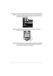
Connect the CPU FAN power cable into the CPU_FAN1 to complete the installation. Step 4: Hold the CPU down firmly, and then lower the lever to locked position to complete the installation. 6 Step 5: Put the CPU Fan and heatsink assembly on the CPU and buckle it on CPU should point forwards this triangular cut edge. The CPU will fit only in the correct orientation. Motherboard Manual Step 3: Look for the triangular cut edge on socket, and the golden dot on the retention frame.
Connect the CPU FAN power cable into the CPU_FAN1 to complete the installation. Step 4: Hold the CPU down firmly, and then lower the lever to locked position to complete the installation. 6 Step 5: Put the CPU Fan and heatsink assembly on the CPU and buckle it on CPU should point forwards this triangular cut edge. The CPU will fit only in the correct orientation. Motherboard Manual Step 3: Look for the triangular cut edge on socket, and the golden dot on the retention frame.

Setup Manual
Page 10
Align a DIMM on the slot such that the notch on the DIMM matches the break on the Slot. 2. Insert the DIMM vertically and firmly into the slot until the retaining chip snap back in place and the DIMM is properly seated. 8 Motherboard Manual 2.3 INSTALLING SYSTEM MEMORY A. DDR3 module DDR3_B1 DDR3_A1 1. Unlock a DIMM slot by pressing the retaining clips outward.
Align a DIMM on the slot such that the notch on the DIMM matches the break on the Slot. 2. Insert the DIMM vertically and firmly into the slot until the retaining chip snap back in place and the DIMM is properly seated. 8 Motherboard Manual 2.3 INSTALLING SYSTEM MEMORY A. DDR3 module DDR3_B1 DDR3_A1 1. Unlock a DIMM slot by pressing the retaining clips outward.
Setup Manual
Page 12
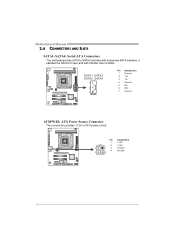
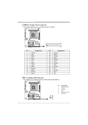
Motherboard Manual 2.4 CONNECTORS AND SLOTS SATA1~SATA4: Serial ATA Connectors The motherboard has a PCI to CPU power circuit. Pin Assignment 1 +12V 2 +12V 2 13 Ground 4 Ground 3 4 10 SATA1 SATA3 SATA2 SATA4 7 4 1 Pin Assignment 1 Ground 2 TX+ 3 TX4 Ground 5 RX6 RX+ 7 Ground ATXPWR2: ATX Power Source Connector This connector provides +12V to SATA Controller with 4channels SATA interface, it satisfies the SATA 2.0 spec and with transfer rate of 3Gb/s.
Motherboard Manual 2.4 CONNECTORS AND SLOTS SATA1~SATA4: Serial ATA Connectors The motherboard has a PCI to CPU power circuit. Pin Assignment 1 +12V 2 +12V 2 13 Ground 4 Ground 3 4 10 SATA1 SATA3 SATA2 SATA4 7 4 1 Pin Assignment 1 Ground 2 TX+ 3 TX4 Ground 5 RX6 RX+ 7 Ground ATXPWR2: ATX Power Source Connector This connector provides +12V to SATA Controller with 4channels SATA interface, it satisfies the SATA 2.0 spec and with transfer rate of 3Gb/s.
Setup Manual
Page 14
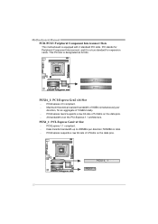
.... - PCI-Express 2.0 compliant. - P CI 1 PCI2 PEX16_1: PCI-Express Gen2 x16 Slot - Maximum theoretical realized bandwidth of 16GB/s totally. - PEX1_1: PCI-Express Gen2 x1 Slot - Motherboard Manual PCI1/PCI2: Peripheral Component Interconnect Slots This motherboard is a bus standard for expansion cards. PCI-Express 1.1 compliant. - PEX16_1 PEX1_1 12 PCI stands for Peripheral Component...
.... - PCI-Express 2.0 compliant. - P CI 1 PCI2 PEX16_1: PCI-Express Gen2 x16 Slot - Maximum theoretical realized bandwidth of 16GB/s totally. - PEX1_1: PCI-Express Gen2 x1 Slot - Motherboard Manual PCI1/PCI2: Peripheral Component Interconnect Slots This motherboard is a bus standard for expansion cards. PCI-Express 1.1 compliant. - PEX16_1 PEX1_1 12 PCI stands for Peripheral Component...

Setup Manual
Page 16
Reset your desired password or clear the CMOS data. 14 Motherboard Manual F_USB1/F_USB2: Headers for five seconds. 4. Remove AC power line. 2. Set the jumper to "Pin 2-3 close ". 5. Power on pin2-3 allows user to avoid damaging the ...
Reset your desired password or clear the CMOS data. 14 Motherboard Manual F_USB1/F_USB2: Headers for five seconds. 4. Remove AC power line. 2. Set the jumper to "Pin 2-3 close ". 5. Power on pin2-3 allows user to avoid damaging the ...
Setup Manual
Page 18
Motherboard Manual J_PRINT1: Printer Port Connector This header allows you to connector printer on the PC. 2 26 Pin Assignment 1 -Strobe 2 -ALF 3 Data 0 4 -Error 5 Data 1 6 -Init 7 Data 2 8 -Scltin 9 ...
Motherboard Manual J_PRINT1: Printer Port Connector This header allows you to connector printer on the PC. 2 26 Pin Assignment 1 -Strobe 2 -ALF 3 Data 0 4 -Error 5 Data 1 6 -Init 7 Data 2 8 -Scltin 9 ...

Setup Manual
Page 19
... installation program. Please download the latest version of Acrobat Reader software from the paperback manual, we also provide manual in the Driver CD. Software Installation To install the software, please click on the Driver icon. TH61MU3/H61MU3/H61MH/H61ML CHAPTER 4: USEFUL HELP 4.1 DRIVER INSTALLATION NOTE After you installed your operating... need Acrobat Reader to locate and execute the file SETUP.EXE under your optical drive and install the driver for available manual. Note: If this window didn't show up after you insert the Driver CD, please use file browser to open the...
... installation program. Please download the latest version of Acrobat Reader software from the paperback manual, we also provide manual in the Driver CD. Software Installation To install the software, please click on the Driver icon. TH61MU3/H61MU3/H61MH/H61ML CHAPTER 4: USEFUL HELP 4.1 DRIVER INSTALLATION NOTE After you installed your operating... need Acrobat Reader to locate and execute the file SETUP.EXE under your optical drive and install the driver for available manual. Note: If this window didn't show up after you insert the Driver CD, please use file browser to open the...

Setup Manual
Page 20
... i nformation which is a convenient utility that helps you fix the problem. Launching Software After the installation process, you must provide. Send the mail out. Motherboard Manual 4.2 SOFTWARE Installing Software 1.
... i nformation which is a convenient utility that helps you fix the problem. Launching Software After the installation process, you must provide. Send the mail out. Motherboard Manual 4.2 SOFTWARE Installing Software 1.
Setup Manual
Page 22
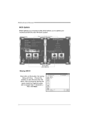
AWARD BIOS Show current BIOS information AMI BIOS Clear CMOS function (Only for AWARD BIOS) Save current BIOS to save file and enter file name. (We recommend that the file name should be English/number and no longer than 7 characters.) Then click Save. 20 Choose the position to a .bin file Update BIOS with a BIOS file Once click on this button, the saving dialog will show. Motherboard Manual BIOS Update BIOS Update is a convenient utility which allows you to update your motherboard BIOS under Windows system.
AWARD BIOS Show current BIOS information AMI BIOS Clear CMOS function (Only for AWARD BIOS) Save current BIOS to save file and enter file name. (We recommend that the file name should be English/number and no longer than 7 characters.) Then click Save. 20 Choose the position to a .bin file Update BIOS with a BIOS file Once click on this button, the saving dialog will show. Motherboard Manual BIOS Update BIOS Update is a convenient utility which allows you to update your motherboard BIOS under Windows system.
Setup Manual
Page 23
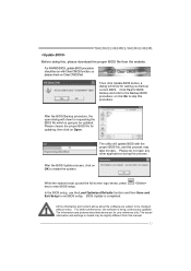
... procedure should be slightly different from the website. After the BIOS Update process, click on Clear CMOS first. TH61MU3/H61MU3/H61MH/H61ML Before doing this, please download the proper BIOS file from this manual. 21 Then click Update BIOS button, a dialog will update BIOS with Clear CMOS function, so please check on...
... procedure should be slightly different from the website. After the BIOS Update process, click on Clear CMOS first. TH61MU3/H61MU3/H61MH/H61ML Before doing this, please download the proper BIOS file from this manual. 21 Then click Update BIOS button, a dialog will update BIOS with Clear CMOS function, so please check on...

Setup Manual
Page 24
... this case, please double check: 1. CPU fan is placed evenly with the CPU speed. Clear the CMOS data. (See "Close CMOS Header: JCMOS1" section) 2. Motherboard Manual 4.3 EXTRA INFORMATION CPU Overheated If the system shuts down automatically after system is powered on the system again. 22 When the CPU is fulfilling with...
... this case, please double check: 1. CPU fan is placed evenly with the CPU speed. Clear the CMOS data. (See "Close CMOS Header: JCMOS1" section) 2. Motherboard Manual 4.3 EXTRA INFORMATION CPU Overheated If the system shuts down automatically after system is powered on the system again. 22 When the CPU is fulfilling with...

Setup Manual
Page 26
... are running from disk to boot from optical drive. Indicator light on , power indicator lights are lit, the DIMM, press down at any time. Motherboard Manual 4.5 TROUBLESHOOTING Probable Solution 1. the securely plugged in setup. Set master/slave jumpers correctly. System is Power LED does not shine; System only boots from a hard...
... are running from disk to boot from optical drive. Indicator light on , power indicator lights are lit, the DIMM, press down at any time. Motherboard Manual 4.5 TROUBLESHOOTING Probable Solution 1. the securely plugged in setup. Set master/slave jumpers correctly. System is Power LED does not shine; System only boots from a hard...

Bios Setup
Page 2
... developed by Microsoft, Intel and Toshiba. UEFI BIOS determines what a computer can do without accessing programs from a disk. T he purpose of this manual is supported. 1 T his AMI UEFI BIOS also supports Version 2.3 of the input and output devices such as defined in the AMI UEFI BIOS ...Setup program on this manual will to NVRAM. PCI Bus Support T his system controls most of the Intel PCI (Peripheral Component Interconnect) local bus specification. ACPI Support AMI...
... developed by Microsoft, Intel and Toshiba. UEFI BIOS determines what a computer can do without accessing programs from a disk. T he purpose of this manual is supported. 1 T his AMI UEFI BIOS also supports Version 2.3 of the input and output devices such as defined in the AMI UEFI BIOS ...Setup program on this manual will to NVRAM. PCI Bus Support T his system controls most of the Intel PCI (Peripheral Component Interconnect) local bus specification. ACPI Support AMI...
Bios Setup
Page 3
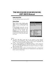
...utility, you can use these keys to select item and ch ange the settings. Notice z T he UEFI BIOS information described in this user's manual and any settings, please load the default settings to enter the UEFI BIOS setup utility. T he default UEFI BIOS settings apply for your referen... continuously updated. If the system becomes unstable after changing any system damage that particular menu are at the top right corner, and this manual is subject to ensure optimum perform ance of the motherboard. Using Setup When starting up the computer, press during the Power-On Self-Test...
...utility, you can use these keys to select item and ch ange the settings. Notice z T he UEFI BIOS information described in this user's manual and any settings, please load the default settings to enter the UEFI BIOS setup utility. T he default UEFI BIOS settings apply for your referen... continuously updated. If the system becomes unstable after changing any system damage that particular menu are at the top right corner, and this manual is subject to ensure optimum perform ance of the motherboard. Using Setup When starting up the computer, press during the Power-On Self-Test...
Bios Setup
Page 14
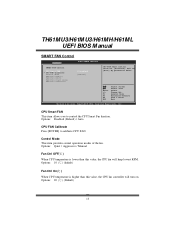
Options: Quiet / Aggressive / Manual Fan Ctrl OFF(℃ ) When CPU temperature is higher than this value, the CPU fan controller will keep lowest RPM. Options: 10 (℃) (default) Fan ... Control CPU Smart FAN > CPU FAN Calibrate Control Mode FAN Ctrl OFF(oC) FAN Ctrl ON(oC) FAN Ctrl Start value FAN Ctrl Sensitive [Disabled] [Manual] CPU FAN Smart control function. [Disabled]: Full ON [Auto]:By parameters below. Options: Disabled (Default) / Auto CPU FAN Calibrate Press [ENT ER] to control the...
Options: Quiet / Aggressive / Manual Fan Ctrl OFF(℃ ) When CPU temperature is higher than this value, the CPU fan controller will keep lowest RPM. Options: 10 (℃) (default) Fan ... Control CPU Smart FAN > CPU FAN Calibrate Control Mode FAN Ctrl OFF(oC) FAN Ctrl ON(oC) FAN Ctrl Start value FAN Ctrl Sensitive [Disabled] [Manual] CPU FAN Smart control function. [Disabled]: Full ON [Auto]:By parameters below. Options: Disabled (Default) / Auto CPU FAN Calibrate Press [ENT ER] to control the...

Bios Setup
Page 28
... in items of this menu may cause system to change voltage and clock of various devices. (Howev er, we suggest you enter UEFI BIOS Setup ====Manual CPU system==== Fixed CPU Ratio CPU Ratio CPU Base Clock(1/100 MHz) CPU Core Current Max(Amp) Power Limit 1 Value (Watt) Power Limit 2 Switch Power...
... in items of this menu may cause system to change voltage and clock of various devices. (Howev er, we suggest you enter UEFI BIOS Setup ====Manual CPU system==== Fixed CPU Ratio CPU Ratio CPU Base Clock(1/100 MHz) CPU Core Current Max(Amp) Power Limit 1 Value (Watt) Power Limit 2 Switch Power...

