Setup Manual
Page 1
... Declaration of the FCC Rules. The content of this publication, in part or in whole, is subject to radio communications. Duplication of this user's manual. H61MGC / H61MLC Setup Manual FCC Information and Copyright This equipment has been tested and found in writing.
... Declaration of the FCC Rules. The content of this publication, in part or in whole, is subject to radio communications. Duplication of this user's manual. H61MGC / H61MLC Setup Manual FCC Information and Copyright This equipment has been tested and found in writing.
Setup Manual
Page 3
CHAPTER 1: INTRODUCTION H61MGC / H61MLC 1.1 BEFORE YOU START Thank you take the motherboard out from dangerous area, such as heat source, humid air and water. „ The operating temperatures of ...
CHAPTER 1: INTRODUCTION H61MGC / H61MLC 1.1 BEFORE YOU START Thank you take the motherboard out from dangerous area, such as heat source, humid air and water. „ The operating temperatures of ...
Setup Manual
Page 4
... Slot x1 PCI Express Gen2 x16 Slot x1 Slots PCI Express Gen2 x1 Slot x2 PCI Express Gen2 x1 Slot x2 2 Motherboard Manual 1.3 MOTHERBOARD FEATURES H61MGC H61MLC Socket 1155 Socket 1155 Intel Core i7/i5/i3/Pentium/Celeron processor Intel Core i7/i5/i3/Pentium/Celeron processor Supports Execute Disable Bit / Enhanced...
... Slot x1 PCI Express Gen2 x16 Slot x1 Slots PCI Express Gen2 x1 Slot x2 PCI Express Gen2 x1 Slot x2 2 Motherboard Manual 1.3 MOTHERBOARD FEATURES H61MGC H61MLC Socket 1155 Socket 1155 Intel Core i7/i5/i3/Pentium/Celeron processor Intel Core i7/i5/i3/Pentium/Celeron processor Supports Execute Disable Bit / Enhanced...
Setup Manual
Page 5
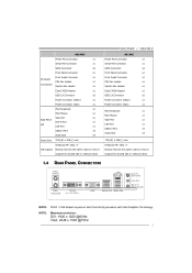
...x4 Audio Jack x3 Board Size 175 (W) x 226 (L) mm Windows XP / Vista / 7 OS Support Biostar reserves the right to add or remove support for any OS with or without notice H61MGC / H61MLC H61MLC Printer Port Connector x1 Serial Port Connector x1 SATA Connector x4 Front Panel Connector x1 Front Audio Connector...x1 PS/2 Mouse x1 VGA Port x1 LAN Port x1 USB2.0 Port x4 Audio Jack x3 175 (W) x 226 (L) mm Windows XP / Vista / 7 Biostar reserves the right to add or remove support for any OS with or without notice 1.4 REAR PANEL CONNECTORS P S/2 Mouse PS/2 Keyboard DVI-D (For...
...x4 Audio Jack x3 Board Size 175 (W) x 226 (L) mm Windows XP / Vista / 7 OS Support Biostar reserves the right to add or remove support for any OS with or without notice H61MGC / H61MLC H61MLC Printer Port Connector x1 Serial Port Connector x1 SATA Connector x4 Front Panel Connector x1 Front Audio Connector...x1 PS/2 Mouse x1 VGA Port x1 LAN Port x1 USB2.0 Port x4 Audio Jack x3 175 (W) x 226 (L) mm Windows XP / Vista / 7 Biostar reserves the right to add or remove support for any OS with or without notice 1.4 REAR PANEL CONNECTORS P S/2 Mouse PS/2 Keyboard DVI-D (For...
Setup Manual
Page 6
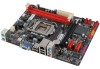
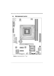
BIOS SATA1 JCMOS 1 SATA 2 SYS_ FAN1 SATA 3 SATA4 4 Motherboard Manual 1.5 MOTHERBOARD LAYOUT KBMS1 ATXPW R 2 CPU_FAN1 ( H61MGC ) DVI1 VGA1 DDR3_A1 DDR3_B1 Socket 1155 CP U 1 USB1 RJ45USB1 AUDIO1 F_AUDIO1 BAT1 PEX16_1 ATXPW R 1 CODEC PEX1_1 LAN H61 Super I/O PEX1_2 J_COM1 F_USB1 J_ PRINT1 F_USB2 PANEL1 Note: ■ represents the 1st pin.
BIOS SATA1 JCMOS 1 SATA 2 SYS_ FAN1 SATA 3 SATA4 4 Motherboard Manual 1.5 MOTHERBOARD LAYOUT KBMS1 ATXPW R 2 CPU_FAN1 ( H61MGC ) DVI1 VGA1 DDR3_A1 DDR3_B1 Socket 1155 CP U 1 USB1 RJ45USB1 AUDIO1 F_AUDIO1 BAT1 PEX16_1 ATXPW R 1 CODEC PEX1_1 LAN H61 Super I/O PEX1_2 J_COM1 F_USB1 J_ PRINT1 F_USB2 PANEL1 Note: ■ represents the 1st pin.
Setup Manual
Page 7
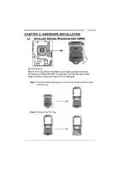
When the CPU is removed, cover the Pin Cap on the empty socket to ensure pin legs won't be damaged. Step 1: Pull the socket locking lever out from the socket and then raise the lever up. Step 2: Remove the Pin Cap. 5 H61MGC / H61MLC CHAPTER 2: HARDWARE INSTALLATION 2.1 INSTALLING CENTRAL PROCESSING UNIT (CPU) Special Notice: Remove Pin Cap before installation, and make good preservation for future use.
When the CPU is removed, cover the Pin Cap on the empty socket to ensure pin legs won't be damaged. Step 1: Pull the socket locking lever out from the socket and then raise the lever up. Step 2: Remove the Pin Cap. 5 H61MGC / H61MLC CHAPTER 2: HARDWARE INSTALLATION 2.1 INSTALLING CENTRAL PROCESSING UNIT (CPU) Special Notice: Remove Pin Cap before installation, and make good preservation for future use.
Setup Manual
Page 9
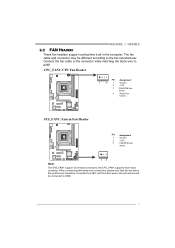
... rate sense 4 Smart Fan Control SYS_FAN1: System Fan Header Pin Assignment 1 Ground 2 +12V 3 FAN RPM rate sense 13 Note: The SYS_FAN1 support 3-pin head connectors; H61MGC / H61MLC 2.2 FAN HEADERS These fan headers support cooling-fans built in the computer. Connect the fan cable to the connector while matching the black wire to...
... rate sense 4 Smart Fan Control SYS_FAN1: System Fan Header Pin Assignment 1 Ground 2 +12V 3 FAN RPM rate sense 13 Note: The SYS_FAN1 support 3-pin head connectors; H61MGC / H61MLC 2.2 FAN HEADERS These fan headers support cooling-fans built in the computer. Connect the fan cable to the connector while matching the black wire to...
Setup Manual
Page 11
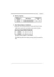
Dual Channel Status DDR3_A1 DDR3_B1 Disabled O X Disabled X O Enabled O O (O means memory installed; X, not installed.) The DRAM bus width of the same density in pairs, shown in the table. Dual Channel Memory Installation Please refer to the following requirements to activate Dual Channel function: Install memory module of the memory module must be the same(x8 or x16) 9 B. C. Memory Capacity H61MGC / H61MLC DIMM Socket Location DDR3_A1 DDR3_B1 DDR3 Module 512MB/1GB/2GB/4GB/8GB 512MB/1GB/2GB/4GB/8GB Total Memory Size Max is 16GB.
Dual Channel Status DDR3_A1 DDR3_B1 Disabled O X Disabled X O Enabled O O (O means memory installed; X, not installed.) The DRAM bus width of the same density in pairs, shown in the table. Dual Channel Memory Installation Please refer to the following requirements to activate Dual Channel function: Install memory module of the memory module must be the same(x8 or x16) 9 B. C. Memory Capacity H61MGC / H61MLC DIMM Socket Location DDR3_A1 DDR3_B1 DDR3 Module 512MB/1GB/2GB/4GB/8GB 512MB/1GB/2GB/4GB/8GB Total Memory Size Max is 16GB.
Setup Manual
Page 13
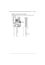
H61MGC / H61MLC ATXPWR1: ATX Power Source Connector This connector allows user to connect 24-pin power connector on the ATX power supply. 12 24 Pin Assignment 13 +3.3V 14 -12V 15 Ground 16 PS_ON 17 Ground 18 Ground 19 Ground 20 NC 21 +5V 22 +5V 23 +5V 24 Ground 1 13 Pin Assignment 1 +3.3V 2 +3.3V 3 Ground 4 +5V 5 Ground 6 +5V 7 Ground 8 PW_OK 9 Standby Voltage+5V 10 +12V 11 +12V 12 +3.3V 11
H61MGC / H61MLC ATXPWR1: ATX Power Source Connector This connector allows user to connect 24-pin power connector on the ATX power supply. 12 24 Pin Assignment 13 +3.3V 14 -12V 15 Ground 16 PS_ON 17 Ground 18 Ground 19 Ground 20 NC 21 +5V 22 +5V 23 +5V 24 Ground 1 13 Pin Assignment 1 +3.3V 2 +3.3V 3 Ground 4 +5V 5 Ground 6 +5V 7 Ground 8 PW_OK 9 Standby Voltage+5V 10 +12V 11 +12V 12 +3.3V 11
Setup Manual
Page 15
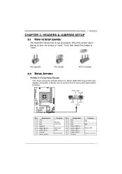
... LED (+) Power LED (+) Power LED (-) Power button Ground Function N/A N/A Power LED Power-on , Reset, HDD LED, Power LED, and speaker connection. POW_LED On/Off ++ - 9 16 1 8 +- H61MGC / H61MLC CHAPTER 3: HEADERS & JUMPERS SETUP 3.1 HOW TO SETUP JUMPERS The illustration shows how to connect the PC case's front panel switch functions. Pin opened Pin closed...
... LED (+) Power LED (+) Power LED (-) Power button Ground Function N/A N/A Power LED Power-on , Reset, HDD LED, Power LED, and speaker connection. POW_LED On/Off ++ - 9 16 1 8 +- H61MGC / H61MLC CHAPTER 3: HEADERS & JUMPERS SETUP 3.1 HOW TO SETUP JUMPERS The illustration shows how to connect the PC case's front panel switch functions. Pin opened Pin closed...
Setup Manual
Page 17
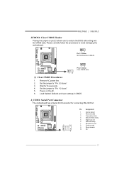
... CMOS data. ※ Clear CMOS Procedures: 1. Set the jumper to "Pin 2-3 close ". 5. J_COM1: Serial Port Connector The motherboard has a Serial Port Connector for five seconds. 4. H61MGC / H61MLC JCMOS1: Clear CMOS Header Placing the jumper on the AC. 6. Please carefully follow the procedures to send 9 Ring indicator 10 NC 15
... CMOS data. ※ Clear CMOS Procedures: 1. Set the jumper to "Pin 2-3 close ". 5. J_COM1: Serial Port Connector The motherboard has a Serial Port Connector for five seconds. 4. H61MGC / H61MLC JCMOS1: Clear CMOS Header Placing the jumper on the AC. 6. Please carefully follow the procedures to send 9 Ring indicator 10 NC 15
Setup Manual
Page 19
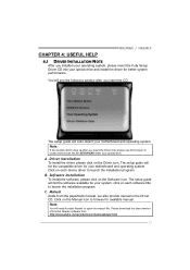
... file. Manual Aside from http://www.adobe.com /produ cts/a crobat /reads tep2 .html 17 B. Click on each software title to launch the installation program. H61MGC / H61MLC CHAPTER 4: USEFUL HELP 4.1 DRIVER INSTALLATION NOTE After you insert the Driver CD, please use file browser to locate and execute the file SETUP.EXE under...
... file. Manual Aside from http://www.adobe.com /produ cts/a crobat /reads tep2 .html 17 B. Click on each software title to launch the installation program. H61MGC / H61MLC CHAPTER 4: USEFUL HELP 4.1 DRIVER INSTALLATION NOTE After you insert the Driver CD, please use file browser to locate and execute the file SETUP.EXE under...
Setup Manual
Page 21
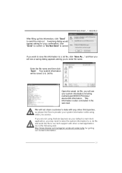
.... Enter the file name and then click "Save". Go to the following web http://www.biostar.com.tw/app/en-us/about/contact.php for your system information including motherboard/BIOS/CPU/video/ device/OS information. H61MGC / H61MLC If you are not using Outlook Express as your system information while using eHot-Line...
.... Enter the file name and then click "Save". Go to the following web http://www.biostar.com.tw/app/en-us/about/contact.php for your system information including motherboard/BIOS/CPU/video/ device/OS information. H61MGC / H61MLC If you are not using Outlook Express as your system information while using eHot-Line...
Setup Manual
Page 23
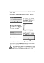
... applications during this process. BIOS Update is being continuously updated. After the BIOS Update process, click on OK to be slightly different from the website. H61MGC / H61MLC Before doing this, please download the proper BIOS file from this manual. 21 Click Update BIOS button, a dialog will update BIOS with the proper BIOS...
... applications during this process. BIOS Update is being continuously updated. After the BIOS Update process, click on OK to be slightly different from the website. H61MGC / H61MLC Before doing this, please download the proper BIOS file from this manual. 21 Click Update BIOS button, a dialog will update BIOS with the proper BIOS...

Setup Manual
Page 25
4.4 AMI BIOS BEEP CODE H61MGC / H61MLC Boot Block Beep Codes Number of Beeps Description 1 No media present. (Insert diskette in floppy drive A:) 2 "AMIBOOT.ROM" file not found in root directory of ...
4.4 AMI BIOS BEEP CODE H61MGC / H61MLC Boot Block Beep Codes Number of Beeps Description 1 No media present. (Insert diskette in floppy drive A:) 2 "AMIBOOT.ROM" file not found in root directory of ...
Setup Manual
Page 27
H61MGC / H61MLC This page is intentionally left blank. 25
H61MGC / H61MLC This page is intentionally left blank. 25
Setup Manual
Page 44
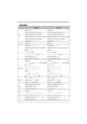
Motherboard Manual JAPANESE H61MGC H61MLC Socket 1155 Socket 1155 Intel Core i7/i5/i3/Pentium/Celeron Intel Core i7/i5/i3/Pentium/Celeron Execute Disable Bit / Enhanced Intel Execute Disable ...
Motherboard Manual JAPANESE H61MGC H61MLC Socket 1155 Socket 1155 Intel Core i7/i5/i3/Pentium/Celeron Intel Core i7/i5/i3/Pentium/Celeron Execute Disable Bit / Enhanced Intel Execute Disable ...