
GeForce 6100-M9 user's manual
Page 4
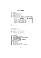
GeForce 6100-M9 System Memory Supports Dual Channel DDR.. DIMMB2 128MB/256MB/512MB/1GB *1 On-board IDE Two on-board connectors support 4 IDE disk drives. Data transfer rates ... in total. Four serial ATA connectors support 2 SATA devices. Supports 2 serial ATA (SATA) ports. - Supports 10 Mb/s and 100 Mb/s auto-negotiation. Supports ACPI, PCI power management. Onboard AC'97 Sound Codec Chip: ALC655 Support 6 channels.
GeForce 6100-M9 System Memory Supports Dual Channel DDR.. DIMMB2 128MB/256MB/512MB/1GB *1 On-board IDE Two on-board connectors support 4 IDE disk drives. Data transfer rates ... in total. Four serial ATA connectors support 2 SATA devices. Supports 2 serial ATA (SATA) ports. - Supports 10 Mb/s and 100 Mb/s auto-negotiation. Supports ACPI, PCI power management. Onboard AC'97 Sound Codec Chip: ALC655 Support 6 channels.

GeForce 6100-M9 user's manual
Page 8
... FAN RPM rate sense 1 3 JSFAN1 Note: The JCFAN1 and JSFAN1 support 3-pin head connector. The fan cable and connector may be connected to GND. 6 GeForce 6100-M9 Step 4: Hold the CPU down firmly, and then close the lever toward direct B to pin#1. Connect the fan cable to the connector while matching the... black wire to complete the installation. Connect the CPU FAN power cable to the fan manufacturer. When connecting with wires onto connectors, please note that the red wire is the positive and should be ...
... FAN RPM rate sense 1 3 JSFAN1 Note: The JCFAN1 and JSFAN1 support 3-pin head connector. The fan cable and connector may be connected to GND. 6 GeForce 6100-M9 Step 4: Hold the CPU down firmly, and then close the lever toward direct B to pin#1. Connect the fan cable to the connector while matching the... black wire to complete the installation. Connect the CPU FAN power cable to the fan manufacturer. When connecting with wires onto connectors, please note that the red wire is the positive and should be ...

GeForce 6100-M9 user's manual
Page 13
... panel (JUSB2/JUSB3) are powered by +5V standby voltage. JUSBV1 1 3 1 3 1 3 Pin 1-2 close (Default) JUSBV2 1 3 1 3 31 Pin 2-3 close ", if not, that means the jumper is "open". JUSBV2: USB ports at JUSB1 and JUSBLAN1 are powered by +5V standby voltage. GeForce 6100-M9 CHAPTER 3: HEADERS & JUMPERS ...SETUP 3.1 HOW TO SETUP JUMPERS The illustration shows how to support this function "Power-On system via USB device," "JUSBV1/ JUSBV2" jumper cap ...
... panel (JUSB2/JUSB3) are powered by +5V standby voltage. JUSBV1 1 3 1 3 1 3 Pin 1-2 close (Default) JUSBV2 1 3 1 3 31 Pin 2-3 close ", if not, that means the jumper is "open". JUSBV2: USB ports at JUSB1 and JUSBLAN1 are powered by +5V standby voltage. GeForce 6100-M9 CHAPTER 3: HEADERS & JUMPERS ...SETUP 3.1 HOW TO SETUP JUMPERS The illustration shows how to support this function "Power-On system via USB device," "JUSBV1/ JUSBV2" jumper cap ...

GeForce 6100-M9 user's manual
Page 14
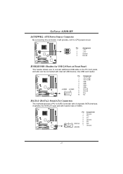
... Connector This connector allows user to support this function "Power-on system via keyboard and mouse", "JKBV1" jumper cap should be placed on the ATX power supply. Note: In order to connect 24-pin power connector on Pin 2-3. GeForce 6100-M9 JKBV1: Power Source Header for PS/2 Keyboard and Mouse 13 1 3 Pin 1-2 Close +5V for PS/2 keyboard...
... Connector This connector allows user to support this function "Power-on system via keyboard and mouse", "JKBV1" jumper cap should be placed on the ATX power supply. Note: In order to connect 24-pin power connector on Pin 2-3. GeForce 6100-M9 JKBV1: Power Source Header for PS/2 Keyboard and Mouse 13 1 3 Pin 1-2 Close +5V for PS/2 keyboard...
GeForce 6100-M9 user's manual
Page 15
... Panel This header allows user to SATA Controller with 2 channels SATA interface, it will provide +12V to CPU power circuit. Pin Assignment 1 Ground 2 TX+ 3 TX- 4 Ground 147 5 RX6 RX+ 7 Ground JSATA1 13 GeForce 6100-M9 JATXPWR2: ATX Power Source Connector By connecting this connector, it satisfies the SATA 2.0 spec and with internal USB devices, like...
... Panel This header allows user to SATA Controller with 2 channels SATA interface, it will provide +12V to CPU power circuit. Pin Assignment 1 Ground 2 TX+ 3 TX- 4 Ground 147 5 RX6 RX+ 7 Ground JSATA1 13 GeForce 6100-M9 JATXPWR2: ATX Power Source Connector By connecting this connector, it satisfies the SATA 2.0 spec and with internal USB devices, like...
GeForce 6100-M9 user's manual
Page 16
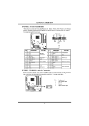
... Key IrDA Connector 20 Key 22 Ground 24 IRRX Function Sleep button N/A Power LED Power-on , Reset, HDD LED, Power LED, Sleep button, speaker and IrDA Connection. PWR_LED SLP On/Off ++ 2 1 +- GeForce 6100-M9 JPANEL1: Front Panel Header This 24-pin connector includes Power-on button IrDA Connector JCDIN1: CD-ROM Audio-in Connector This connector allows...
... Key IrDA Connector 20 Key 22 Ground 24 IRRX Function Sleep button N/A Power LED Power-on , Reset, HDD LED, Power LED, Sleep button, speaker and IrDA Connection. PWR_LED SLP On/Off ++ 2 1 +- GeForce 6100-M9 JPANEL1: Front Panel Header This 24-pin connector includes Power-on button IrDA Connector JCDIN1: CD-ROM Audio-in Connector This connector allows...

GeForce 6100-M9 user's manual
Page 17
Pin Assignment 1 Case open status. GeForce 6100-M9 JAUDIO2: Front Panel Audio Header This header allows user to monitor PC case open signal 2 Ground 1 2 15 If the signal has been triggered, it will ... record to the CMOS and show the message on back panel audio connectors. Pin Assignment 1 Mic-in/Stereo MIC-in R 2 Ground 3 Stereo MIC-in L 4 Audio power 5 Right line-out/ Speaker-out Right 1 2 6 Right line-out/ Speaker-out Right 7 Reserved 8 Key 9 Left line-out/ 13 14 Speaker-out Left 10 Left line...
Pin Assignment 1 Case open status. GeForce 6100-M9 JAUDIO2: Front Panel Audio Header This header allows user to monitor PC case open signal 2 Ground 1 2 15 If the signal has been triggered, it will ... record to the CMOS and show the message on back panel audio connectors. Pin Assignment 1 Mic-in/Stereo MIC-in R 2 Ground 3 Stereo MIC-in L 4 Audio power 5 Right line-out/ Speaker-out Right 1 2 6 Right line-out/ Speaker-out Right 7 Reserved 8 Key 9 Left line-out/ 13 14 Speaker-out Left 10 Left line...
GeForce 6100-M9 user's manual
Page 18
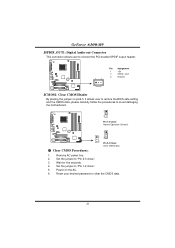
Wait for five seconds. 4. GeForce 6100-M9 JSPDIF_OUT1: Digital Audio-out Connector This connector allows user to connect the PCI bracket SPDIF output header. 1 3 Pin Assignment 1 +5V 2 SPDIF_OUT 3 Ground JCMOS1: Clear CMOS ... data. 16 Set the jumper to avoid damaging the motherboard. 1 3 Pin 1-2 Close: Normal Operation (Default). 1 13 3 Pin 2-3 Close: Clear CMOS data. ※ Clear CMOS Procedures: 1. Power on pin2-3, it allows user to restore the BIOS safe setting and the CMOS data, please carefully follow the procedures to "Pin 2-3 close ". 5. Remove AC...
Wait for five seconds. 4. GeForce 6100-M9 JSPDIF_OUT1: Digital Audio-out Connector This connector allows user to connect the PCI bracket SPDIF output header. 1 3 Pin Assignment 1 +5V 2 SPDIF_OUT 3 Ground JCMOS1: Clear CMOS ... data. 16 Set the jumper to avoid damaging the motherboard. 1 3 Pin 1-2 Close: Normal Operation (Default). 1 13 3 Pin 2-3 Close: Clear CMOS data. ※ Clear CMOS Procedures: 1. Power on pin2-3, it allows user to restore the BIOS safe setting and the CMOS data, please carefully follow the procedures to "Pin 2-3 close ". 5. Remove AC...
GeForce 6100-M9 user's manual
Page 20
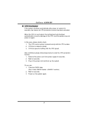
... is placed evenly with the CPU speed. CPU fan speed is rotated normally. 3. Wait for seconds. 2. GeForce 6100-M9 B. After confirmed, please follow steps below to avoid a damage of the CPU, and the system may not power on again. Wait for seconds, that means the CPU protection function has been activated. CPU fan is...
... is placed evenly with the CPU speed. CPU fan speed is rotated normally. 3. Wait for seconds. 2. GeForce 6100-M9 B. After confirmed, please follow steps below to avoid a damage of the CPU, and the system may not power on again. Wait for seconds, that means the CPU protection function has been activated. CPU fan is...
GeForce 6100-M9 user's manual
Page 21
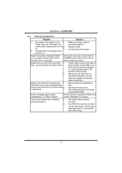
...board. Indicator light on keyboard does not turn 2. drive, can be booted from optical drive. 2. inside power supply does not turn on , power indicator lights are securely plugged in . Re-install applications and data using backup disks. on both ends are .... All hard disks are capable of the DIMM, press down at all 1. Review system's equipment. Make sure power cable is impossible. is Power light don't illuminate, fan securely plugged in ; GeForce 6100-M9 4.3 TROUBLESHOOTING Problem Solution 1. Backing up data and applications files.
...board. Indicator light on keyboard does not turn 2. drive, can be booted from optical drive. 2. inside power supply does not turn on , power indicator lights are securely plugged in . Re-install applications and data using backup disks. on both ends are .... All hard disks are capable of the DIMM, press down at all 1. Review system's equipment. Make sure power cable is impossible. is Power light don't illuminate, fan securely plugged in ; GeForce 6100-M9 4.3 TROUBLESHOOTING Problem Solution 1. Backing up data and applications files.
GeForce 6100-M9 user's manual
Page 22
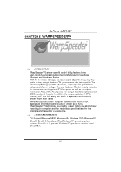
... one . 5.2 SYSTEM REQUIREMENT OS Support: Windows 98 SE, Windows Me, Windows 2000, Windows XP DirectX: DirectX 8.1 or above. (The Windows XP operating system includes DirectX 8.1. GeForce 6100-M9 CHAPTER 5: WARPSPEEDER™ 5.1 INTRODUCTION [WarpSpeeder™], a new powerful control utility, features three user-friendly functions including Overclock Manager, Overvoltage Manager, and Hardware Monitor.
... one . 5.2 SYSTEM REQUIREMENT OS Support: Windows 98 SE, Windows Me, Windows 2000, Windows XP DirectX: DirectX 8.1 or above. (The Windows XP operating system includes DirectX 8.1. GeForce 6100-M9 CHAPTER 5: WARPSPEEDER™ 5.1 INTRODUCTION [WarpSpeeder™], a new powerful control utility, features three user-friendly functions including Overclock Manager, Overvoltage Manager, and Hardware Monitor.
BIOS SETUP MANUAL
Page 1
GeForce 6100-M9 BIOS Setup BIOS Setup 1 1 Main Menu ...3 2 Standard CMOS Features 6 3 Advanced BIOS Features 9 4 Advanced Chipset Features 14 5 Integrated Peripherals 17 6 Power Management Setup 23 7 PnP/PCI Configurations 26 8 PC Health Status ...29 9 Frequency/Voltage Control 31 i
GeForce 6100-M9 BIOS Setup BIOS Setup 1 1 Main Menu ...3 2 Standard CMOS Features 6 3 Advanced BIOS Features 9 4 Advanced Chipset Features 14 5 Integrated Peripherals 17 6 Power Management Setup 23 7 PnP/PCI Configurations 26 8 PC Health Status ...29 9 Frequency/Voltage Control 31 i
BIOS SETUP MANUAL
Page 2
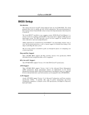
...the Plug and Play Version 1.0A specification. APM Support These AWARD BIOS supports Version 1.1&1.2 of Advanced Configuration and Power interface specification (ACPI). Power to the hard disk drives and video monitors can be managed by Microsoft, Intel and Toshiba. 1 This ...manual is a custom version of the chipset controlling the entire system. Power management features are supported. Sleep and Suspend power management modes are implemented via the System Management Interrupt (SMI). GeForce 6100-M9 BIOS Setup Introduction This manual discussed Award™ Setup program built ...
...the Plug and Play Version 1.0A specification. APM Support These AWARD BIOS supports Version 1.1&1.2 of Advanced Configuration and Power interface specification (ACPI). Power to the hard disk drives and video monitors can be managed by Microsoft, Intel and Toshiba. 1 This ...manual is a custom version of the chipset controlling the entire system. Power management features are supported. Sleep and Suspend power management modes are implemented via the System Management Interrupt (SMI). GeForce 6100-M9 BIOS Setup Introduction This manual discussed Award™ Setup program built ...
BIOS SETUP MANUAL
Page 5
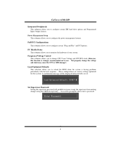
GeForce 6100-M9 Integrated Peripherals This submenu allows you to configure the power management features. Not properly change the voltage and clock may cause the CPU or M/B damage!) Load Optimized Defaults This selection allows you to use. ...change CPU Vcore Voltage and CPU/PCI clock. (However, this system. Set Supervisor Password Setting the supervisor password will be prompted with the boot sequence. Power Management Setup This submenu allows you to enter a password. 4 You will be displayed before defaults are factory settings optimized for this function is having ...
GeForce 6100-M9 Integrated Peripherals This submenu allows you to configure the power management features. Not properly change the voltage and clock may cause the CPU or M/B damage!) Load Optimized Defaults This selection allows you to use. ...change CPU Vcore Voltage and CPU/PCI clock. (However, this system. Set Supervisor Password Setting the supervisor password will be prompted with the boot sequence. Power Management Setup This submenu allows you to enter a password. 4 You will be displayed before defaults are factory settings optimized for this function is having ...
BIOS SETUP MANUAL
Page 13
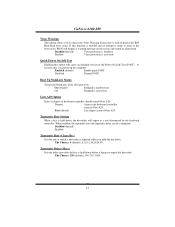
...controller. On (default) Numpad is arrow keys. Off Numpad is number keys. The Choices: 250 (default), 500, 750, 1000. 12 GeForce 6100-M9 Virus Warning This option allows you to choose the Virus Warning feature that is used to execute after you hold the key down. Disabled (...to repeat the keystroke. When enabled, the typematic rate and typematic delay can be configured. Typematic Delay (Msec) Sets the delay time after power on the screen and sound an alarm beep. If this option will display a warning message on . Disabled (default) Enabled Typematic Rate ...
...controller. On (default) Numpad is arrow keys. Off Numpad is number keys. The Choices: 250 (default), 500, 750, 1000. 12 GeForce 6100-M9 Virus Warning This option allows you to choose the Virus Warning feature that is used to execute after you hold the key down. Disabled (...to repeat the keystroke. When enabled, the typematic rate and typematic delay can be configured. Typematic Delay (Msec) Sets the delay time after power on the screen and sound an alarm beep. If this option will display a warning message on . Disabled (default) Enabled Typematic Rate ...
BIOS SETUP MANUAL
Page 21
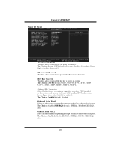
...Ctrl-F4, Ctrl-F5, Ctrl-F6, Ctrl-F7, Ctrl-F8, Ctrl-F9, Ctrl-F10, Ctrl-F11, Ctrl-F12. KB Power On Password This item allows you to choose the power on function. Onboard FDC Controller Select Enabled if your system has a floppy disk controller (FDC) installed on system. Onboard Serial Port...), 2F8/IRQ3, 3E8/IRQ4, 2E8/IRQ3, Auto. The Choices: Disabled (default), 2F8/IRQ3, 3F8/IRQ4, 3E8/IRQ4, 2E8/IRQ3, Auto. 20 Super IO Device GeForce 6100-M9 POWER ON Function This item allows you to enter a password with at least 5 characters. If install and FDC or the system has no floppy drive, select...
...Ctrl-F4, Ctrl-F5, Ctrl-F6, Ctrl-F7, Ctrl-F8, Ctrl-F9, Ctrl-F10, Ctrl-F11, Ctrl-F12. KB Power On Password This item allows you to choose the power on function. Onboard FDC Controller Select Enabled if your system has a floppy disk controller (FDC) installed on system. Onboard Serial Port...), 2F8/IRQ3, 3E8/IRQ4, 2E8/IRQ3, Auto. The Choices: Disabled (default), 2F8/IRQ3, 3F8/IRQ4, 3E8/IRQ4, 2E8/IRQ3, Auto. 20 Super IO Device GeForce 6100-M9 POWER ON Function This item allows you to enter a password with at least 5 characters. If install and FDC or the system has no floppy drive, select...
BIOS SETUP MANUAL
Page 23
GeForce 6100-M9 AC97 Audio This option allows you to enable or disable Onboard LAN Boot ROM. The Choices: Disabled (default), Enabled. MAC Media Interface The Choices: Pin Strap (default).MII. If your system will reboot after a power fail or interrupts occurs. POWER After PWR-Fail This setting ... where the drive can support. The Choices: Enabled (default), Disabled. The Choices: Auto (default), Disabled. Off Leaves the computer in the power off state. Former-Sts Restores the system to enable or disable the Onboard 1394 Controller. The Choices: Off (default), On, Former-Sts....
GeForce 6100-M9 AC97 Audio This option allows you to enable or disable Onboard LAN Boot ROM. The Choices: Disabled (default), Enabled. MAC Media Interface The Choices: Pin Strap (default).MII. If your system will reboot after a power fail or interrupts occurs. POWER After PWR-Fail This setting ... where the drive can support. The Choices: Enabled (default), Disabled. The Choices: Auto (default), Disabled. Off Leaves the computer in the power off state. Former-Sts Restores the system to enable or disable the Onboard 1394 Controller. The Choices: Off (default), On, Former-Sts....

BIOS SETUP MANUAL
Page 24
GeForce 6100-M9 6 Power Management Setup The Power Management Setup Menu allows you to select the suspend type under the ACPI operating system. Power Management Setup ACPI function This item displays the status of power saving and is directly related to the following modes: 1.HDD Power Down. 2.Suspend Mode. Power Saving Minimum power management. Suspend Mode = 1 hr. Figure 6. HDD Power Down = 15...
GeForce 6100-M9 6 Power Management Setup The Power Management Setup Menu allows you to select the suspend type under the ACPI operating system. Power Management Setup ACPI function This item displays the status of power saving and is directly related to the following modes: 1.HDD Power Down. 2.Suspend Mode. Power Saving Minimum power management. Suspend Mode = 1 hr. Figure 6. HDD Power Down = 15...
BIOS SETUP MANUAL
Page 25
When not disabled, each mode individually. and disable. V/H SYNC+Blank This selection will power down and after a set each of system inactivity. The Choices: Stop Grant, PwrOn Suspend. HDD Power Down When enabled, the hard disk drive will cause the system to turn off the vertical ...which the monitor is from 1 min. WOL (PME#) From Soft-Off The Choices: Disabled (default), Enabled. DPMS (default) Initial display power management signaling. GeForce 6100-M9 Max. except for more than 4 seconds forces the system to 15 min. The Choices: Delay 4 Sec, Instant-Off (default). Video...
When not disabled, each mode individually. and disable. V/H SYNC+Blank This selection will power down and after a set each of system inactivity. The Choices: Stop Grant, PwrOn Suspend. HDD Power Down When enabled, the hard disk drive will cause the system to turn off the vertical ...which the monitor is from 1 min. WOL (PME#) From Soft-Off The Choices: Disabled (default), Enabled. DPMS (default) Initial display power management signaling. GeForce 6100-M9 Max. except for more than 4 seconds forces the system to 15 min. The Choices: Delay 4 Sec, Instant-Off (default). Video...

BIOS SETUP MANUAL
Page 26
GeForce 6100-M9 USB Resume from S3/S4 The Choices: Disabled (default), Enabled. The Choices: Disabled (default), Enabled. The Choices: Disabled (default), Auto. 25 K8 Cool'n' Quiet Control This function supports AMD Cool 'n' Quick function. Power-On by Alarm When you select Enabled, an alarm returns the system to Full ON state.
GeForce 6100-M9 USB Resume from S3/S4 The Choices: Disabled (default), Enabled. The Choices: Disabled (default), Enabled. The Choices: Disabled (default), Auto. 25 K8 Cool'n' Quiet Control This function supports AMD Cool 'n' Quick function. Power-On by Alarm When you select Enabled, an alarm returns the system to Full ON state.


