Setup Manual
Page 2
... 1 1.2 Package Checklist 1 1.3 Motherboard Features 2 1.4 Rear Panel Connectors 3 1.5 Motherboard Layout 4 Chapter 2: Hardware Installation 5 2.1 Installing Central Processing Unit (CPU 5 2.2 FAN Headers 7 2.3 Installing System Memory 8 2.4 Connectors and Slots 10 Chapter 3: Headers & Jumpers Setup 12 3.1 How to Setup Jumpers 12 3.2 Detail Settings 12 Chapter 4: Useful Help 18 4.1 Driver Installation Note 18 4.2 Software 19 4.3 Extra Information 23 4.4 AMI BIOS...
... 1 1.2 Package Checklist 1 1.3 Motherboard Features 2 1.4 Rear Panel Connectors 3 1.5 Motherboard Layout 4 Chapter 2: Hardware Installation 5 2.1 Installing Central Processing Unit (CPU 5 2.2 FAN Headers 7 2.3 Installing System Memory 8 2.4 Connectors and Slots 10 Chapter 3: Headers & Jumpers Setup 12 3.1 How to Setup Jumpers 12 3.2 Detail Settings 12 Chapter 4: Useful Help 18 4.1 Driver Installation Note 18 4.2 Software 19 4.3 Extra Information 23 4.4 AMI BIOS...
Setup Manual
Page 14
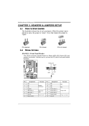
Pin opened Pin closed 3.2 DETAIL SETTINGS Pin1-2 closed JPANEL1: Front Panel Header This 16-pin connector includes Power-on button 12 PWR_LED On/Off 9 ++ 16 1 + 8 SPK RST HLED Pin Assignment 1 +5V 2 N/A 3 N/A 4 Speaker 5 HDD LED (+) 6 HDD LED ... (-) Power button Ground Function N/A N/A Power LED Power-on , Reset, HDD LED, Power LED, and speaker connection. It allows user to set up jumpers. Motherboard Manual CHAPTER 3: HEADERS & JUMPERS SETUP 3.1 HOW TO SETUP JUMPERS The illustration shows how to connect the PC case's front panel switch functions. - When the...
Pin opened Pin closed 3.2 DETAIL SETTINGS Pin1-2 closed JPANEL1: Front Panel Header This 16-pin connector includes Power-on button 12 PWR_LED On/Off 9 ++ 16 1 + 8 SPK RST HLED Pin Assignment 1 +5V 2 N/A 3 N/A 4 Speaker 5 HDD LED (+) 6 HDD LED ... (-) Power button Ground Function N/A N/A Power LED Power-on , Reset, HDD LED, Power LED, and speaker connection. It allows user to set up jumpers. Motherboard Manual CHAPTER 3: HEADERS & JUMPERS SETUP 3.1 HOW TO SETUP JUMPERS The illustration shows how to connect the PC case's front panel switch functions. - When the...
Setup Manual
Page 17
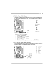
... Wait for five seconds. 4. SATA4 SATA3 SATA1 SATA2 Pin Assignment 1 Ground 2 TX+ 3 TX4 Ground 5 RX6 RX+ 7 Ground 7 41 15 Set the jumper to "Pin 2-3 close ". 5. SATA1~SATA4: Serial ATA Connectors The motherboard has a PCI to avoid damaging the motherboard. 3 1 Pin 1-2 Close: Normal Operation ...Pin 2-3 Close: 1 Clear CMOS data. ※ Clear CMOS Procedures: 1. Power on pin2-3 allows user to "Pin 1-2 close ". 3. Set the jumper to restore the BIOS safe setting and the CMOS data. Remove AC power line. 2. G41-M7 JCMOS1: Clear CMOS Header Placing the jumper on the AC. 6.
... Wait for five seconds. 4. SATA4 SATA3 SATA1 SATA2 Pin Assignment 1 Ground 2 TX+ 3 TX4 Ground 5 RX6 RX+ 7 Ground 7 41 15 Set the jumper to "Pin 2-3 close ". 5. SATA1~SATA4: Serial ATA Connectors The motherboard has a PCI to avoid damaging the motherboard. 3 1 Pin 1-2 Close: Normal Operation ...Pin 2-3 Close: 1 Clear CMOS data. ※ Clear CMOS Procedures: 1. Power on pin2-3 allows user to "Pin 1-2 close ". 3. Set the jumper to restore the BIOS safe setting and the CMOS data. Remove AC power line. 2. G41-M7 JCMOS1: Clear CMOS Header Placing the jumper on the AC. 6.


