Setup Manual
Page 2
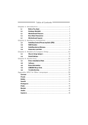
Table of Contents Chapter 1: Introduction 1 1.1 Before You Start 1 1.2 Package Checklist 1 1.3 Motherboard Features 2 1.4 Rear Panel Connectors 3 1.5 Motherboard Layout 4 Chapter 2: Hardware Installation 5 2.1 Installing Central Processing Unit (CPU 5 2.2 FAN Headers 7 2.3 Installing System Memory 8 2.4... Note 18 4.2 Software 19 4.3 Extra Information 23 4.4 AMI BIOS Beep Code 25 4.5 Troubleshooting 26 Appendix: SPEC In Other Languages 28 German...28 French ...30 Italian...32 Spanish ...34 Portuguese ...36 Polish...38 Russian ...40 Arabic...42 Japanese...
Table of Contents Chapter 1: Introduction 1 1.1 Before You Start 1 1.2 Package Checklist 1 1.3 Motherboard Features 2 1.4 Rear Panel Connectors 3 1.5 Motherboard Layout 4 Chapter 2: Hardware Installation 5 2.1 Installing Central Processing Unit (CPU 5 2.2 FAN Headers 7 2.3 Installing System Memory 8 2.4... Note 18 4.2 Software 19 4.3 Extra Information 23 4.4 AMI BIOS Beep Code 25 4.5 Troubleshooting 26 Appendix: SPEC In Other Languages 28 German...28 French ...30 Italian...32 Spanish ...34 Portuguese ...36 Polish...38 Russian ...40 Arabic...42 Japanese...
Setup Manual
Page 4
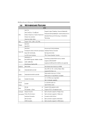
... Floppy drives x1 Each connector supports 1 Printer port x1 Connects to 3.0 Gb/s. Motherboard Manual 1.3 MOTHERBOARD FEATURES SPEC LGA 775 Supports Hyper-Threading / Execute Disable Bit / Intel Core2Duo / Core2Quad .../ Enhanced Intel SpeedStep® / Intel Architecture-64 / CPU Pentium Dual-Core / Celeron Dual-Core / Extended Memory 64 Technology / Virtualization Celeron 4xx processor Technology (Maximum Watt: 95W) FSB Support 800 / 1066 / 1333 MHz Chipset Intel G41...
... Floppy drives x1 Each connector supports 1 Printer port x1 Connects to 3.0 Gb/s. Motherboard Manual 1.3 MOTHERBOARD FEATURES SPEC LGA 775 Supports Hyper-Threading / Execute Disable Bit / Intel Core2Duo / Core2Quad .../ Enhanced Intel SpeedStep® / Intel Architecture-64 / CPU Pentium Dual-Core / Celeron Dual-Core / Extended Memory 64 Technology / Virtualization Celeron 4xx processor Technology (Maximum Watt: 95W) FSB Support 800 / 1066 / 1333 MHz Chipset Intel G41...
Setup Manual
Page 17
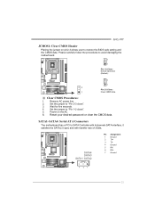
...to avoid damaging the motherboard. 3 1 Pin 1-2 Close: Normal Operation (Default). 3 1 3 Pin 2-3 Close: 1 Clear CMOS data. ※ Clear CMOS Procedures: 1. Please carefully follow the procedures to "Pin 1-2 close ". 3. Power on pin2-3 allows user to "Pin 2-3 close ". 5. Reset your desired password or clear the CMOS data. G41-M7 JCMOS1: Clear CMOS Header... 7 Ground 7 41 15 Set the jumper to restore the BIOS safe setting and the CMOS data. SATA1~SATA4: Serial ATA Connectors The motherboard has a PCI to SATA Controller with 4channels SATA interface, it satisfies the SATA...
...to avoid damaging the motherboard. 3 1 Pin 1-2 Close: Normal Operation (Default). 3 1 3 Pin 2-3 Close: 1 Clear CMOS data. ※ Clear CMOS Procedures: 1. Please carefully follow the procedures to "Pin 1-2 close ". 3. Power on pin2-3 allows user to "Pin 2-3 close ". 5. Reset your desired password or clear the CMOS data. G41-M7 JCMOS1: Clear CMOS Header... 7 Ground 7 41 15 Set the jumper to restore the BIOS safe setting and the CMOS data. SATA1~SATA4: Serial ATA Connectors The motherboard has a PCI to SATA Controller with 4channels SATA interface, it satisfies the SATA...


