Setup Manual
Page 2
... 12 3.2 Detail Settings 12 Chapter 4: Useful Help 18 4.1 Driver Installation Note 18 4.2 Software 19 4.3 Extra Information 24 4.4 AMI BIOS Beep Code 26 4.5 Troubleshooting 27 Appendix: SPEC In Other Language 28 German...28 France ...30 Italian...32 Spanish ...34 Portuguese ...36 Polish...38 Russian ...40 Arabic...42 Japanese ...44
... 12 3.2 Detail Settings 12 Chapter 4: Useful Help 18 4.1 Driver Installation Note 18 4.2 Software 19 4.3 Extra Information 24 4.4 AMI BIOS Beep Code 26 4.5 Troubleshooting 27 Appendix: SPEC In Other Language 28 German...28 France ...30 Italian...32 Spanish ...34 Portuguese ...36 Polish...38 Russian ...40 Arabic...42 Japanese ...44
Setup Manual
Page 4
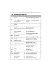
... Printer Port Connector x1 Each connector supports 1 Printer port Serial port Connector x1 Connects to 3.0 Gb/s. Motherboard Manual 1.3 MOTHERBOARD FEATURES SPEC LGA 775 Supports Hyper-Threading / Execute Disable Bit / Intel Core2Duo / Core2Quad / Enhanced Intel SpeedStep® / Intel Architecture-64 .../ Virtualization Celeron 4xx processor Technology FSB Support 800 / 1066 / 1333 / 1600 MHz Chipset Intel G31 Intel ICH7 ITE 8712F Environment Control initiatives, Super I/O Provides the most commonly used legacy Hardware Monitor Controller Super I/O functionality.
... Printer Port Connector x1 Each connector supports 1 Printer port Serial port Connector x1 Connects to 3.0 Gb/s. Motherboard Manual 1.3 MOTHERBOARD FEATURES SPEC LGA 775 Supports Hyper-Threading / Execute Disable Bit / Intel Core2Duo / Core2Quad / Enhanced Intel SpeedStep® / Intel Architecture-64 .../ Virtualization Celeron 4xx processor Technology FSB Support 800 / 1066 / 1333 / 1600 MHz Chipset Intel G31 Intel ICH7 ITE 8712F Environment Control initiatives, Super I/O Provides the most commonly used legacy Hardware Monitor Controller Super I/O functionality.
Setup Manual
Page 5
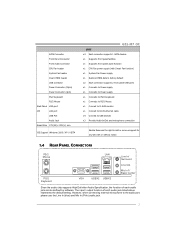
.../2 Keyboard PS/2 Mouse Back Panel VGA port I/O LAN port USB Port Audio Jack Board Size 179 (W) x 235 (L) mm OS Support Windows 2000 / XP / VISTA G31-M7 OC SPEC x4 Each connector supports 1 SATA devices x1 Supports front panel facilities x1 Supports front panel audio function x1 CPU Fan power supply (with Smart Fan... x1 Connect to D-SUB monitor x1 Connect to RJ-45 ethernet cable x4 Connect to USB devices x3 Provide Audio-In/Out and microphone connection Biostar Reserves the right to the audio port, please use the Line In (blue) and Mic In (Pink) audio jack. 3
.../2 Keyboard PS/2 Mouse Back Panel VGA port I/O LAN port USB Port Audio Jack Board Size 179 (W) x 235 (L) mm OS Support Windows 2000 / XP / VISTA G31-M7 OC SPEC x4 Each connector supports 1 SATA devices x1 Supports front panel facilities x1 Supports front panel audio function x1 CPU Fan power supply (with Smart Fan... x1 Connect to D-SUB monitor x1 Connect to RJ-45 ethernet cable x4 Connect to USB devices x3 Provide Audio-In/Out and microphone connection Biostar Reserves the right to the audio port, please use the Line In (blue) and Mic In (Pink) audio jack. 3

Setup Manual
Page 17
... the jumper to "Pin 2-3 close ". 5. Wait for five seconds. 4. Reset your desired password or clear the CMOS data. Power on pin2-3, it satisfies the SATA 2.0 spec and with 4channels SATA interface, it allows user to restore the BIOS safe setting and the CMOS data, please carefully follow the procedures to "Pin... the jumper to avoid damaging the motherboard. 3 1 Pin 1-2 Close: Normal Operation (Default). 3 1 3 1 Pin 2-3 Close: Clear CMOS data. ※ Clear CMOS Procedures: 1. Remove AC power line. 2. G31-M7 OC JCMOS1: Clear CMOS Header By placing the jumper on the AC. 6.
... the jumper to "Pin 2-3 close ". 5. Wait for five seconds. 4. Reset your desired password or clear the CMOS data. Power on pin2-3, it satisfies the SATA 2.0 spec and with 4channels SATA interface, it allows user to restore the BIOS safe setting and the CMOS data, please carefully follow the procedures to "Pin... the jumper to avoid damaging the motherboard. 3 1 Pin 1-2 Close: Normal Operation (Default). 3 1 3 1 Pin 2-3 Close: Clear CMOS data. ※ Clear CMOS Procedures: 1. Remove AC power line. 2. G31-M7 OC JCMOS1: Clear CMOS Header By placing the jumper on the AC. 6.