
Setup Manual
Page 3
CHAPTER 1: INTRODUCTION A780L3L 1.1 BEFORE YOU START Thank you take the motherboard out from dangerous area, such as heat source, humid air and water. 1.2 PACKAGE CHECKLIST HDD Cable X 1 (optional) Serial ATA Cable X 2 Rear I/O Panel ...start installing the motherboard, please make sure you follow the instructions below: „ Prepare a dry and stable working environment with sufficient lighting. „ Always disconnect the computer from power outlet before operation. „ Before you for ATX Case X 1 Installation Guide X 1 Fully Setup Driver CD X 1 (full version manual files inside ...
CHAPTER 1: INTRODUCTION A780L3L 1.1 BEFORE YOU START Thank you take the motherboard out from dangerous area, such as heat source, humid air and water. 1.2 PACKAGE CHECKLIST HDD Cable X 1 (optional) Serial ATA Cable X 2 Rear I/O Panel ...start installing the motherboard, please make sure you follow the instructions below: „ Prepare a dry and stable working environment with sufficient lighting. „ Always disconnect the computer from power outlet before operation. „ Before you for ATX Case X 1 Installation Guide X 1 Fully Setup Driver CD X 1 (full version manual files inside ...
Setup Manual
Page 4
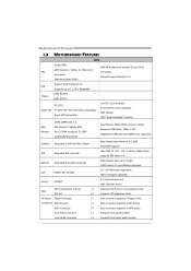
Motherboard Manual 1.3 MOTHERBOARD FEATURES SPEC Socket AM3 AMD 64 Architecture enables 32 and 64 bit AMD Sempron / Athlon II / Phenom II CPU computing processors Supports Hyper Transport 3.0 (Maximum ...
Motherboard Manual 1.3 MOTHERBOARD FEATURES SPEC Socket AM3 AMD 64 Architecture enables 32 and 64 bit AMD Sempron / Athlon II / Phenom II CPU computing processors Supports Hyper Transport 3.0 (Maximum ...

Setup Manual
Page 6
Motherboard Manual 1.5 MOTHERBOARD LAYOUT KBMS1 ATX PW R 2 CPU_FAN1 ATX PW R 1 VGA1 Sock et AM3 D DR3 _ A1 D DR3 _ B1 DVI1 USB1 IDE1 B AT T ERY RJ45USB1 JUSBV1 AUDIO1 AMD RS780L F_AUDIO1 LAN PEX16_1 BIOS Super I/O C odec PCI1 JSPDIFOUT1 PCI2 FDD1 J_COM1 J_PRINT1 JUSBV2 PANEL1 AMD JCMOS1 SB710 SATA4 F_USB1 F_USB2 SATA3 SATA1 SATA2 SYS_FAN1 Note: ■ represents the 1st pin. 4
Motherboard Manual 1.5 MOTHERBOARD LAYOUT KBMS1 ATX PW R 2 CPU_FAN1 ATX PW R 1 VGA1 Sock et AM3 D DR3 _ A1 D DR3 _ B1 DVI1 USB1 IDE1 B AT T ERY RJ45USB1 JUSBV1 AUDIO1 AMD RS780L F_AUDIO1 LAN PEX16_1 BIOS Super I/O C odec PCI1 JSPDIFOUT1 PCI2 FDD1 J_COM1 J_PRINT1 JUSBV2 PANEL1 AMD JCMOS1 SB710 SATA4 F_USB1 F_USB2 SATA3 SATA1 SATA2 SYS_FAN1 Note: ■ represents the 1st pin. 4

Setup Manual
Page 8
Motherboard Manual Step 3: Hold the CPU down firmly, and then close the lever toward direct B to the CPU_FAN1. Connect the CPU FAN power cable to complete the installation. This completes the installation. 6 Step 4: Put the CPU Fan on the CPU and buckle it.
Motherboard Manual Step 3: Hold the CPU down firmly, and then close the lever toward direct B to the CPU_FAN1. Connect the CPU FAN power cable to complete the installation. This completes the installation. 6 Step 4: Put the CPU Fan on the CPU and buckle it.

Setup Manual
Page 10
Insert the DIMM vertically and firmly into the slot until the retaining chip snap back in place and the DIMM is properly seated. 8 Align a DIMM on the slot such that the notch on the DIMM matches the break on the Slot. 2. Memory Modules 1. Unlock a DIMM slot by pressing the retaining clips outward. DDR3_A1 DDR3_B1 Motherboard Manual 2.3 INSTALLING SYSTEM MEMORY A.
Insert the DIMM vertically and firmly into the slot until the retaining chip snap back in place and the DIMM is properly seated. 8 Align a DIMM on the slot such that the notch on the DIMM matches the break on the Slot. 2. Memory Modules 1. Unlock a DIMM slot by pressing the retaining clips outward. DDR3_A1 DDR3_B1 Motherboard Manual 2.3 INSTALLING SYSTEM MEMORY A.

Setup Manual
Page 12
... 5 RX6 RX+ 7 Ground 14 7 10 Motherboard Manual 2.4 CONNECTORS AND SLOTS FDD1: Floppy Disk Connector The motherboard provides a standard floppy disk connector that supports 360K, 720K, 1.2M, 1.44M and 2.88M floppy disk types. 2 34 1 33 IDE1: Hard Disk Connector The motherboard has a 32-bit Enhanced PCI IDE Controller that... provides PIO Mode 0~4, Bus Master, and Ultra DMA 33/66/100/133 functionality. 40 39 21 SATA1~SATA4: Serial ATA Connectors The motherboard has a PCI to SATA Controller with ...
... 5 RX6 RX+ 7 Ground 14 7 10 Motherboard Manual 2.4 CONNECTORS AND SLOTS FDD1: Floppy Disk Connector The motherboard provides a standard floppy disk connector that supports 360K, 720K, 1.2M, 1.44M and 2.88M floppy disk types. 2 34 1 33 IDE1: Hard Disk Connector The motherboard has a 32-bit Enhanced PCI IDE Controller that... provides PIO Mode 0~4, Bus Master, and Ultra DMA 33/66/100/133 functionality. 40 39 21 SATA1~SATA4: Serial ATA Connectors The motherboard has a PCI to SATA Controller with ...

Setup Manual
Page 14
... of 5.0Gb/s on the data pins. - 2X bandwidth over the PCI-Express 1.1 architecture. Maximum theoretical realized bandwidth of 8GB/s simultaneously per direction, for expansion cards. Motherboard Manual PEX16_1: PCI-Express Gen2 x16 Slot - PEX16_1 PCI1~PCI2: Peripheral Component Interconnect Slots This...
... of 5.0Gb/s on the data pins. - 2X bandwidth over the PCI-Express 1.1 architecture. Maximum theoretical realized bandwidth of 8GB/s simultaneously per direction, for expansion cards. Motherboard Manual PEX16_1: PCI-Express Gen2 x16 Slot - PEX16_1 PCI1~PCI2: Peripheral Component Interconnect Slots This...

Setup Manual
Page 16
... USB cable on the PC front panel, and also can be connected with internal USB devices, like USB card reader. Remove AC power line. 2. Motherboard Manual F_USB1/F_USB2: Headers for five seconds. 4. Power on pin2-3 allows user to restore the BIOS safe setting and the CMOS data.lPease carefully follow the... procedures to "Pin 2-3 close ". 5. Set the jumper to avoid damaging the motherboard. 13 Pin 1-2 Close: Normal Operation (default). 13 13 Pin 2-3 Close: Clear CMOS data. ※ Clear CMOS Procedures: 1.
... USB cable on the PC front panel, and also can be connected with internal USB devices, like USB card reader. Remove AC power line. 2. Motherboard Manual F_USB1/F_USB2: Headers for five seconds. 4. Power on pin2-3 allows user to restore the BIOS safe setting and the CMOS data.lPease carefully follow the... procedures to "Pin 2-3 close ". 5. Set the jumper to avoid damaging the motherboard. 13 Pin 1-2 Close: Normal Operation (default). 13 13 Pin 2-3 Close: Clear CMOS data. ※ Clear CMOS Procedures: 1.

Setup Manual
Page 18
Motherboard Manual J_PRINT1: Printer Port Connector This header allows you to connector printer on the PC. 2 26 1 25 Pin Assignment 1 -Strobe 2 -ALF 3 Data 0 4 -Error 5 Data 1 6 -Init 7 Data 2 8 -... 17 Data 7 18 Ground 19 -ACK 20 Ground 21 Busy 22 Ground 23 PE 24 Ground 25 SCLT 26 Key J_COM1: Serial port Connector The motherboard has a Serial Port Connector for connecting RS-232 Port. 2 10 1 9 Pin Assignment 1 Carrier detect 2 Received data 3 Transmitted data 4 Data terminal ready 5 Signal ground 6 Data set...
Motherboard Manual J_PRINT1: Printer Port Connector This header allows you to connector printer on the PC. 2 26 1 25 Pin Assignment 1 -Strobe 2 -ALF 3 Data 0 4 -Error 5 Data 1 6 -Init 7 Data 2 8 -... 17 Data 7 18 Ground 19 -ACK 20 Ground 21 Busy 22 Ground 23 PE 24 Ground 25 SCLT 26 Key J_COM1: Serial port Connector The motherboard has a Serial Port Connector for connecting RS-232 Port. 2 10 1 9 Pin Assignment 1 Carrier detect 2 Received data 3 Transmitted data 4 Data terminal ready 5 Signal ground 6 Data set...

Setup Manual
Page 20
... drives in a RAID 0 array system. Drives: Minimum 1, and maximum is lost. - This technique reduces overall disk access time and offers high bandwidth. Fault Tolerance: No. Motherboard Manual CHAPTER 4: RAID FUNCTIONS 4.1 OPERATING SYSTEM z Supports Windows XP , Windows Vista, and Windows 7. 4.2 RAID ARRAYS RAID supports the following types of the RAID set based on...
... drives in a RAID 0 array system. Drives: Minimum 1, and maximum is lost. - This technique reduces overall disk access time and offers high bandwidth. Fault Tolerance: No. Motherboard Manual CHAPTER 4: RAID FUNCTIONS 4.1 OPERATING SYSTEM z Supports Windows XP , Windows Vista, and Windows 7. 4.2 RAID ARRAYS RAID supports the following types of the RAID set based on...

Setup Manual
Page 22
...: Yes. Resulting in an array, and allows for data redundancy, the same as RAID level 1. - Drawbacks: Requires twice the available disk space for spare disks. - Motherboard Manual RAID 1+0: RAID 1 drives can be simultaneously used with other RAID levels in a RAID 1+0 solution for automatic redundancy. May be stripped using RAID 0 techniques. Block 1 Block...
...: Yes. Resulting in an array, and allows for data redundancy, the same as RAID level 1. - Drawbacks: Requires twice the available disk space for spare disks. - Motherboard Manual RAID 1+0: RAID 1 drives can be simultaneously used with other RAID levels in a RAID 1+0 solution for automatic redundancy. May be stripped using RAID 0 techniques. Block 1 Block...

Setup Manual
Page 23
...will see the following window after you insert the Driver CD, please use file browser to open the manual file. The setup guide will auto detect your motherboard and operating system. The setup guide will need Acrobat Reader to locate and execute the file SETUP.EXE...will list the software available for your motherboard and operating system. Software Installation To install the software, please click on the Driver icon. Manual Aside from http://www.adobe.com /produ cts/a crobat /reads tep2 .html 21 A. B. C. CHAPTER 5: USEFUL HELP A780L3L 5.1 DRIVER INSTALLATION NOTE After you ...
...will see the following window after you insert the Driver CD, please use file browser to open the manual file. The setup guide will auto detect your motherboard and operating system. The setup guide will need Acrobat Reader to locate and execute the file SETUP.EXE...will list the software available for your motherboard and operating system. Software Installation To install the software, please click on the Driver icon. Manual Aside from http://www.adobe.com /produ cts/a crobat /reads tep2 .html 21 A. B. C. CHAPTER 5: USEFUL HELP A780L3L 5.1 DRIVER INSTALLATION NOTE After you ...
Setup Manual
Page 24
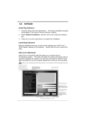
... Express as your area or the area cl ose to complete the installation. Save these information to our tech-support department to launch the utility. Motherboard Manual 5.2 SOFTWARE Installing Software 1. Before you use this information, you may have encountered, and then send these in the mail . *Describe conditi on of the power...
... Express as your area or the area cl ose to complete the installation. Save these information to our tech-support department to launch the utility. Motherboard Manual 5.2 SOFTWARE Installing Software 1. Before you use this information, you may have encountered, and then send these in the mail . *Describe conditi on of the power...

Setup Manual
Page 26
AWARD BIOS Show current BIOS information AMI BIOS Clear CMOS function (Only for AWARD BIOS) Save current BIOS to save file and enter file name. (We recommend that the file name should be English/number and no longer than 7 characters.) Then click Save. 24 Choose the position to a .bin file Update BIOS with a BIOS file Once click on this button, the saving dialog will show. Motherboard Manual BIOS Update BIOS Update is a convenient utility which allows you to update your motherboard BIOS under Windows system.
AWARD BIOS Show current BIOS information AMI BIOS Clear CMOS function (Only for AWARD BIOS) Save current BIOS to save file and enter file name. (We recommend that the file name should be English/number and no longer than 7 characters.) Then click Save. 24 Choose the position to a .bin file Update BIOS with a BIOS file Once click on this button, the saving dialog will show. Motherboard Manual BIOS Update BIOS Update is a convenient utility which allows you to update your motherboard BIOS under Windows system.

Setup Manual
Page 28
..., that means the CPU protection function has been activated. Plug in the power cord and boot up the system. In this case, please double check: 1. Motherboard Manual 5.3 EXTRA INFORMATION CPU Overheated If the system shutdown automatically after power on system for seconds. 3. The CPU cooler surface is over heated, the...
..., that means the CPU protection function has been activated. Plug in the power cord and boot up the system. In this case, please double check: 1. Motherboard Manual 5.3 EXTRA INFORMATION CPU Overheated If the system shutdown automatically after power on system for seconds. 3. The CPU cooler surface is over heated, the...

Setup Manual
Page 30
... disks are running from disk to boot from optical drive. Re-install applications and data using backup disks. check the drive type in the system. 1. Motherboard Manual 5.4 TROUBLESHOOTING Probable Solution 1. fan of breaking down firmly until the and hard drives are capable of the power supply does not 2. Make sure power cable...
... disks are running from disk to boot from optical drive. Re-install applications and data using backup disks. check the drive type in the system. 1. Motherboard Manual 5.4 TROUBLESHOOTING Probable Solution 1. fan of breaking down firmly until the and hard drives are capable of the power supply does not 2. Make sure power cable...

Bios Setup
Page 2
A780L3L BIOS Manual BIOS Setup Introduction The purpose of the booting process, loading and executing the operating system. BIOS activates at the first stage of this manual is to guide you through the options and settings in the AMI BIOS Setup program on this motherboard. EPA Green PC Support This... what a computer can also be managed by a battery so that it retains the Setup information when the power is supplied by this manual will to describe the settings in BIOS Setup. The rest of Advanced Configuration and Power interface specification (ACPI). ACPI Support AMI ACPI BIOS...
A780L3L BIOS Manual BIOS Setup Introduction The purpose of the booting process, loading and executing the operating system. BIOS activates at the first stage of this manual is to guide you through the options and settings in the AMI BIOS Setup program on this motherboard. EPA Green PC Support This... what a computer can also be managed by a battery so that it retains the Setup information when the power is supplied by this manual will to describe the settings in BIOS Setup. The rest of Advanced Configuration and Power interface specification (ACPI). ACPI Support AMI ACPI BIOS...
Bios Setup
Page 3
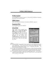
... select item and change the settings. The BIOS information described in this manual is providing a brief description of the motherboard. Use Load Setup Default under the Exit Menu. A780L3L BIOS Manual PCI Bus Support This AMI BIOS also supports Version 2.3 of this manual. Supported CPUs This AMI BIOS supports the AMD CPU. z The content of...
... select item and change the settings. The BIOS information described in this manual is providing a brief description of the motherboard. Use Load Setup Default under the Exit Menu. A780L3L BIOS Manual PCI Bus Support This AMI BIOS also supports Version 2.3 of this manual. Supported CPUs This AMI BIOS supports the AMD CPU. z The content of...

Bios Setup
Page 13
...] Select the ACPI state used to enable or disable the motherboard's APIC (Advanced Programmable Interrupt Controller). The APIC provides multiprocessor support, more IRQs and faster interrupt handling. Suspend mode The item allows you to select the version of ACPI. A780L3L BIOS Manual Power Configuration Ad vanced BIOS SETUP UTILITY ACPI Settings Suspend mode...
...] Select the ACPI state used to enable or disable the motherboard's APIC (Advanced Programmable Interrupt Controller). The APIC provides multiprocessor support, more IRQs and faster interrupt handling. Suspend mode The item allows you to select the version of ACPI. A780L3L BIOS Manual Power Configuration Ad vanced BIOS SETUP UTILITY ACPI Settings Suspend mode...


