Owners Manual
Page 3
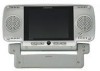
...service personnel if your system is plug and play. When cleaning, make sure the system is constructed to provide years of heat. DIN Cable 112-3092 One 3. AC to strong magnetic fields. Pouch 126-1170 One 2 Cautions 1. Do not use liquid cleaners or ...the VBPEX5, 5 inch Liquid Crystal Display (LCD ) Monitor. Contents ITEM PART NUMBER QUANTITY 1. 5" LCD Monitor VPBEX5 136C2124 One 2. The Monitor utilizes the latest state of the unit. Please read the entire manual prior to the VBP3000 and VBP4000, (Please contact Audiovox's retailers). Keep the unit away from the ...
...service personnel if your system is plug and play. When cleaning, make sure the system is constructed to provide years of heat. DIN Cable 112-3092 One 3. AC to strong magnetic fields. Pouch 126-1170 One 2 Cautions 1. Do not use liquid cleaners or ...the VBPEX5, 5 inch Liquid Crystal Display (LCD ) Monitor. Contents ITEM PART NUMBER QUANTITY 1. 5" LCD Monitor VPBEX5 136C2124 One 2. The Monitor utilizes the latest state of the unit. Please read the entire manual prior to the VBP3000 and VBP4000, (Please contact Audiovox's retailers). Keep the unit away from the ...

Owners Manual
Page 6
...AC/DC adapter into the cigarette lighter socket. This can be done with the Monitor inside or outside the pouch. 3 5 3 F. Powering the Unit NOTE: When the VBPEX5 is connected to either a VBP3000 or VBP4000 using the supplied DIN cable, there is no need for a power source to be connected to Figure ...5) Figure 5 Using the cigarette lighter adapter supplied, plug the connector end into the DC 12V IN jack on the side of the Monitor.
...AC/DC adapter into the cigarette lighter socket. This can be done with the Monitor inside or outside the pouch. 3 5 3 F. Powering the Unit NOTE: When the VBPEX5 is connected to either a VBP3000 or VBP4000 using the supplied DIN cable, there is no need for a power source to be connected to Figure ...5) Figure 5 Using the cigarette lighter adapter supplied, plug the connector end into the DC 12V IN jack on the side of the Monitor.
Owners Manual
Page 7
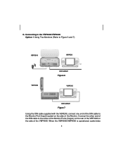
Connect the other end of the DIN cable to the Monitor Port (Input) located on the rear of the VBP3000 or the side of the Monitor. Connecting to the VBP3000/VBP4000 Option 1 Using Two Monitors (Refer to Figure 6 and 7) VBP3000 VBP4000 VBPEX5 DIN CABLE Figure 6 VBVPBEPXE5X5 DIN CABLE Figure 7 Using the DIN cable supplied with the VBPEX5, connect one end of the DIN cable to the either of the Monitor Ports (Output) on the side of the VBP4000. G. When the VBP3000/VBP4000 is operational, audio/video 6 6
Connect the other end of the DIN cable to the Monitor Port (Input) located on the rear of the VBP3000 or the side of the Monitor. Connecting to the VBP3000/VBP4000 Option 1 Using Two Monitors (Refer to Figure 6 and 7) VBP3000 VBP4000 VBPEX5 DIN CABLE Figure 6 VBVPBEPXE5X5 DIN CABLE Figure 7 Using the DIN cable supplied with the VBPEX5, connect one end of the DIN cable to the either of the Monitor Ports (Output) on the side of the VBP4000. G. When the VBP3000/VBP4000 is operational, audio/video 6 6
Owners Manual
Page 8
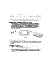
... Volt DC ) and Infrared control signals are routed through the DIN cable to Figure 4 and Figure 5. Using External Audio/Video Sources (Refer to Figure 8) Connect the VBPEX5 to turn the Monitor on position to an external power source. H. Figure 8 I. NOTE: If connecting the Monitor to the VBP4000 be turned off. Plug the video output...
... Volt DC ) and Infrared control signals are routed through the DIN cable to Figure 4 and Figure 5. Using External Audio/Video Sources (Refer to Figure 8) Connect the VBPEX5 to turn the Monitor on position to an external power source. H. Figure 8 I. NOTE: If connecting the Monitor to the VBP4000 be turned off. Plug the video output...

