Owners Manual
Page 4
...14 For better reception 10 Connecting your TV 10-11 Connecting a VCR 12 Connecting another source 12 Connecting the speakers & subwoofer 13 Positioning the speakers and subwoofer 13 Mounting rear surround speakers 14 Turning on the Unit and TV 14 Power cord connection 14 Adjusting the Sound 15-16 Playing a Disc... setting 27 VIDEO setting 27-29 TV Shape 27 Video Output 28 Brightness 29 Edges 29 AUDIO setting 30-32 Digital Out 30 L/R speaker 30 Subwoofer 31 Surround Delay 31 Center Delay 32 Pink noise 32 RATING setting 33-34 Password/Parental lock 33 Factory Set 34 Radio ...
...14 For better reception 10 Connecting your TV 10-11 Connecting a VCR 12 Connecting another source 12 Connecting the speakers & subwoofer 13 Positioning the speakers and subwoofer 13 Mounting rear surround speakers 14 Turning on the Unit and TV 14 Power cord connection 14 Adjusting the Sound 15-16 Playing a Disc... setting 27 VIDEO setting 27-29 TV Shape 27 Video Output 28 Brightness 29 Edges 29 AUDIO setting 30-32 Digital Out 30 L/R speaker 30 Subwoofer 31 Surround Delay 31 Center Delay 32 Pink noise 32 RATING setting 33-34 Password/Parental lock 33 Factory Set 34 Radio ...

Owners Manual
Page 8
... 25) / CURSOR buttons Use to highlight selections on a menu screen and adjust certain settings. 26) 5.1 / 2.1 CH button Switch speaker output to 5.1 channel mode. (All speakers + subwoofer) 30 Switch speaker outputs to 2.1 channel. (Front left/right speakers + subwoofer) 31 27) SOUND button Selects sound balance and tone controls for mono sound. TV shows "PAL" or...
... 25) / CURSOR buttons Use to highlight selections on a menu screen and adjust certain settings. 26) 5.1 / 2.1 CH button Switch speaker output to 5.1 channel mode. (All speakers + subwoofer) 30 Switch speaker outputs to 2.1 channel. (Front left/right speakers + subwoofer) 31 27) SOUND button Selects sound balance and tone controls for mono sound. TV shows "PAL" or...

Owners Manual
Page 9
... button. Rear Panel 1112 13 1415 16 17 18 FM ANT. 300Ω 19 20 212223 24 25 26 11) Right FRONT speaker terminals 12) SUBWOOFER terminals 13) Left REAR speaker terminals 14) FM ANTENNA jack 15) DIGITAL AUDIO OUT jack 16) COMPONENT VIDEO jacks (Y, PB/CB, PR/CR) 17) VIDEO OUT... jack 18) Left/Right AUDIO IN jacks 19) Right REAR speaker terminals 20) CENTER speaker terminals 21) Left FRONT speaker terminals 22) AM(MW) LOOP ANTENNA terminal 23) S-VIDEO OUT jack 24) Left/Right AUDIO OUT jacks 25) VIDEO IN (VCR) jack...
... button. Rear Panel 1112 13 1415 16 17 18 FM ANT. 300Ω 19 20 212223 24 25 26 11) Right FRONT speaker terminals 12) SUBWOOFER terminals 13) Left REAR speaker terminals 14) FM ANTENNA jack 15) DIGITAL AUDIO OUT jack 16) COMPONENT VIDEO jacks (Y, PB/CB, PR/CR) 17) VIDEO OUT... jack 18) Left/Right AUDIO IN jacks 19) Right REAR speaker terminals 20) CENTER speaker terminals 21) Left FRONT speaker terminals 22) AM(MW) LOOP ANTENNA terminal 23) S-VIDEO OUT jack 24) Left/Right AUDIO OUT jacks 25) VIDEO IN (VCR) jack...

Owners Manual
Page 11
... of the Main Unit, you want the sound come from the Main Unit to the VIDEO IN and left /right AUDIO OUT jacks from the speakers of your TV. RCA Audio/Video cable Use the Audio/Video cable (supplied). Connect the VIDEO OUT and left/right AUDIO OUT jacks on the...
... of the Main Unit, you want the sound come from the Main Unit to the VIDEO IN and left /right AUDIO OUT jacks from the speakers of your TV. RCA Audio/Video cable Use the Audio/Video cable (supplied). Connect the VIDEO OUT and left/right AUDIO OUT jacks on the...

Owners Manual
Page 13
...Turn on your Unit to your another source Analogue connection Using the Audio cable (not supplied), connect the left and right Audio cable from the speakers will be copied. This is only for DVD. Using the Audio cable (not supplied), connect the left /right audio inputs on your VCR. ...videotape. Using the Video cable (not supplied), connect the VIDEO IN (VCR) jack on the Unit. 2. If you want the sound come from the speakers of the equipment from the wall outlet before making any connection. • If the external equipment is a television and this , connect the left/right ...
...Turn on your Unit to your another source Analogue connection Using the Audio cable (not supplied), connect the left and right Audio cable from the speakers will be copied. This is only for DVD. Using the Audio cable (not supplied), connect the left /right audio inputs on your VCR. ...videotape. Using the Video cable (not supplied), connect the VIDEO IN (VCR) jack on the Unit. 2. If you want the sound come from the speakers of the equipment from the wall outlet before making any connection. • If the external equipment is a television and this , connect the left/right ...

Owners Manual
Page 14
...corresponding jacks on the rear of the Unit, matching the color tube on the end of the speaker wire to next page) 4/24/2004, 12:24 PM Positioning the speakers and subwoofer FRONT SPEAKERS Place on the top of the TV, equal distances apart. CENTER Place on both sides of or... below the TV. Connecting the speakers & subwoofer The speaker cords have been color-coded to simplify connection. E-10-16.pmd 13 REAR SPEAKERS Place right beside or slightly behind your listening position, and a little higher than your ears. CENTER...
...corresponding jacks on the rear of the Unit, matching the color tube on the end of the speaker wire to next page) 4/24/2004, 12:24 PM Positioning the speakers and subwoofer FRONT SPEAKERS Place on the top of the TV, equal distances apart. CENTER Place on both sides of or... below the TV. Connecting the speakers & subwoofer The speaker cords have been color-coded to simplify connection. E-10-16.pmd 13 REAR SPEAKERS Place right beside or slightly behind your listening position, and a little higher than your ears. CENTER...
Owners Manual
Page 15
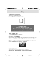
... the channel on while the unit is at the marked position on your TV corresponding to the VIDEO IN jack that all the components and speakers are connected correctly. • To prevent electrical shock, match wide blade of plug to wide slot, fully insert. • Be sure ... before making connections. • When you have connected the Unit successfully, the DVD logo (start-up picture) will be turned to . Setup Mounting rear surround speakers 1) Mark the correct mounting position on the wall. 2) Insert a fixing screw(s) at standby mode. Need More Help? E-10-16.pmd E - 14 14 4/...
... the channel on while the unit is at the marked position on your TV corresponding to the VIDEO IN jack that all the components and speakers are connected correctly. • To prevent electrical shock, match wide blade of plug to wide slot, fully insert. • Be sure ... before making connections. • When you have connected the Unit successfully, the DVD logo (start-up picture) will be turned to . Setup Mounting rear surround speakers 1) Mark the correct mounting position on the wall. 2) Insert a fixing screw(s) at standby mode. Need More Help? E-10-16.pmd E - 14 14 4/...

Owners Manual
Page 16
...the Movie mode. Dolby Pro Logic II creates five full-bandwidth output channels from the front left and right speakers. Movie mode is the standard required for autosound music systems (without adding any button within a few seconds, ... in effect Use the remote control to make the following changes to speaker balance: Front speaker (left) • Press the SOUND button repeatedly to display will show on the display of ...the Unit. Center speaker , then press the or CURSOR button toadjust the sound level. It • Press ...
...the Movie mode. Dolby Pro Logic II creates five full-bandwidth output channels from the front left and right speakers. Movie mode is the standard required for autosound music systems (without adding any button within a few seconds, ... in effect Use the remote control to make the following changes to speaker balance: Front speaker (left) • Press the SOUND button repeatedly to display will show on the display of ...the Unit. Center speaker , then press the or CURSOR button toadjust the sound level. It • Press ...

Owners Manual
Page 17
... 5.1 CH will not be activated on the front panel of display will be corresponded to the audio/sound output from Front Left and Front Right speakers plus the Subwoofer. • 5.1/2.1 CH button is no t applied o n Tuner, M P 3 and PCM DVD. 5.1 - The ultimate "cure" for poor FM stereo... code, and if the product maker would like to enhance mono signals by setup menu. The Matrix mode may be ". The following table shows which speakers are trademarks of Digital Theater Systems, Inc. ON ON OFF ON ON OFF --ON OFF ON OFF ON ON OFF --ON ON OFF EMU 5.1 5.1 5 2.1 2 2 5.1 2.1 2 5.1 5 2.1 2 2...
... 5.1 CH will not be activated on the front panel of display will be corresponded to the audio/sound output from Front Left and Front Right speakers plus the Subwoofer. • 5.1/2.1 CH button is no t applied o n Tuner, M P 3 and PCM DVD. 5.1 - The ultimate "cure" for poor FM stereo... code, and if the product maker would like to enhance mono signals by setup menu. The Matrix mode may be ". The following table shows which speakers are trademarks of Digital Theater Systems, Inc. ON ON OFF ON ON OFF --ON OFF ON OFF ON ON OFF --ON ON OFF EMU 5.1 5.1 5 2.1 2 2 5.1 2.1 2 5.1 5 2.1 2 2...
Owners Manual
Page 31
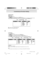
.... 4.To exit the FUNCTION SETUP MENU and return to the normal screen, press the RETURN button. L/R Speaker Small : Small size of Speaker (speaker diameter normally larger than 4 inch or 10 cm) Note : • You can adjust the channel balance.../2004, 10:32 AM E-27-34.pmd E - 30 30 (continued on your Unit. L/R Speaker 1.Press the SETUP button. 2.Use or button to select the Audio, press the ENTER button. 3.Use or button to... L/R Speaker, and then press the ENTER button. 4.Use or button to select the desired setting, and...
.... 4.To exit the FUNCTION SETUP MENU and return to the normal screen, press the RETURN button. L/R Speaker Small : Small size of Speaker (speaker diameter normally larger than 4 inch or 10 cm) Note : • You can adjust the channel balance.../2004, 10:32 AM E-27-34.pmd E - 30 30 (continued on your Unit. L/R Speaker 1.Press the SETUP button. 2.Use or button to select the Audio, press the ENTER button. 3.Use or button to... L/R Speaker, and then press the ENTER button. 4.Use or button to select the desired setting, and...

Owners Manual
Page 32
... FUNCTION SETUP MENU and return to the normal screen, press the RETURN button. Please see "ADJUSTING THE SOUND". If the location of your surround speakers and the front speakers. E-27-34.pmd E - 31 31 (continued on your subwoofer is selected, no sound will be emitted by subwoofer. Note : • You ... represents the Dolby Digital and the second number represents the Pro Logic. • The delay adjustment depends on the location of the surround speakers is closer than the front speakers, the delay adjustment can adjust the channel balance on next page) 4/26/2004, 10:32 AM
... FUNCTION SETUP MENU and return to the normal screen, press the RETURN button. Please see "ADJUSTING THE SOUND". If the location of your surround speakers and the front speakers. E-27-34.pmd E - 31 31 (continued on your subwoofer is selected, no sound will be emitted by subwoofer. Note : • You ... represents the Dolby Digital and the second number represents the Pro Logic. • The delay adjustment depends on the location of the surround speakers is closer than the front speakers, the delay adjustment can adjust the channel balance on next page) 4/26/2004, 10:32 AM

Owners Manual
Page 33
... RETURN button. Right : Pink noise comes out from subwoofer for testing. Please "Adjusting the Sound". E - 32 (continued on the location of your speakers. Pink noise Off : Pink noise test mode should always be switched off, unless you can press the SOUND button on the remote control to the... normal screen, press the RETURN button. Left : Pink noise comes out from rear surround left speaker for testing. Left sur : Pink noise comes out from front left speaker and the listener, this delay adjustment is less than the distance between the front right and left...
... RETURN button. Right : Pink noise comes out from subwoofer for testing. Please "Adjusting the Sound". E - 32 (continued on the location of your speakers. Pink noise Off : Pink noise test mode should always be switched off, unless you can press the SOUND button on the remote control to the... normal screen, press the RETURN button. Left : Pink noise comes out from rear surround left speaker for testing. Left sur : Pink noise comes out from front left speaker and the listener, this delay adjustment is less than the distance between the front right and left...

Owners Manual
Page 36
... but the signal reproduced will be preset. 1.Press the FUNCTION button until the frequency band appears on the display. 2. Note: • The left / right front speakers and subwoofer are activated only. Presetting stations You can tune into a stored station directly by entering the preset number. 20 stations on FM band can...
... but the signal reproduced will be preset. 1.Press the FUNCTION button until the frequency band appears on the display. 2. Note: • The left / right front speakers and subwoofer are activated only. Presetting stations You can tune into a stored station directly by entering the preset number. 20 stations on FM band can...

Owners Manual
Page 39
... The Unit and disc region number are connected securely. • Make sure that AUDIO output and AV IN input connections correct. • Adjust the speakers volume. • The DTS DVD disc cannot be decoded to turn off half 30 minutes for a few open. Wipe them with a cloth slightly moistened... with new ones. Press the ZOOM/TV MODE button on the remote to output the video signal. • Condensation may have speaker output. • This Unit is heard. • Check that the connecting cords are away from a transformer or motor, and at the remote sensor...
... The Unit and disc region number are connected securely. • Make sure that AUDIO output and AV IN input connections correct. • Adjust the speakers volume. • The DTS DVD disc cannot be decoded to turn off half 30 minutes for a few open. Wipe them with a cloth slightly moistened... with new ones. Press the ZOOM/TV MODE button on the remote to output the video signal. • Condensation may have speaker output. • This Unit is heard. • Check that the connecting cords are away from a transformer or motor, and at the remote sensor...