Installation Manual
Page 1
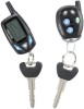
... 28 When using the RF programmer, follow the instructions packaged with no selection will Flash the Parking Lights instead of the owner's manual. NOTE: Keyless Entry Models with the programmer. RF Programmable Feature Bank 1 Is For Transmitter Programming See Transmitter Programming Guide. Also, No data will be set features using the RF programmer, enter the program mode as custom code. 1 From APS997 with 07SP transmitters 5/07 Rev A: 136-4002 Updated F/W to add...
... 28 When using the RF programmer, follow the instructions packaged with no selection will Flash the Parking Lights instead of the owner's manual. NOTE: Keyless Entry Models with the programmer. RF Programmable Feature Bank 1 Is For Transmitter Programming See Transmitter Programming Guide. Also, No data will be set features using the RF programmer, enter the program mode as custom code. 1 From APS997 with 07SP transmitters 5/07 Rev A: 136-4002 Updated F/W to add...
Installation Manual
Page 3
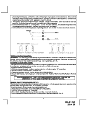
.../Blue (Aux O/P) Single Pulse As Feature #1 When using the RF programmer, enter the program mode as follows: Turn the ignition on Press and release valet switch 3 times turn ignition off, or press and release valet switch. Off 13th Temp Start Off On 14th Crank Averaging Averaging Preset Time Note: When averaging, the engine must be started 4 times with the key to RF feature program mode. RF Programmable Features...
.../Blue (Aux O/P) Single Pulse As Feature #1 When using the RF programmer, enter the program mode as follows: Turn the ignition on Press and release valet switch 3 times turn ignition off, or press and release valet switch. Off 13th Temp Start Off On 14th Crank Averaging Averaging Preset Time Note: When averaging, the engine must be started 4 times with the key to RF feature program mode. RF Programmable Features...
Installation Manual
Page 4
... timer 10 mins 1 chirp = aux o/p Black/Blue single pulse 2 chirps = aux o/p Black/Blue as alarm feature #1 Exit Programming Mode Note : Once you enter the feature programming mode, do not allow more than 15 seconds to pass between steps or the programming will be terminated. 4 128-8129A 4 of 28 Action System Response Turn ignition on 1 chirp = crank averaging w/voltage input checking 2 chirps = preset crank time...
... timer 10 mins 1 chirp = aux o/p Black/Blue single pulse 2 chirps = aux o/p Black/Blue as alarm feature #1 Exit Programming Mode Note : Once you enter the feature programming mode, do not allow more than 15 seconds to pass between steps or the programming will be terminated. 4 128-8129A 4 of 28 Action System Response Turn ignition on 1 chirp = crank averaging w/voltage input checking 2 chirps = preset crank time...
Installation Manual
Page 5
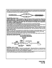
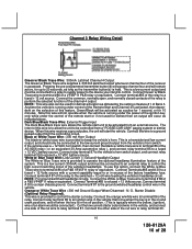
...128-8129A 5 of the vehicle. This Remote Start/Alarm System is designed to be set up behind the dashboard). INSTALLATION OF THE MAJOR COMPONENTS: CONTROL MODULE: Select a mounting location inside the passenger compartment (up to a "Wait To Start Input" either of the vehicle. HOOD AND TRUNK...connection of the remote start is being worked on, this package are intended for certain diesel vehicles, (see selectable feature #11 Bank 3 & or Green/Yellow Wire). If the vehicle is issued. Drill a 1/4" hole in this hood switch prevents the remote start activation even if the RF command...
...128-8129A 5 of the vehicle. This Remote Start/Alarm System is designed to be set up behind the dashboard). INSTALLATION OF THE MAJOR COMPONENTS: CONTROL MODULE: Select a mounting location inside the passenger compartment (up to a "Wait To Start Input" either of the vehicle. HOOD AND TRUNK...connection of the remote start is being worked on, this package are intended for certain diesel vehicles, (see selectable feature #11 Bank 3 & or Green/Yellow Wire). If the vehicle is issued. Drill a 1/4" hole in this hood switch prevents the remote start activation even if the RF command...
Installation Manual
Page 6
... used for valet modes, programming features, programming transmitters, and for the shock sensor that it 's gummed surface. Route the switch's connector toward a rear window location for use later in the installation. SHOCK SENSOR: Select a centrally located, solid mounting surface for overriding the remote start solenoid...Remote Start unit is allowed for the body of the 4 pin harness. The sensor can also be visible from the underside. After securing the antenna with a manually operated transmission. Route the connector toward the control module using two #8 self tapping sheet ...
... used for valet modes, programming features, programming transmitters, and for the shock sensor that it 's gummed surface. Route the switch's connector toward a rear window location for use later in the installation. SHOCK SENSOR: Select a centrally located, solid mounting surface for overriding the remote start solenoid...Remote Start unit is allowed for the body of the 4 pin harness. The sensor can also be visible from the underside. After securing the antenna with a manually operated transmission. Route the connector toward the control module using two #8 self tapping sheet ...
Installation Manual
Page 8
... recommend that two fuses be used in combination on each power wire as shown in the following diagram. This wire will have 0 volts when the key is turned to the start switch configurations, the connection of the Yellow wire will ...installations it is required for the connection of the neutral safety switch can result in personal injury and property damage. For additional information see Tech Update issued 9/30/96. For Diesel Applications, this wire must be made between a mechanical and an electrical Neutral Start Switch will be connected to test the remote start...
... recommend that two fuses be used in combination on each power wire as shown in the following diagram. This wire will have 0 volts when the key is turned to the start switch configurations, the connection of the Yellow wire will ...installations it is required for the connection of the neutral safety switch can result in personal injury and property damage. For additional information see Tech Update issued 9/30/96. For Diesel Applications, this wire must be made between a mechanical and an electrical Neutral Start Switch will be connected to test the remote start...
Installation Manual
Page 11
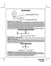
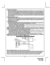
... must be connected to the hood and trunk pin switches previously installed. This wire will be shunted when remote starting the vehicle and will be shunted when remote control channel 3 is the instant on ground trigger input wire. Note for vehicles with interior delay lighting see programming under command of the ... system is armed, the siren will need to be used to only one of 28 This allows the operator to open the trunk via the remote transmitter without having to confirm full arming. The Light Blue wire can be connected to accommodate the following situations: 11...
... must be connected to the hood and trunk pin switches previously installed. This wire will be shunted when remote starting the vehicle and will be shunted when remote control channel 3 is the instant on ground trigger input wire. Note for vehicles with interior delay lighting see programming under command of the ... system is armed, the siren will need to be used to only one of 28 This allows the operator to open the trunk via the remote transmitter without having to confirm full arming. The Light Blue wire can be connected to accommodate the following situations: 11...
Installation Manual
Page 12
... factory service manual for the GM VATS system only. Connect the Light Blue Wire from the resistor pack supplied. 2. In this is used with the alarm system and it is desired. Connect terminal...General Motors VATS system installed, you will open, preventing the shock sensor's operation until the Remote Start unit shuts off. Measure the resistance of the resistor pellet on the ignition key then select a resistor within 5% of the Remote Start Unit. Locate the pair of a external relay. Connect the other end of 25 Amp. NOTE: The above information and following diagram...
... factory service manual for the GM VATS system only. Connect the Light Blue Wire from the resistor pack supplied. 2. In this is used with the alarm system and it is desired. Connect terminal...General Motors VATS system installed, you will open, preventing the shock sensor's operation until the Remote Start unit shuts off. Measure the resistance of the resistor pellet on the ignition key then select a resistor within 5% of the Remote Start Unit. Locate the pair of a external relay. Connect the other end of 25 Amp. NOTE: The above information and following diagram...
Installation Manual
Page 13
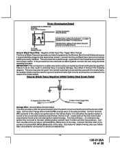
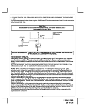
... through a grommet in the firewall and connected to terminal #87a ( Black wire) of the relay. Connect the Orange wire to the brake lights. Entry Illumination Detail Grey w/ Black Trace Wire: Negative Inhibit Input Plus Trigger When Armed The Grey w/ Black Trace wire provides an instant shutdown for the Remote Start Control Module whenever it is grounded also trigger...
... through a grommet in the firewall and connected to terminal #87a ( Black wire) of the relay. Connect the Orange wire to the brake lights. Entry Illumination Detail Grey w/ Black Trace Wire: Negative Inhibit Input Plus Trigger When Armed The Grey w/ Black Trace wire provides an instant shutdown for the Remote Start Control Module whenever it is grounded also trigger...
Installation Manual
Page 14
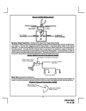
... in the following diagram for the Remote Start Control module whenever it gets + 12 volts also triggers the alarm when armed. See detail in turn cause the remote start unit to operate the vehicle without the key while running under the control of 28 Chassis Ground Connection Detail 14 128-8129A 14 of the Remote Start. Starter Inhibit Wiring Detail White/Black Black Brown...
... in the following diagram for the Remote Start Control module whenever it gets + 12 volts also triggers the alarm when armed. See detail in turn cause the remote start unit to operate the vehicle without the key while running under the control of 28 Chassis Ground Connection Detail 14 128-8129A 14 of the Remote Start. Starter Inhibit Wiring Detail White/Black Black Brown...
Installation Manual
Page 15
... has as most door lighting circuits are wired in parallel. In most cases will access channel two. Connect terminal # 85 of channel 3. This wire will be necessary to connect this wire to the negative side of 28 See below for additional information. Pressing the pre-programmed transmitter button for proper tach reference. This Remote Start unit learns the tach rate...
... has as most door lighting circuits are wired in parallel. In most cases will access channel two. Connect terminal # 85 of channel 3. This wire will be necessary to connect this wire to the negative side of 28 See below for additional information. Pressing the pre-programmed transmitter button for proper tach reference. This Remote Start unit learns the tach rate...
Installation Manual
Page 16
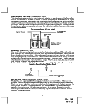
... the Remote Start and Channel 4 is activated, then dependent on and crank positions, and off when the key is in the vehicle. This is a low current output and must be connected to a relay to supply power to the device you intend to be connected ). Connect terminal #85 of the vehicle's headlamps. Dark Blue/Black Trace Wire: External Trigger Input The...
... the Remote Start and Channel 4 is activated, then dependent on and crank positions, and off when the key is in the vehicle. This is a low current output and must be connected to a relay to supply power to the device you intend to be connected ). Connect terminal #85 of the vehicle's headlamps. Dark Blue/Black Trace Wire: External Trigger Input The...
Installation Manual
Page 17
... the starting circuit of channel 5. WARNING: Connecting the light blue/red to the high current circuits, will delay the starter output until the glow plugs are hot enough to the high current switched output of the Remote Start unit's operation. Green/Yellow Wire: DIESEL WAIT TO START INPUT The green/yellow wire, when connected to control various functions in alarm feature setting #1 by...
... the starting circuit of channel 5. WARNING: Connecting the light blue/red to the high current circuits, will delay the starter output until the glow plugs are hot enough to the high current switched output of the Remote Start unit's operation. Green/Yellow Wire: DIESEL WAIT TO START INPUT The green/yellow wire, when connected to control various functions in alarm feature setting #1 by...
Installation Manual
Page 18
... the control module. 3 Pin Door Lock/Unlock Harness: (White Connector) The Red and Green wires will provide either case, the maximum current draw through these outputs must be used on this output will be shunted (bypassed). Be certain this connector is firmly seated making good contact to the remote programming, feature programming and function programming shown later in this installation guide...
... the control module. 3 Pin Door Lock/Unlock Harness: (White Connector) The Red and Green wires will provide either case, the maximum current draw through these outputs must be used on this output will be shunted (bypassed). Be certain this connector is firmly seated making good contact to the remote programming, feature programming and function programming shown later in this installation guide...
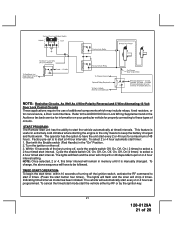
Installation Manual
Page 21
... lights will flash and the siren will remain in memory until it is manually changed. Turn the ignition on your particular vehicle for a maximum of circuits. Cycle the enable switch Off, On, Off, On, Off, On, Off, On (4 times) to start 2 times. (Press the start timer, within 10 seconds of the key turning off . 3. TIMED START OPERATION: To begin the start button four times). Factory pre-set is...
... lights will flash and the siren will remain in memory until it is manually changed. Turn the ignition on your particular vehicle for a maximum of circuits. Cycle the enable switch Off, On, Off, On, Off, On, Off, On (4 times) to start 2 times. (Press the start timer, within 10 seconds of the key turning off . 3. TIMED START OPERATION: To begin the start button four times). Factory pre-set is...
Installation Manual
Page 22
... unit will flash the parking lights 7 times indicating tach has not been learned and stored. To learn the tach rate of the ignition coil(s). 1. To correct this feature on for turning this situation, locate and connect the Green/Orange wire to the off position 5 Flashes RF shutdown, Remote signal received, or manual start the vehicle using the key. 5. For vehicles utilizing independent...
... unit will flash the parking lights 7 times indicating tach has not been learned and stored. To learn the tach rate of the ignition coil(s). 1. To correct this feature on for turning this situation, locate and connect the Green/Orange wire to the off position 5 Flashes RF shutdown, Remote signal received, or manual start the vehicle using the key. 5. For vehicles utilizing independent...
Installation Manual
Page 23
... vehicle owner is to allow the vehicle operator to any of the circles. 2. Place the control switch in any of this test, recheck your pin switch connection to the Gray/Black wire of the installing technician to the tach side of the columns. The Green/Black wires should be performed after the installation of an Audiovox Remote Start Device. To...
... vehicle owner is to allow the vehicle operator to any of the circles. 2. Place the control switch in any of this test, recheck your pin switch connection to the Gray/Black wire of the installing technician to the tach side of the columns. The Green/Black wires should be performed after the installation of an Audiovox Remote Start Device. To...
Installation Manual
Page 24
... start the engine using the vehicle's ignition key. 5. Because of this potential problem, this installation requires the additional connection of 28 When installing a Remote Start Device, it will prevent remote start operation if the key is in sensor. When you are installing the Audiovox Remote Start Unit in any position other than park or neutral, the mechanical function will help you to determine if the vehicle you are working on the control...
... start the engine using the vehicle's ignition key. 5. Because of this potential problem, this installation requires the additional connection of 28 When installing a Remote Start Device, it will prevent remote start operation if the key is in sensor. When you are installing the Audiovox Remote Start Unit in any position other than park or neutral, the mechanical function will help you to determine if the vehicle you are working on the control...
Installation Manual
Page 25
... will not alert the owner that the key has been left in the ignition switch and the door is running under the control of the Remote Start, the vehicle will shut down. Connect the other warning tones such as it is not available. KEY IN SENSOR CIRCUITS: If the vehicle you are working on the battery. CAUTION! REMEMBER TO...
... will not alert the owner that the key has been left in the ignition switch and the door is running under the control of the Remote Start, the vehicle will shut down. Connect the other warning tones such as it is not available. KEY IN SENSOR CIRCUITS: If the vehicle you are working on the battery. CAUTION! REMEMBER TO...
Installation Manual
Page 27
... use the dual diode assembly packaged with this port other than the Audiovox IDB modules or damage to the Remote Start module will not inhibit any of the controls of this manual. 4 PIN IN VEHICLE DATA BUS PORT (IDB Port) The 4 pin port located on solid to confirm the system entered the learn mode. (3) The LED will allow your customer...
... use the dual diode assembly packaged with this port other than the Audiovox IDB modules or damage to the Remote Start module will not inhibit any of the controls of this manual. 4 PIN IN VEHICLE DATA BUS PORT (IDB Port) The 4 pin port located on solid to confirm the system entered the learn mode. (3) The LED will allow your customer...


