Installation Manual
Page 3
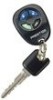
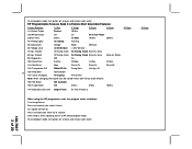
... or press and release valet switch. 6 Chirps RF Programmable Features Bank 3 Is Remote Start Selectable Features: Feature Selection 1 Chirp 2 Chirps 3 Chirps 4 Chirps 1st Defrost Output Pulsed 10 Mins 2nd RF Start Chirp Off On On & Car Finder 3rd Run Time 5 Mins 10 Mins 15 Mins 20 Mins 4th Parking Lights... On Steady Flashing 5th Input Check Voltage Tach DBI Tach 6th Voltage Level >0.5V B4 Start < 0.5V B4 Start 7th Ign. 2 Select Off...
... or press and release valet switch. 6 Chirps RF Programmable Features Bank 3 Is Remote Start Selectable Features: Feature Selection 1 Chirp 2 Chirps 3 Chirps 4 Chirps 1st Defrost Output Pulsed 10 Mins 2nd RF Start Chirp Off On On & Car Finder 3rd Run Time 5 Mins 10 Mins 15 Mins 20 Mins 4th Parking Lights... On Steady Flashing 5th Input Check Voltage Tach DBI Tach 6th Voltage Level >0.5V B4 Start < 0.5V B4 Start 7th Ign. 2 Select Off...

Installation Manual
Page 4
... 3 seconds, turn ignition Off, On, Off, On Short chirp, then 2 long chirps This Action Accesses Feature Bank 3 Remote Start Selectable Features Press the valet switch one time Press transmitter Lock button to change or Press and release the valet switch Press transmitter...engine 15 sec delay 4 chirps = unit set for diesel engine 20 sec delay 1 chirp = transponder output while R/S active 2 chirps = transponder output during start only 3 chirps = transponder output until ignition turned off Non Functional On This Unit 1 chirp = crank averaging w/voltage input checking 2 chirps = preset crank ...
... 3 seconds, turn ignition Off, On, Off, On Short chirp, then 2 long chirps This Action Accesses Feature Bank 3 Remote Start Selectable Features Press the valet switch one time Press transmitter Lock button to change or Press and release the valet switch Press transmitter...engine 15 sec delay 4 chirps = unit set for diesel engine 20 sec delay 1 chirp = transponder output while R/S active 2 chirps = transponder output during start only 3 chirps = transponder output until ignition turned off Non Functional On This Unit 1 chirp = crank averaging w/voltage input checking 2 chirps = preset crank ...
Installation Manual
Page 5
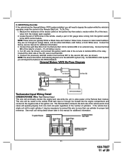
... (dashboard) of the vehicle for the safety shut down in serious personal injury and property damage. Although this combination Keyless Entry/Remote Start unit is away from water drain paths. INSTALLATION OF THE MAJOR COMPONENTS: CONTROL MODULE: Select a mounting location inside the passenger ...double stick tape is fully seated. For direct mounting, a 1/4" hole must be visable from below the dashboard for overriding the remote start unit when the vehicle is allowed for windshield glass as some newer vehicles utilize a metallic shielded window glass that adequate clearance ...
... (dashboard) of the vehicle for the safety shut down in serious personal injury and property damage. Although this combination Keyless Entry/Remote Start unit is away from water drain paths. INSTALLATION OF THE MAJOR COMPONENTS: CONTROL MODULE: Select a mounting location inside the passenger ...double stick tape is fully seated. For direct mounting, a 1/4" hole must be visable from below the dashboard for overriding the remote start unit when the vehicle is allowed for windshield glass as some newer vehicles utilize a metallic shielded window glass that adequate clearance ...
Installation Manual
Page 6
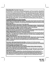
... USED IN COMBINATION ON EACH POWER WIRE AS SHOWN BELOW. This Remote Start System is received with Automatic Transmission Vehicles Only! The unit provides wait to start input for glow plug pre-heat which will crank the car when the RF signal is designed for use with no delay. Verification...gear. This wire will have +12 volts when the ignition switch is the responsibility of the installing technician to test the remote start unit and assure that the vehicle cannot start solenoid wire of the ignition switch harness. Fused RED w/ WHITE TRACE WIRE: + 12 volt Battery 1 Source Locate ...
... USED IN COMBINATION ON EACH POWER WIRE AS SHOWN BELOW. This Remote Start System is received with Automatic Transmission Vehicles Only! The unit provides wait to start input for glow plug pre-heat which will crank the car when the RF signal is designed for use with no delay. Verification...gear. This wire will have +12 volts when the ignition switch is the responsibility of the installing technician to test the remote start unit and assure that the vehicle cannot start solenoid wire of the ignition switch harness. Fused RED w/ WHITE TRACE WIRE: + 12 volt Battery 1 Source Locate ...
Installation Manual
Page 10
...are a chassis ground switched system, connect (1) of the cut wire to terminal #30 and the other wire that becomes active 3 seconds before the Remote Start unit is required to a fused + 12 volt battery source. Cut the shock sensor trigger wire and connect one end of the White wires to.... Switch LIGHT BLUE Wire: Ignition 3 / Shock Disable Output This wire provides a 300mA ground output that it is not shunted during the Remote Start activation period, then vibration from any other end of the alarm system. The Light Blue wire can cause the alarm to accommodate the following ...
...are a chassis ground switched system, connect (1) of the cut wire to terminal #30 and the other wire that becomes active 3 seconds before the Remote Start unit is required to a fused + 12 volt battery source. Cut the shock sensor trigger wire and connect one end of the White wires to.... Switch LIGHT BLUE Wire: Ignition 3 / Shock Disable Output This wire provides a 300mA ground output that it is not shunted during the Remote Start activation period, then vibration from any other end of the alarm system. The Light Blue wire can cause the alarm to accommodate the following ...
Installation Manual
Page 11
NOTE: These wires are typically White w/ Black trace and Violet w/ Yellow trace, however in most cases will require the Audiovox AS-PASS II Module. Connect terminal #85 of the relay to the second (#2) wire (as shown), and connect the ignition switch side of 20 Connect ... under power of the vehicle and in later model Cadillacs, they are either both Black, both Yellow, or both White wires. This Remote Start unit learns the tach rate of the Remote Start module. If the vehicle has a single coil unit for proper tach reference. For GM PASS LOCK System you will continually monitor...
NOTE: These wires are typically White w/ Black trace and Violet w/ Yellow trace, however in most cases will require the Audiovox AS-PASS II Module. Connect terminal #85 of the relay to the second (#2) wire (as shown), and connect the ignition switch side of 20 Connect ... under power of the vehicle and in later model Cadillacs, they are either both Black, both Yellow, or both White wires. This Remote Start unit learns the tach rate of the Remote Start module. If the vehicle has a single coil unit for proper tach reference. For GM PASS LOCK System you will continually monitor...
Installation Manual
Page 12
... to a high current circuit such as when the transmitter is used . When the unit is selected for continuous and the vehicle is started via the Remote Start, this wire must be used with a 1 Amp Fuse when connecting to as possible. When the unit is selected for transponder on ... crank sequence to control the way in a Gasoline vehicle, this wire will provide a 1 second 300 mA pulsed ground output 1.5 second before the remote start input, then 500mS later the starter will provide a 300 mA ground output while the starter output of feature Bank 3 Feature #11. This will ...
... to a high current circuit such as when the transmitter is used . When the unit is selected for continuous and the vehicle is started via the Remote Start, this wire must be used with a 1 Amp Fuse when connecting to as possible. When the unit is selected for transponder on ... crank sequence to control the way in a Gasoline vehicle, this wire will provide a 1 second 300 mA pulsed ground output 1.5 second before the remote start input, then 500mS later the starter will provide a 300 mA ground output while the starter output of feature Bank 3 Feature #11. This will ...
Installation Manual
Page 13
... the control module. WARNING ! Anytime the vehicle is running under the power of the ignition key, only while under control of the Remote Start and Channel 4 is accessed. WARNING: Connecting the light blue/green to the high current switched output of the receiver is activated, then...pulses to ground via an independent RF channel from the keychain transmitter. This is activated by the setting of feature # 1 of the remote start trigger inputs, will damage the control module. Pressing the pre-programmed transmitter button(s) will access channel four and will remain active, for...
... the control module. WARNING ! Anytime the vehicle is running under the power of the ignition key, only while under control of the Remote Start and Channel 4 is accessed. WARNING: Connecting the light blue/green to the high current switched output of the receiver is activated, then...pulses to ground via an independent RF channel from the keychain transmitter. This is activated by the setting of feature # 1 of the remote start trigger inputs, will damage the control module. Pressing the pre-programmed transmitter button(s) will access channel four and will remain active, for...
Installation Manual
Page 14
...terminal 87 to the vehicle's horn switch output, and connect relay terminal 30 to beep the vehicle's horn. TIMED START PROGRAM: The Remote Start unit has the ability to start module. Start By Holding the Pushbutton Switch On. 2. or 3b) Within 10 seconds of turning the ignition switch off , ...Black Trace Wire: External Trigger Input The Dark Blue/Black trace wire allows the remote start at timed intervals. Factory pre-set . NOTE: Once selected, 2 or 4, this wire to a ground pulsed output from a "POSSE/CAR-LINK" paging system or similar device. This is a transistorized, low current ...
...terminal 87 to the vehicle's horn switch output, and connect relay terminal 30 to beep the vehicle's horn. TIMED START PROGRAM: The Remote Start unit has the ability to start module. Start By Holding the Pushbutton Switch On. 2. or 3b) Within 10 seconds of turning the ignition switch off , ...Black Trace Wire: External Trigger Input The Dark Blue/Black trace wire allows the remote start at timed intervals. Factory pre-set . NOTE: Once selected, 2 or 4, this wire to a ground pulsed output from a "POSSE/CAR-LINK" paging system or similar device. This is a transistorized, low current ...
Installation Manual
Page 15
The vehicle will learn tach; 1. The Remote Car Starter will automatically start attempt. Immediately turn on the last remote start every 2 or 4 hours as indicated below. Release the program push-button switch. Diagnostics: 1. The indications are as follows. 1 Flash 5, 10, 15, or ... mode has been initiated. To achieve optimum performance the coil signals must connect to the (Green) or (Orange/Green) tach input of the Audiovox remote start timer, within 10 seconds of the columns. When the unit senses the tach signal, the parking lights will have 0 volts with vehicles that ...
The vehicle will learn tach; 1. The Remote Car Starter will automatically start attempt. Immediately turn on the last remote start every 2 or 4 hours as indicated below. Release the program push-button switch. Diagnostics: 1. The indications are as follows. 1 Flash 5, 10, 15, or ... mode has been initiated. To achieve optimum performance the coil signals must connect to the (Green) or (Orange/Green) tach input of the Audiovox remote start timer, within 10 seconds of the columns. When the unit senses the tach signal, the parking lights will have 0 volts with vehicles that ...
Installation Manual
Page 16
... by one again. TESTING YOUR INSTALLATION: W A R N I N G ! ! To test the integrity of the Audiovox Remote Start Unit. The car should be connected to prevent operation of the Remote Start Unit regardless of an Audiovox Remote Start Device. If the unit fails this circuit: 1. Consideration for the placement of the Yellow Start Wire. Temporarily disconnect the Brown/Black positive shut down position...
... by one again. TESTING YOUR INSTALLATION: W A R N I N G ! ! To test the integrity of the Audiovox Remote Start Unit. The car should be connected to prevent operation of the Remote Start Unit regardless of an Audiovox Remote Start Device. If the unit fails this circuit: 1. Consideration for the placement of the Yellow Start Wire. Temporarily disconnect the Brown/Black positive shut down position...
Installation Manual
Page 17
...vehicles or, locate the equivalent reference wire in the vehicle you cannot locate the ECM reference wire, there are installing the Audiovox Remote Start Unit in gear but offers no consideration for this vehicle. The reference diagram below will be connected to the drive position... or be connected to determine if the vehicle you are working on has this time move the gear selector to the Remote Start Unit. To connect the Audiovox remote start , failing this installation requires the additional connection of the gear selector position. WA R N I N G ! ! Because of this ...
...vehicles or, locate the equivalent reference wire in the vehicle you cannot locate the ECM reference wire, there are installing the Audiovox Remote Start Unit in gear but offers no consideration for this vehicle. The reference diagram below will be connected to the drive position... or be connected to determine if the vehicle you are working on has this time move the gear selector to the Remote Start Unit. To connect the Audiovox remote start , failing this installation requires the additional connection of the gear selector position. WA R N I N G ! ! Because of this ...
Installation Manual
Page 18
...installation using either alternative. Circuits may be connected to the Gray/Black wire of a vehicle utilizing an electrical neutral start switch and is inconsistent with the Audiovox Remote Start Unit as it must be energized causing a 150mA drain on reminder. Cut this wire and connect the ignition ...battery. Method 2 will allow the safety required for an alarm trigger input, be fully explained to maintain the integrity of the Audiovox Remote Start Unit. Cut this wire and connect the ignition cylinder side to the key in any gear other than Park or Neutral while...
...installation using either alternative. Circuits may be connected to the Gray/Black wire of a vehicle utilizing an electrical neutral start switch and is inconsistent with the Audiovox Remote Start Unit as it must be energized causing a 150mA drain on reminder. Cut this wire and connect the ignition ...battery. Method 2 will allow the safety required for an alarm trigger input, be fully explained to maintain the integrity of the Audiovox Remote Start Unit. Cut this wire and connect the ignition cylinder side to the key in any gear other than Park or Neutral while...
Installation Manual
Page 19
...blue, red, black, & white harness and connect to insure proper operation. 6. Apply the Caution Labels supplied with the Audiovox Remote Start Unit as shown in this kit to the Remote Start Negative Safety Shut down circuit. Check the vehicle's wipers, lights, horn, etc.... Replace all panels that connects the ... or the unit will not operate. 4 Pin Upgrade Data Bus/Flash Logic Module: If you have confirmed the operation of the Audiovox Remote Start unit and tested all hot and moving parts that the chosen mounting location will allow your customer to the ignition cylinder . Retest...
...blue, red, black, & white harness and connect to insure proper operation. 6. Apply the Caution Labels supplied with the Audiovox Remote Start Unit as shown in this kit to the Remote Start Negative Safety Shut down circuit. Check the vehicle's wipers, lights, horn, etc.... Replace all panels that connects the ... or the unit will not operate. 4 Pin Upgrade Data Bus/Flash Logic Module: If you have confirmed the operation of the Audiovox Remote Start unit and tested all hot and moving parts that the chosen mounting location will allow your customer to the ignition cylinder . Retest...


