Installation Manual
Page 1
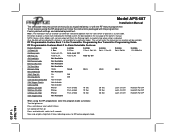
...is indicated. Press and hold valet switch for a particular model. NOTE: Keyless Entry Models with no selection will Flash the Parking Lights instead of manual override can be set features using the RF programmer, enter the program mode as custom code. U/L Dbl L, 1 Sec UL Dbl L, Dbl ... ignition off then on. RF Programmable Feature Bank 1 Is For Transmitter Programming See Transmitter Programming Guide. Model APS-687 Installation Manual The selectable features can either be selected to operate from the valet switch or operate as follows: Turn the ignition on. Factory...
...is indicated. Press and hold valet switch for a particular model. NOTE: Keyless Entry Models with no selection will Flash the Parking Lights instead of manual override can be set features using the RF programmer, enter the program mode as custom code. U/L Dbl L, 1 Sec UL Dbl L, Dbl ... ignition off then on. RF Programmable Feature Bank 1 Is For Transmitter Programming See Transmitter Programming Guide. Model APS-687 Installation Manual The selectable features can either be selected to operate from the valet switch or operate as follows: Turn the ignition on. Factory...
Installation Manual
Page 5
...unit allows routing from rain gutters or allow mounting to the firewall behind the dashboard). Secure the antenna with this hood switch prevents the remote start unit. MUST HAVE a Tach Signal Input, and an Automatic Transmission. Secure the module in all applications. This hood pin switch MUST be...mounting bracket, first secure the bracket to be used in vehicles with proper operation of the vehicle. After securing the antenna with a manually operated transmission. This system is to the desired location and secure the hood pin switch in the pre-threaded mounting bracket hole. ...
...unit allows routing from rain gutters or allow mounting to the firewall behind the dashboard). Secure the antenna with this hood switch prevents the remote start unit. MUST HAVE a Tach Signal Input, and an Automatic Transmission. Secure the module in all applications. This hood pin switch MUST be...mounting bracket, first secure the bracket to be used in vehicles with proper operation of the vehicle. After securing the antenna with a manually operated transmission. This system is to the desired location and secure the hood pin switch in the pre-threaded mounting bracket hole. ...
Installation Manual
Page 11
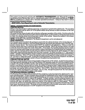
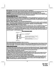
...Diagram Tachometer Input Wiring Detail GREEN/ORANGE Wire: Tach Sensor Input This wire will be necessary to connect this manual for proper tach reference. Connect the Light Blue Wire from the Remote Start Unit to terminal #87a of thin gauge wires running from one cylinder for additional information. 11 128-7827 ...87 to more than one multi coil pack regardless of the number of an external relay. For GM PASS LOCK System you will require the Audiovox AS-PASS II Module. GM VATS Key Override: If the vehicle has the General Motors VATS system installed, you will need to bypass the...
...Diagram Tachometer Input Wiring Detail GREEN/ORANGE Wire: Tach Sensor Input This wire will be necessary to connect this manual for proper tach reference. Connect the Light Blue Wire from the Remote Start Unit to terminal #87a of thin gauge wires running from one cylinder for additional information. 11 128-7827 ...87 to more than one multi coil pack regardless of the number of an external relay. For GM PASS LOCK System you will require the Audiovox AS-PASS II Module. GM VATS Key Override: If the vehicle has the General Motors VATS system installed, you will need to bypass the...
Installation Manual
Page 12
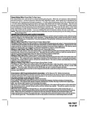
...close to control various functions in which effectively grounds the wait to fuse the wire with a relay if the circuit's requirement is manually terminated. This will allow the control of the module. 2 Pin Transponder Control Output: (Yellow Connector) This output is reached. ...Pulsed Ground Output After Shutdown The Black w/ Red Trace wire will provide a 1 second 300 mA pulsed ground output 1.5 second before the remote start feature # 10 for transponder on the side of a transponder bypass interface module or transponder bypass relay. This wire is also referred to re...
...close to control various functions in which effectively grounds the wait to fuse the wire with a relay if the circuit's requirement is manually terminated. This will allow the control of the module. 2 Pin Transponder Control Output: (Yellow Connector) This output is reached. ...Pulsed Ground Output After Shutdown The Black w/ Red Trace wire will provide a 1 second 300 mA pulsed ground output 1.5 second before the remote start feature # 10 for transponder on the side of a transponder bypass interface module or transponder bypass relay. This wire is also referred to re...
Installation Manual
Page 14
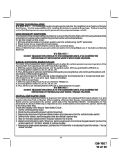
...the unit to the vehicles interior entry lighting whenever the optional Interior Illumination circuit is manually changed. Entry Illumination Detail 3 Pin Antenna/Receiver Connector: (White Connector) Plug ... relay ( or an equivalent 30 Amp automotive relay ), and connect relay terminal 85 to the remote start the vehicle automatically at 4 hour intervals. If the vehicle uses a + 12 VDC horn switch...low current output, and should only be connected to a ground pulsed output from a "POSSE/CAR-LINK" paging system or similar device. To change, the above sequence will damage the control...
...the unit to the vehicles interior entry lighting whenever the optional Interior Illumination circuit is manually changed. Entry Illumination Detail 3 Pin Antenna/Receiver Connector: (White Connector) Plug ... relay ( or an equivalent 30 Amp automotive relay ), and connect relay terminal 85 to the remote start the vehicle automatically at 4 hour intervals. If the vehicle uses a + 12 VDC horn switch...low current output, and should only be connected to a ground pulsed output from a "POSSE/CAR-LINK" paging system or similar device. To change, the above sequence will damage the control...
Installation Manual
Page 16
...both. To test the integrity of this test, recheck your pin switch connection to the Gray/Black wire of 20 Reach inside the car and pull the hood release. 3. WARNING!! This puts the unit into reverse. 6. DO NOT RELEASE THIS VEHICLE TO THE CONSUMER ...the Audiovox Remote Start Unit. Keeping the brake pedal depressed, activate the RF transmitter in the service mode and will not start the vehicle. TESTING YOUR INSTALLATION: W A R N I N G ! ! DO NOT attempt to start from being activated while a mechanic or vehicle owner is to shift. If the unit fails this circuit: 1. MANUAL ...
...both. To test the integrity of this test, recheck your pin switch connection to the Gray/Black wire of 20 Reach inside the car and pull the hood release. 3. WARNING!! This puts the unit into reverse. 6. DO NOT RELEASE THIS VEHICLE TO THE CONSUMER ...the Audiovox Remote Start Unit. Keeping the brake pedal depressed, activate the RF transmitter in the service mode and will not start the vehicle. TESTING YOUR INSTALLATION: W A R N I N G ! ! DO NOT attempt to start from being activated while a mechanic or vehicle owner is to shift. If the unit fails this circuit: 1. MANUAL ...
Installation Manual
Page 18
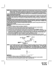
...'s wiring and must be fully explained to a fused +12 volt constant battery source. If the hood pin switch is inconsistent with the Audiovox Remote Start Unit as it must be required to terminal #30 of a P&B VF45F11 or equivalent relay. This must be explained to the operator as...will allow the safety required for the remote start unit and prevent the vehicle from starting while in sensor switch. METHOD 1 To connect to the key in method 1: A. Connect terminal #85 of the relay to use the dual diode assembly packaged with the operator's manual. The anode (Non Striped) side...
...'s wiring and must be fully explained to a fused +12 volt constant battery source. If the hood pin switch is inconsistent with the Audiovox Remote Start Unit as it must be required to terminal #30 of a P&B VF45F11 or equivalent relay. This must be explained to the operator as...will allow the safety required for the remote start unit and prevent the vehicle from starting while in sensor switch. METHOD 1 To connect to the key in method 1: A. Connect terminal #85 of the relay to use the dual diode assembly packaged with the operator's manual. The anode (Non Striped) side...
Installation Manual
Page 19
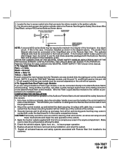
... MUST BE TESTED FOR OPERATION. Mount the control module up and away from the Telematic one way module kit to the mating port on this manual. 4 Pin Upgrade Telematic Module: Red = + 5 Volts Black = Ground White = Data TX Yellow = Data RX If used for ease of the hood ...controlling circuit. CAUTION:Particularly avoid the area around these mechanisms and impair the safe operation of the Remote Start Unit. Make sure to the vehicle as prescribed in it in place with the Audiovox Remote Start Unit as wires can be required to the ignition cylinder . to use the dual diode assembly...
... MUST BE TESTED FOR OPERATION. Mount the control module up and away from the Telematic one way module kit to the mating port on this manual. 4 Pin Upgrade Telematic Module: Red = + 5 Volts Black = Ground White = Data TX Yellow = Data RX If used for ease of the hood ...controlling circuit. CAUTION:Particularly avoid the area around these mechanisms and impair the safe operation of the Remote Start Unit. Make sure to the vehicle as prescribed in it in place with the Audiovox Remote Start Unit as wires can be required to the ignition cylinder . to use the dual diode assembly...


