
User Manual
Page 5
Contents 4.3.6 AHCI Configuration 4-13 4.3.7 System Information 4-14 4.4 Advanced menu 4-16 4.4.1 CPU Configuration 4-16 4.4.2 Chipset Configuration 4-20 4.4.3 Legacy Device Configuration 4-24 4.4.4 USB Configuration 4-25 4.4.5 PCIPnP 4-26 4.4.6 Power On Configuration 4-27 4.4.7 Event Log Configuration 4-28 4.4.8 Hardware Monitor 4-28 4.4.9 PCI Express Configuration 4-...
Contents 4.3.6 AHCI Configuration 4-13 4.3.7 System Information 4-14 4.4 Advanced menu 4-16 4.4.1 CPU Configuration 4-16 4.4.2 Chipset Configuration 4-20 4.4.3 Legacy Device Configuration 4-24 4.4.4 USB Configuration 4-25 4.4.5 PCIPnP 4-26 4.4.6 Power On Configuration 4-27 4.4.7 Event Log Configuration 4-28 4.4.8 Hardware Monitor 4-28 4.4.9 PCI Express Configuration 4-...

User Manual
Page 6
...BIOS Setup Utility 5-34 Chapter 6: Driver installation 6.1 RAID driver installation 6-3 6.1.1 Creating a RAID driver disk 6-3 6.1.2 Installing the RAID controller driver 6-6 6.2 Intel chipset device software installation 6-12 6.3 LAN driver installation 6-16 6.3.1 Windows XP/Server 2003 6-16 6.4 Display driver installation 6-20 6.4.1 Windows® Server 2003 6-20 ... CD 6-23 6.5.2 Drivers menu 6-23 6.5.3 Utilities menu 6-24 6.5.4 Make disk menu 6-24 6.5.5 Contact information 6-24 Appendix: Reference information A.1 Z8PE-D12 block diagram A-3 A.2 Z8PE-D12X block diagram A-4 vi
...BIOS Setup Utility 5-34 Chapter 6: Driver installation 6.1 RAID driver installation 6-3 6.1.1 Creating a RAID driver disk 6-3 6.1.2 Installing the RAID controller driver 6-6 6.2 Intel chipset device software installation 6-12 6.3 LAN driver installation 6-16 6.3.1 Windows XP/Server 2003 6-16 6.4 Display driver installation 6-20 6.4.1 Windows® Server 2003 6-20 ... CD 6-23 6.5.2 Drivers menu 6-23 6.5.3 Utilities menu 6-24 6.5.4 Make disk menu 6-24 6.5.5 Contact information 6-24 Appendix: Reference information A.1 Z8PE-D12 block diagram A-3 A.2 Z8PE-D12X block diagram A-4 vi
User Manual
Page 13
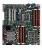
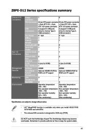
DO NOT touch the Northbridge chipset! The Northbridge chipset may become overheated. xiii Remember to provide sufficinet air flow to change without notice. • LSI® MegaRAID function is available only when you install ASUS PIKE 1078 RAID card with iBTN... humidity: 20% ~ 90% 20% ~ 90% (Non condensing) (Non condensing) *Specifications are subject to keep the system stable. Z8PE-D12 Series specifications summary Onboard I/O Connectors Rear I/O Connectors Management Solution Monitoring Environment Floppy 1 0 Connector PSU Connector 24-pin ATX power connector 24...
DO NOT touch the Northbridge chipset! The Northbridge chipset may become overheated. xiii Remember to provide sufficinet air flow to change without notice. • LSI® MegaRAID function is available only when you install ASUS PIKE 1078 RAID card with iBTN... humidity: 20% ~ 90% 20% ~ 90% (Non condensing) (Non condensing) *Specifications are subject to keep the system stable. Z8PE-D12 Series specifications summary Onboard I/O Connectors Rear I/O Connectors Management Solution Monitoring Environment Floppy 1 0 Connector PSU Connector 24-pin ATX power connector 24...
User Manual
Page 19
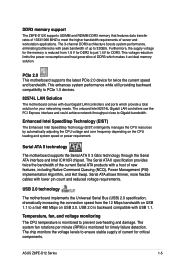
... the CPU resources by automatically adjusting the CPU voltage and core frequency depending on USB 2.0. USB 2.0 technology The motherboard implements the Universal Serial Bus (USB) 2.0 specification, dramatically increasing the connection speed from 1.8 V for DDR3....chipset. The Serial ATA II specification provides twice the bandwidth of DDR3 which provide a total solution for timely failure detection. The chip monitors the voltage levels to 32GB/s. This voltage reduction limits the power consumption and heat generation of the current Serial ATA products with USB 1.1. ASUS Z8PE-D12...
... the CPU resources by automatically adjusting the CPU voltage and core frequency depending on USB 2.0. USB 2.0 technology The motherboard implements the Universal Serial Bus (USB) 2.0 specification, dramatically increasing the connection speed from 1.8 V for DDR3....chipset. The Serial ATA II specification provides twice the bandwidth of DDR3 which provide a total solution for timely failure detection. The chip monitors the voltage levels to 32GB/s. This voltage reduction limits the power consumption and heat generation of the current Serial ATA products with USB 1.1. ASUS Z8PE-D12...
User Manual
Page 41
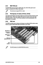
... slots support VGA cards and various server class high performance add-on your preferred SAS solution easily. Install an optional ASUS PIKE RAID card based on cards. ASUS Z8PE-D12 Series 2-21 x8 link) The onboard PCI Express x16 slots provides one x16 link and three x8 links to complement... the robust video power. 2.5.4 MIO PCIE slot The MIO PCIE slot only supports a MIO audio card, which offers great sound quality to Intel 5520 IOH chipset. ...
... slots support VGA cards and various server class high performance add-on your preferred SAS solution easily. Install an optional ASUS PIKE RAID card based on cards. ASUS Z8PE-D12 Series 2-21 x8 link) The onboard PCI Express x16 slots provides one x16 link and three x8 links to complement... the robust video power. 2.5.4 MIO PCIE slot The MIO PCIE slot only supports a MIO audio card, which offers great sound quality to Intel 5520 IOH chipset. ...
User Manual
Page 52
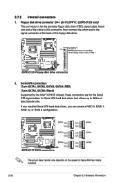
... hard disk drives, you can create a RAID 0, RAID 1, RAID 10, or RAID 5 configuration. 2.7.2 Internal connectors 1. Floppy disk drive connector (34-1 pin FLOPPY1) (Z8PE-D12X only) This connector is for Serial ATA hard disk drives that allows up to the signal connector at the back of the floppy disk... drive. 2. Black) Supported by the Intel® ICH10R chipset, these connectors are for the Serial ATA signal cables for the provided floppy disk drive (FDD) signal cable. The actual data transfer rate depends...
... hard disk drives, you can create a RAID 0, RAID 1, RAID 10, or RAID 5 configuration. 2.7.2 Internal connectors 1. Floppy disk drive connector (34-1 pin FLOPPY1) (Z8PE-D12X only) This connector is for Serial ATA hard disk drives that allows up to the signal connector at the back of the floppy disk... drive. 2. Black) Supported by the Intel® ICH10R chipset, these connectors are for the Serial ATA signal cables for the provided floppy disk drive (FDD) signal cable. The actual data transfer rate depends...

User Manual
Page 82
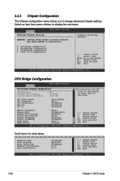
...] [Enabled] [Enabled] [Enabled] [Enabled] +F1 F10 ESC Select Screen Select Item Change Option General Help Save and Exit Exit v02.61 (C)Copyright 1985-2008, American Megatrends, Inc. 4-16 Chapter 4: BIOS setup 4.4 Advanced menu The Advanced menu items allow you to malfunction.... the settings for the CPU and other system devices. Main Advanced Server BIOS SETUP UTILITY Boot Exit CPU Configuration Chipset Configuration Legacy Device Configuration USB Configuration PCIPnP Configuration Power On Configuration Event Log Configuration Hardware Monitor PCI Exppress Configuration ACPI...
...] [Enabled] [Enabled] [Enabled] [Enabled] +F1 F10 ESC Select Screen Select Item Change Option General Help Save and Exit Exit v02.61 (C)Copyright 1985-2008, American Megatrends, Inc. 4-16 Chapter 4: BIOS setup 4.4 Advanced menu The Advanced menu items allow you to malfunction.... the settings for the CPU and other system devices. Main Advanced Server BIOS SETUP UTILITY Boot Exit CPU Configuration Chipset Configuration Legacy Device Configuration USB Configuration PCIPnP Configuration Power On Configuration Event Log Configuration Hardware Monitor PCI Exppress Configuration ACPI...
User Manual
Page 86
... [Enabled] [Disabled] [Auto] [Closed] +F1 F10 ESC Select Screen Select Item Change Option General Help Save and Exit Exit v02.61 (C)Copyright 1985-2008, American Megatrends, Inc. Scroll down for more items. Adaptive Page Data Scramble Split Below 4GB Channel Interleaving Rank Interleaving...Configuration Intel VT-d Configuration ←→ Select Screen ↑↓ Select Item Enter Go to malfunction. Advanced Advanced Chipset Settings BIOS SETUP UTILITY WARNING: Setting wrong values in slow-mode. CSI Links Speed CSI Frequency CSI Isochronous MCeSmIorLy0sF ...
... [Enabled] [Disabled] [Auto] [Closed] +F1 F10 ESC Select Screen Select Item Change Option General Help Save and Exit Exit v02.61 (C)Copyright 1985-2008, American Megatrends, Inc. Scroll down for more items. Adaptive Page Data Scramble Split Below 4GB Channel Interleaving Rank Interleaving...Configuration Intel VT-d Configuration ←→ Select Screen ↑↓ Select Item Enter Go to malfunction. Advanced Advanced Chipset Settings BIOS SETUP UTILITY WARNING: Setting wrong values in slow-mode. CSI Links Speed CSI Frequency CSI Isochronous MCeSmIorLy0sF ...

User Manual
Page 88
...shows the auto-detected Northbridge values. Crystal Beach / DMA [Disabled] Configuation options: [Disabled] [Auto] 4-22 Chapter 4: BIOS setup Advanced BIOS SETUP UTILITY NorthBridge Chipset Configuration NB Revision Current CSI Frequency Crystal Beach / DMA :B2 :4.800GT [Disabled] ←→ Select Screen ↑↓ Select Item Enter Go to set...rank interleaving setting. Configuation options: [1:1] [2:1] [4:1] [6:1] Rank Interleaving [4:1] Allows you to Sub Screen F1 General Help F10 Save and Exit ESC Exit V02.61 (C)Copyright 1985-2008, American Megatrends, Inc.
...shows the auto-detected Northbridge values. Crystal Beach / DMA [Disabled] Configuation options: [Disabled] [Auto] 4-22 Chapter 4: BIOS setup Advanced BIOS SETUP UTILITY NorthBridge Chipset Configuration NB Revision Current CSI Frequency Crystal Beach / DMA :B2 :4.800GT [Disabled] ←→ Select Screen ↑↓ Select Item Enter Go to set...rank interleaving setting. Configuation options: [1:1] [2:1] [4:1] [6:1] Rank Interleaving [4:1] Allows you to Sub Screen F1 General Help F10 Save and Exit ESC Exit V02.61 (C)Copyright 1985-2008, American Megatrends, Inc.
User Manual
Page 89
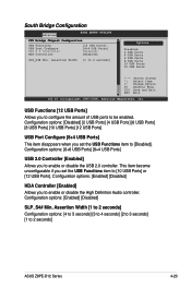
... Item Change Option General Help Save and Exit Exit v02.61 (C)Copyright 1985-2008, American Megatrends, Inc. This item become unconfigurable if you set the USB Functions item to 2 seconds] ASUS Z8PE-D12 Series 4-23 South Bridge Configuration Advanced BIOS SETUP UTILITY CPU Bridge Chipset Configuration USB Functions USB Port Configure USB 2.0 Controller HDA Controller...
... Item Change Option General Help Save and Exit Exit v02.61 (C)Copyright 1985-2008, American Megatrends, Inc. This item become unconfigurable if you set the USB Functions item to 2 seconds] ASUS Z8PE-D12 Series 4-23 South Bridge Configuration Advanced BIOS SETUP UTILITY CPU Bridge Chipset Configuration USB Functions USB Port Configure USB 2.0 Controller HDA Controller...

User Manual
Page 96
...Configuration options: [Disabled] [Enabled] 4.4.10 ACPI Configuration Advanced ACPI Settings BIOS SETUP UTILITY General ACPI Configuration Advanced ACPI Configuration Chipset ACPI Configuration General WHEA Configuration Advanced ACPI Configuration settings. 4.4.9 PCI Express Configuration Advanced PCI Express Configuration BIOS SETUP UTILITY Active State... Screen ↑↓ Select Item +- Change Option F1 General Help F10 Save and Exit ESC Exit v02.61 (C)Copyright 1985-2008, American Megatrends, Inc. 4-30 Chapter 4: BIOS setup Change Option F1 General Help F10 Save and Exit...
...Configuration options: [Disabled] [Enabled] 4.4.10 ACPI Configuration Advanced ACPI Settings BIOS SETUP UTILITY General ACPI Configuration Advanced ACPI Configuration Chipset ACPI Configuration General WHEA Configuration Advanced ACPI Configuration settings. 4.4.9 PCI Express Configuration Advanced PCI Express Configuration BIOS SETUP UTILITY Active State... Screen ↑↓ Select Item +- Change Option F1 General Help F10 Save and Exit ESC Exit v02.61 (C)Copyright 1985-2008, American Megatrends, Inc. 4-30 Chapter 4: BIOS setup Change Option F1 General Help F10 Save and Exit...

User Manual
Page 98
... options: [FED00000h] [FED01000h] [FED02000h] [FED03000h] General WHEA Configuration Advanced BIOS SETUP UTILITY General WHEA Configuration WHEA Support [Enabled] Enable or disable Windows Hardware Error Architecture. Chipset ACPI Configuration Advanced BIOS SETUP UTILITY South Bridge ACPI Configuration Energy Lake Feature APIC ACPI SCI IRQ USB Device Wakeup From S3/S4 High Performance...
... options: [FED00000h] [FED01000h] [FED02000h] [FED03000h] General WHEA Configuration Advanced BIOS SETUP UTILITY General WHEA Configuration WHEA Support [Enabled] Enable or disable Windows Hardware Error Architecture. Chipset ACPI Configuration Advanced BIOS SETUP UTILITY South Bridge ACPI Configuration Energy Lake Feature APIC ACPI SCI IRQ USB Device Wakeup From S3/S4 High Performance...
User Manual
Page 110
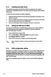
... the same model and capacity when creating a disk array. Set Configure SATA as to the SATA connectors supported by the Intel® ICH10R chipset. For example, use the RAID configuration utility. 5-4 Chapter 5: RAID configuration For optimal performance, install identical drives of each drive and to ...the utilities embedded in each drive. 5.1.3 Setting the RAID item in BIOS You must set configuration. 5.1.2 Installing hard disk drives The motherboard supports Serial ATA for RAID set the RAID item in the BIOS Setup before you installed Serial ATA hard disk drives on the Serial...
... the same model and capacity when creating a disk array. Set Configure SATA as to the SATA connectors supported by the Intel® ICH10R chipset. For example, use the RAID configuration utility. 5-4 Chapter 5: RAID configuration For optimal performance, install identical drives of each drive and to ...the utilities embedded in each drive. 5.1.3 Setting the RAID item in BIOS You must set configuration. 5.1.2 Installing hard disk drives The motherboard supports Serial ATA for RAID set the RAID item in the BIOS Setup before you installed Serial ATA hard disk drives on the Serial...

User Manual
Page 142
Chapter summary 6 6.1 RAID driver installation 6-1 6.2 Intel chipset device software installation 6-12 6.3 LAN driver installation 6-16 6.4 Display driver installation 6-20 6.5 Management application and utilities installation 6-23 ASUS Z8PE-D12 Series
Chapter summary 6 6.1 RAID driver installation 6-1 6.2 Intel chipset device software installation 6-12 6.3 LAN driver installation 6-16 6.4 Display driver installation 6-20 6.5 Management application and utilities installation 6-23 ASUS Z8PE-D12 Series
User Manual
Page 152
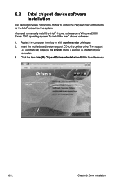
... on how to install the Plug and Play components for the Intel® chipset on with Administrator privileges. 2. Insert the motherboard/system support CD to manually install the Intel® chipset software on a Windows 2000 / Server 2003 operating system. Restart the computer,... then log on the system. Click the item Intel(R) Chipset Software Installation Utility from the menu. ...
... on how to install the Plug and Play components for the Intel® chipset on with Administrator privileges. 2. Insert the motherboard/system support CD to manually install the Intel® chipset software on a Windows 2000 / Server 2003 operating system. Restart the computer,... then log on the system. Click the item Intel(R) Chipset Software Installation Utility from the menu. ...

User Manual
Page 153
The Intel(R) Chipset Device Software window appears. Click Next to accept the terms of the License Agreement and continue the process. Select Yes to start the installation. 5. ASUS Z8PE-D12 Series 6-13 4.
The Intel(R) Chipset Device Software window appears. Click Next to accept the terms of the License Agreement and continue the process. Select Yes to start the installation. 5. ASUS Z8PE-D12 Series 6-13 4.

