
User Manual
Page 5
... Log Configuration 4-28 4.4.8 Hardware Monitor 4-28 4.4.9 PCI Express Configuration 4-30 4.4.10 ACPI Configuration 4-30 4.5 Server menu 4-33 4.5.1 Remote Access Configuration 4-33 4.6 Boot menu 4-35 4.6.1 Boot Device Priority 4-35 4.6.2 Removable Drives 4-36 4.6.3 Boot Settings Configuration 4-36 4.6.4 Security 4-38 4.7 Exit menu 4-40 Exit & Save Changes 4-40 Exit & Discard Changes 4-40 Discard Changes 4-40 Load Setup...
... Log Configuration 4-28 4.4.8 Hardware Monitor 4-28 4.4.9 PCI Express Configuration 4-30 4.4.10 ACPI Configuration 4-30 4.5 Server menu 4-33 4.5.1 Remote Access Configuration 4-33 4.6 Boot menu 4-35 4.6.1 Boot Device Priority 4-35 4.6.2 Removable Drives 4-36 4.6.3 Boot Settings Configuration 4-36 4.6.4 Security 4-38 4.7 Exit menu 4-40 Exit & Save Changes 4-40 Exit & Discard Changes 4-40 Discard Changes 4-40 Load Setup...

User Manual
Page 6
... disks to Non-RAID 5-30 5.3.5 5.3.6 Recovery Volume Options 5-31 Exiting the Intel® Matrix Storage Manager 5-32 6.3.7 Rebuilding the RAID 5-32 5.3.8 Setting the Boot array in the BIOS Setup Utility 5-34 Chapter 6: Driver installation 6.1 RAID driver installation 6-3 6.1.1 Creating a RAID driver disk 6-3 6.1.2 Installing the RAID controller driver ... support CD 6-23 6.5.2 Drivers menu 6-23 6.5.3 Utilities menu 6-24 6.5.4 Make disk menu 6-24 6.5.5 Contact information 6-24 Appendix: Reference information A.1 Z8PE-D12 block diagram A-3 A.2 Z8PE-D12X block diagram A-4 vi
... disks to Non-RAID 5-30 5.3.5 5.3.6 Recovery Volume Options 5-31 Exiting the Intel® Matrix Storage Manager 5-32 6.3.7 Rebuilding the RAID 5-32 5.3.8 Setting the Boot array in the BIOS Setup Utility 5-34 Chapter 6: Driver installation 6.1 RAID driver installation 6-3 6.1.1 Creating a RAID driver disk 6-3 6.1.2 Installing the RAID controller driver ... support CD 6-23 6.5.2 Drivers menu 6-23 6.5.3 Utilities menu 6-24 6.5.4 Make disk menu 6-24 6.5.5 Contact information 6-24 Appendix: Reference information A.1 Z8PE-D12 block diagram A-3 A.2 Z8PE-D12X block diagram A-4 vi
User Manual
Page 45
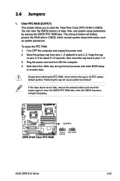
... can clear the CMOS memory of date, time, and system setup parameters by erasing the CMOS RTC RAM data. Hold down the key during the boot process and enter BIOS setup to pins 2-3. Plug the power cord and turn ON the computer. 4. Removing the cap will cause system... boot failure! 2.6 Jumpers 1. Except when clearing the RTC RAM, never remove the cap on pins 2-3 for about 5-10 seconds, then move the jumper again to clear the CMOS RTC RAM data. ASUS Z8PE-D12 Series 2-25 Clear RTC RAM (CLRTC1) This jumper allows you...
... can clear the CMOS memory of date, time, and system setup parameters by erasing the CMOS RTC RAM data. Hold down the key during the boot process and enter BIOS setup to pins 2-3. Plug the power cord and turn ON the computer. 4. Removing the cap will cause system... boot failure! 2.6 Jumpers 1. Except when clearing the RTC RAM, never remove the cap on pins 2-3 for about 5-10 seconds, then move the jumper again to clear the CMOS RTC RAM data. ASUS Z8PE-D12 Series 2-25 Clear RTC RAM (CLRTC1) This jumper allows you...
User Manual
Page 59
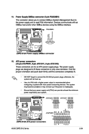
... ATXPWR1, 8-pin ATX12V1, 8-pin ATX12V2) These connectors are designed to connect the 24+8+8-pin power plugs; The system may become unstable or may not boot up . • Use of a PSU with a higher power output is inadequate. • Ensure that your power supply unit (PSU) can provide... proper orientation and push down firmly until the connectors completely fit. • DO NOT forget to fit these connectors in only one orientation. ASUS Z8PE-D12 Series 2-39 14. Power Supply SMBus connector (5-pin PSUSMB1) This connector allows you to connect SMBus (System Management Bus) to the power ...
... ATXPWR1, 8-pin ATX12V1, 8-pin ATX12V2) These connectors are designed to connect the 24+8+8-pin power plugs; The system may become unstable or may not boot up . • Use of a PSU with a higher power output is inadequate. • Ensure that your power supply unit (PSU) can provide... proper orientation and push down firmly until the connectors completely fit. • DO NOT forget to fit these connectors in only one orientation. ASUS Z8PE-D12 Series 2-39 14. Power Supply SMBus connector (5-pin PSUSMB1) This connector allows you to connect SMBus (System Management Bus) to the power ...

User Manual
Page 68
Chapter summary 4 4.1 Managing and updating your BIOS 4-1 4.2 BIOS setup program 4-8 4.3 Main menu 4-11 4.4 Advanced menu 4-17 4.5 Server menu 4-35 4.6 Boot menu 4-37 4.7 Exit menu 4-42 ASUS Z8PE-D12 Series
Chapter summary 4 4.1 Managing and updating your BIOS 4-1 4.2 BIOS setup program 4-8 4.3 Main menu 4-11 4.4 Advanced menu 4-17 4.5 Server menu 4-35 4.6 Boot menu 4-37 4.7 Exit menu 4-42 ASUS Z8PE-D12 Series
User Manual
Page 69
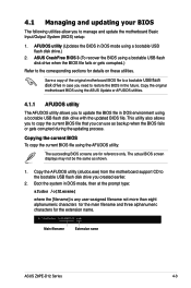
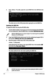
...ASUS Z8PE-D12 Series 4-3 4.1 Managing and updating your BIOS The following utilities allow you to copy the current BIOS file that you can use as shown. 1. This utility also allows you to manage and update the motherboard Basic Input/Output System (BIOS) setup: 1. Copy the original motherboard BIOS using the ASUS... for details on these utilities. Copy the AFUDOS utility (afudos.exe) from the motherboard support CD to update the BIOS file in DOS environment using a bootable USB flash disk drive.) 2. Boot the system in DOS mode using a bootable USB flash disk drive with the updated...
...ASUS Z8PE-D12 Series 4-3 4.1 Managing and updating your BIOS The following utilities allow you to copy the current BIOS file that you can use as shown. 1. This utility also allows you to manage and update the motherboard Basic Input/Output System (BIOS) setup: 1. Copy the original motherboard BIOS using the ASUS... for details on these utilities. Copy the AFUDOS utility (afudos.exe) from the motherboard support CD to update the BIOS file in DOS environment using a bootable USB flash disk drive.) 2. Boot the system in DOS mode using a bootable USB flash disk drive with the updated...
User Manual
Page 70
... All rights reserved. Version 1.19(ASUS V2.07(03.11.24BB)) Copyright (C) 2002 American Megatrends, Inc. Updating the BIOS file To update the BIOS file using the AFUDOS utility: 1. Copy the AFUDOS utility (afudos.exe) from the motherboard support CD to prevent system boot failure! 4-4 Chapter 4: BIOS setup...done Write to the USB flash disk drive. The utility copies the current BIOS file to file...... done Reading flash ...... Boot the system in DOS mode, then at the DOS prompt. 2. 3. Visit the ASUS website at www.asus.com and download the latest BIOS file for the motherboard.
... All rights reserved. Version 1.19(ASUS V2.07(03.11.24BB)) Copyright (C) 2002 American Megatrends, Inc. Updating the BIOS file To update the BIOS file using the AFUDOS utility: 1. Copy the AFUDOS utility (afudos.exe) from the motherboard support CD to prevent system boot failure! 4-4 Chapter 4: BIOS setup...done Write to the USB flash disk drive. The utility copies the current BIOS file to file...... done Reading flash ...... Boot the system in DOS mode, then at the DOS prompt. 2. 3. Visit the ASUS website at www.asus.com and download the latest BIOS file for the motherboard.
User Manual
Page 72
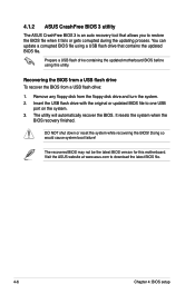
Prepare a USB flash drive containing the updated motherboard BIOS before using a USB flash drive that allows you to download the latest BIOS file. 4-6 Chapter 4: BIOS setup 4.1.2 ASUS CrashFree BIOS 3 utility The ASUS CrashFree BIOS 3 is an auto recovery tool that contains the updated BIOS file. Remove any...recovering the BIOS! You can update a corrupted BIOS file using this motherboard. The utility will automatically recover the BIOS. Doing so would cause system boot failure! Visit the ASUS website at www.asus.com to restore the BIOS file when it fails or gets corrupted...
Prepare a USB flash drive containing the updated motherboard BIOS before using a USB flash drive that allows you to download the latest BIOS file. 4-6 Chapter 4: BIOS setup 4.1.2 ASUS CrashFree BIOS 3 utility The ASUS CrashFree BIOS 3 is an auto recovery tool that contains the updated BIOS file. Remove any...recovering the BIOS! You can update a corrupted BIOS file using this motherboard. The utility will automatically recover the BIOS. Doing so would cause system boot failure! Visit the ASUS website at www.asus.com to restore the BIOS file when it fails or gets corrupted...
User Manual
Page 74
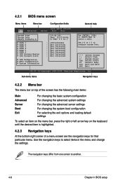
... are the navigation keys for that particular menu. 4.2.1 BIOS menu screen Menu items Menu bar Configuration fields General help Main Advanced BIOS SETUP UTILITY Server Boot Exit System Time [13:44:30] System Date [Wed, 12/17/2008] Legacy Diskette A [1.44M, 3.5 in.] SATA 1 SATA 2 SATA 3 SATA 4 SATA...] to select items in the menu and change the settings. Change Field Tab Select Field F1 General Help F10 Save and Exit ESC Exit v02.61 (C)Copyright 1985-2008, American Megatrends, Inc. Use the navigation keys to select a field. Use [+] or [-] to another. 4-8 Chapter 4: ...
... are the navigation keys for that particular menu. 4.2.1 BIOS menu screen Menu items Menu bar Configuration fields General help Main Advanced BIOS SETUP UTILITY Server Boot Exit System Time [13:44:30] System Date [Wed, 12/17/2008] Legacy Diskette A [1.44M, 3.5 in.] SATA 1 SATA 2 SATA 3 SATA 4 SATA...] to select items in the menu and change the settings. Change Field Tab Select Field F1 General Help F10 Save and Exit ESC Exit v02.61 (C)Copyright 1985-2008, American Megatrends, Inc. Use the navigation keys to select a field. Use [+] or [-] to another. 4-8 Chapter 4: ...
User Manual
Page 75
... the other items (Advanced, Power, Boot, and Exit) on any menu screen means that is a brief description of options. You cannot select an item that the item has a sub-menu. Refer to 4.2.7 Pop-up window. 4.2.7 Pop-up window Select a menu item then press to select a field. ASUS Z8PE-D12 Series 4-9 Main menu items 4.2.5 Sub...
... the other items (Advanced, Power, Boot, and Exit) on any menu screen means that is a brief description of options. You cannot select an item that the item has a sub-menu. Refer to 4.2.7 Pop-up window. 4.2.7 Pop-up window Select a menu item then press to select a field. ASUS Z8PE-D12 Series 4-9 Main menu items 4.2.5 Sub...
User Manual
Page 76
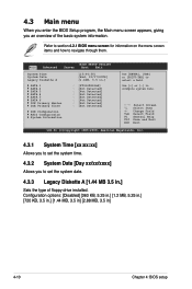
... system Date. ←→ Select Screen ↑↓ Select Item +- Change Field Tab Select Field F1 General Help F10 Save and Exit ESC Exit v02.61 (C)Copyright 1985-2008, American Megatrends, Inc. 4.3.1 System Time [xx:xx:xx] Allows you to set the system date. 4.3.3 Legacy Diskette A [1.44 MB 3.5 in.] ...Day xx/xx/xxxx] Allows you an overview of floppy drive installed. Use [+] or [-] to navigate through them. Main Advanced BIOS SETUP UTILITY Server Boot Exit System Time [13:44:30] System Date [Wed, 12/17/2008] Legacy Diskette A [1.44M, 3.5 in ] 4-10 Chapter 4: BIOS setup
... system Date. ←→ Select Screen ↑↓ Select Item +- Change Field Tab Select Field F1 General Help F10 Save and Exit ESC Exit v02.61 (C)Copyright 1985-2008, American Megatrends, Inc. 4.3.1 System Time [xx:xx:xx] Allows you to set the system date. 4.3.3 Legacy Diskette A [1.44 MB 3.5 in.] ...Day xx/xx/xxxx] Allows you an overview of floppy drive installed. Use [+] or [-] to navigate through them. Main Advanced BIOS SETUP UTILITY Server Boot Exit System Time [13:44:30] System Date [Wed, 12/17/2008] Legacy Diskette A [1.44M, 3.5 in ] 4-10 Chapter 4: BIOS setup
User Manual
Page 79
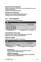
...AHCI mode need to the system. SATA Port0 [Auto] Allows you to the system. Main BIOS SETUP UTILITY AHCI Settings AHCI CD/DVD Boot Time out [35] SATA Port1 [Not Detected] SATA Port2 [Not Detected] SATA Port3 [Not Detected] SATA Port4 [Not Detected] ... Configuration options: [0] [5] [10] [15] [20] [25] [30] [35] 4.3.6 AHCI Configuration This menu is accessed through BIOS. Configuration options: [Disabled] [Enabled] ASUS Z8PE-D12 Series 4-13 Congifuration options: [0] [5] [10] [15] [20] [25] [30] [35] SATA Port1-6 [XXXX] Displays the status of auto-detection of SATA devices....
...AHCI mode need to the system. SATA Port0 [Auto] Allows you to the system. Main BIOS SETUP UTILITY AHCI Settings AHCI CD/DVD Boot Time out [35] SATA Port1 [Not Detected] SATA Port2 [Not Detected] SATA Port3 [Not Detected] SATA Port4 [Not Detected] ... Configuration options: [0] [5] [10] [15] [20] [25] [30] [35] 4.3.6 AHCI Configuration This menu is accessed through BIOS. Configuration options: [Disabled] [Enabled] ASUS Z8PE-D12 Series 4-13 Congifuration options: [0] [5] [10] [15] [20] [25] [30] [35] SATA Port1-6 [XXXX] Displays the status of auto-detection of SATA devices....

User Manual
Page 82
...] [Enabled] +F1 F10 ESC Select Screen Select Item Change Option General Help Save and Exit Exit v02.61 (C)Copyright 1985-2008, American Megatrends, Inc. 4-16 Chapter 4: BIOS setup Main Advanced Server BIOS SETUP UTILITY Boot Exit CPU Configuration Chipset Configuration Legacy Device Configuration USB Configuration PCIPnP Configuration Power On Configuration Event Log...
...] [Enabled] +F1 F10 ESC Select Screen Select Item Change Option General Help Save and Exit Exit v02.61 (C)Copyright 1985-2008, American Megatrends, Inc. 4-16 Chapter 4: BIOS setup Main Advanced Server BIOS SETUP UTILITY Boot Exit CPU Configuration Chipset Configuration Legacy Device Configuration USB Configuration PCIPnP Configuration Power On Configuration Event Log...
User Manual
Page 92
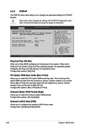
... Option ROM Priority [High] Allows you to configure the onboard LAN1/2 boot mode. Configuration options: [Normal] [High] Onboard LAN1/2 Boot [PXE] Allows you to select the onboard option ROM priority. The ...and Play operating system, the operating system configures the Plug and Play devices not required for boot if your system has a Plug and Play operating system. ←→ Select Screen &#...Scan Order [Bus 0 First] Onboard Option ROM Priority [High] Onboard LAN1 Boot [PXE] Onboard LAN2 Boot [PXE] NO: lets the BIOS configure all the devices in below sections may...
... Option ROM Priority [High] Allows you to configure the onboard LAN1/2 boot mode. Configuration options: [Normal] [High] Onboard LAN1/2 Boot [PXE] Allows you to select the onboard option ROM priority. The ...and Play operating system, the operating system configures the Plug and Play devices not required for boot if your system has a Plug and Play operating system. ←→ Select Screen &#...Scan Order [Bus 0 First] Onboard Option ROM Priority [High] Onboard LAN1 Boot [PXE] Onboard LAN2 Boot [PXE] NO: lets the BIOS configure all the devices in below sections may...
User Manual
Page 99
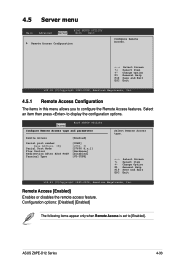
...Select Item +- Change Option F1 General Help F10 Save and Exit ESC Exit v02.61 (C)Copyright 1985-2008, American Megatrends, Inc. ASUS Z8PE-D12 Series 4-33 4.5 Server menu Main Advanced Server BIOS SETUP UTILITY Boot Exit Remote Access Configuration Configure Remote Access. ←→ Select Screen ↑↓...when Remote Access is set to display the configuration options. Change Option F1 General Help F10 Save and Exit ESC Exit v02.61 (C)Copyright 1985-2008, American Megatrends, Inc. 4.5.1 Remote Access Configuration The items in this menu allows you to configure the ...
...Select Item +- Change Option F1 General Help F10 Save and Exit ESC Exit v02.61 (C)Copyright 1985-2008, American Megatrends, Inc. ASUS Z8PE-D12 Series 4-33 4.5 Server menu Main Advanced Server BIOS SETUP UTILITY Boot Exit Remote Access Configuration Configure Remote Access. ←→ Select Screen ↑↓...when Remote Access is set to display the configuration options. Change Option F1 General Help F10 Save and Exit ESC Exit v02.61 (C)Copyright 1985-2008, American Megatrends, Inc. 4.5.1 Remote Access Configuration The items in this menu allows you to configure the ...
User Manual
Page 100
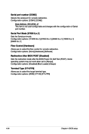
Some operating system may not work when set to select the target terminal type. Configuration options: [Disabled] [Boot Loader] [Always] Terminal Type [VT-UTF8] Allows you to select the flow control for console redirection. Serial Port Mode [57600 8,n,1] Sets the Serial port mode. ...
Some operating system may not work when set to select the target terminal type. Configuration options: [Disabled] [Boot Loader] [Always] Terminal Type [VT-UTF8] Allows you to select the flow control for console redirection. Serial Port Mode [57600 8,n,1] Sets the Serial port mode. ...
User Manual
Page 101
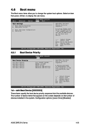
...Disabled] ASUS Z8PE-D12 Series 4-35 Select an item then press to display the sub-menu. A virtual floppy disk drive (Floppy Drive B: ) may appear when you to change the system boot options. A device enclosed in parenthesis has been disabled in the system. 4.6 Boot menu The Boot menu...F1 General Help F10 Save and Exit ESC Exit v02.61 (C)Copyright 1985-2008, American Megatrends, Inc. 4.6.1 Boot Device Priority BIOS SETUP UTILITY Boot Boot Device Priority 1st Boot Device 2nd Boot Device 3rd Boot Device 4th Boot Device 5th Boot Device [1st FLOPPY DRIVE] [ATAPI CD-ROM] [...
...Disabled] ASUS Z8PE-D12 Series 4-35 Select an item then press to display the sub-menu. A virtual floppy disk drive (Floppy Drive B: ) may appear when you to change the system boot options. A device enclosed in parenthesis has been disabled in the system. 4.6 Boot menu The Boot menu...F1 General Help F10 Save and Exit ESC Exit v02.61 (C)Copyright 1985-2008, American Megatrends, Inc. 4.6.1 Boot Device Priority BIOS SETUP UTILITY Boot Boot Device Priority 1st Boot Device 2nd Boot Device 3rd Boot Device 4th Boot Device 5th Boot Device [1st FLOPPY DRIVE] [ATAPI CD-ROM] [...

User Manual
Page 102
...Exit v02.61 (C)Copyright 1985-2008, American Megatrends, Inc. This will decrease the time needed to enable or disable the full screen logo display feature. Configuration options: [1st FLOPPY DRIVE] [Disabled] 4.6.3 Boot Settings Configuration BIOS SETUP UTILITY Boot Boot Settings Configuration Quick Boot Full ... to skip some power on self tests (POST) while booting to decrease the time needed to use the ASUS MyLogo2™ feature. 4-36 Chapter 4: BIOS setup Quick Boot [Enabled] Enabling this item to [Enabled] to boot the system. ←→ Select Screen ↑↓...
...Exit v02.61 (C)Copyright 1985-2008, American Megatrends, Inc. This will decrease the time needed to enable or disable the full screen logo display feature. Configuration options: [1st FLOPPY DRIVE] [Disabled] 4.6.3 Boot Settings Configuration BIOS SETUP UTILITY Boot Boot Settings Configuration Quick Boot Full ... to skip some power on self tests (POST) while booting to decrease the time needed to use the ASUS MyLogo2™ feature. 4-36 Chapter 4: BIOS setup Quick Boot [Enabled] Enabling this item to [Enabled] to boot the system. ←→ Select Screen ↑↓...

User Manual
Page 104
... Security The Security menu items allow you can clear it by erasing the CMOS Real Time Clock (RTC) RAM. BIOS SETUP UTILITY Boot Security Settings Supervisor Password : Not Installed User Password : Not Installed to disable password. The Supervisor Password item on how to change the... Password Change User Password ←→ Select Screen ↑↓ Select Item Enter Change F1 General Help F10 Save and Exit ESC Exit v02.61 (C)Copyright 1985-2008, American Megatrends, Inc. After you successfully set your BIOS password, you to erase the RTC RAM. 4-38 Chapter 4: BIOS...
... Security The Security menu items allow you can clear it by erasing the CMOS Real Time Clock (RTC) RAM. BIOS SETUP UTILITY Boot Security Settings Supervisor Password : Not Installed User Password : Not Installed to disable password. The Supervisor Password item on how to change the... Password Change User Password ←→ Select Screen ↑↓ Select Item Enter Change F1 General Help F10 Save and Exit ESC Exit v02.61 (C)Copyright 1985-2008, American Megatrends, Inc. After you successfully set your BIOS password, you to erase the RTC RAM. 4-38 Chapter 4: BIOS...

User Manual
Page 105
...supervisor password, the other items appear to allow change password. Main Advanced BIOS SETUP UTILITY Server Power Boot Tools Exit Supervisor Password : Installed User Password : Not Installed Change Supervisor Password User Access Level Change...setting a user password. To set to [Setup], BIOS checks for user password both when accessing Setup and booting the system. User Access Level [Full Access] This item allows you set your password successfully. Limited allows ... and/or numbers, then press . 3. Configuration options: [Setup] [Always] ASUS Z8PE-D12 Series 4-39
...supervisor password, the other items appear to allow change password. Main Advanced BIOS SETUP UTILITY Server Power Boot Tools Exit Supervisor Password : Installed User Password : Not Installed Change Supervisor Password User Access Level Change...setting a user password. To set to [Setup], BIOS checks for user password both when accessing Setup and booting the system. User Access Level [Full Access] This item allows you set your password successfully. Limited allows ... and/or numbers, then press . 3. Configuration options: [Setup] [Always] ASUS Z8PE-D12 Series 4-39


