
User Manual
Page 4
... 3.1 Starting up for the first time 3-1 3.2 Turning off the computer 3-2 3.2.1 Using the OS shut down function 3-2 3.2.2 Using the dual function power switch 3-2 Chapter 4 BIOS setup 4.1 Managing and updating your BIOS 4-1 4.1.1 AFUDOS utility 4-1 4.1.2 ASUS CrashFree BIOS 3 utility 4-3 4.2 BIOS setup program 4-4 4.2.1 BIOS menu screen 4-5 4.2.2 Menu bar 4-5 4.2.3 Navigation keys 4-5 4.2.4 Menu items 4-6 4.2.5 Sub-menu items 4-6 4.2.6 Configuration...
... 3.1 Starting up for the first time 3-1 3.2 Turning off the computer 3-2 3.2.1 Using the OS shut down function 3-2 3.2.2 Using the dual function power switch 3-2 Chapter 4 BIOS setup 4.1 Managing and updating your BIOS 4-1 4.1.1 AFUDOS utility 4-1 4.1.2 ASUS CrashFree BIOS 3 utility 4-3 4.2 BIOS setup program 4-4 4.2.1 BIOS menu screen 4-5 4.2.2 Menu bar 4-5 4.2.3 Navigation keys 4-5 4.2.4 Menu items 4-6 4.2.5 Sub-menu items 4-6 4.2.6 Configuration...

User Manual
Page 5
Contents 4.4 Advanced menu 4-13 4.4.1 CPU Configuration 4-13 4.4.2 Chipset Configuration 4-16 4.4.3 Legacy Device Configuration 4-20 4.4.4 USB Configuration 4-20 4.4.5 PCIPnP 4-21 4.4.6 Power On Configuration 4-22 4.4.7 Event Log Configuration 4-23 4.4.8 Hardware Monitor 4-24 4.4.9 ACPI Configuration 4-25 4.4.10 PCI Express Configuration 4-26 4.5 Server menu 4-27 4.6 Boot menu 4-29 4.6.1 Boot ...
Contents 4.4 Advanced menu 4-13 4.4.1 CPU Configuration 4-13 4.4.2 Chipset Configuration 4-16 4.4.3 Legacy Device Configuration 4-20 4.4.4 USB Configuration 4-20 4.4.5 PCIPnP 4-21 4.4.6 Power On Configuration 4-22 4.4.7 Event Log Configuration 4-23 4.4.8 Hardware Monitor 4-24 4.4.9 ACPI Configuration 4-25 4.4.10 PCI Express Configuration 4-26 4.5 Server menu 4-27 4.6 Boot menu 4-29 4.6.1 Boot ...
User Manual
Page 8
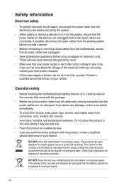
.... If you add a device. • Before connecting or removing signal cables from the motherboard, ensure that the power cables for disposal of parts and recycling. DO NOT throw the motherboard in municipal waste. This product has been designed to enable proper reuse of electronic products.... Operation safety • Before installing the motherboard and adding devices on a stable surface. • If you are using, contact your local power company. • If the power supply is set to the correct voltage in municipal waste. DO NOT...
.... If you add a device. • Before connecting or removing signal cables from the motherboard, ensure that the power cables for disposal of parts and recycling. DO NOT throw the motherboard in municipal waste. This product has been designed to enable proper reuse of electronic products.... Operation safety • Before installing the motherboard and adding devices on a stable surface. • If you are using, contact your local power company. • If the power supply is set to the correct voltage in municipal waste. DO NOT...

User Manual
Page 9
... provided. • Chapter 5: RAID configuration This chapter provides instructions for setting up sequence and ways of the motherboard and the new technologies it supports. • Chapter 2: Hardware information This chapter lists the hardware setup procedures that...This appendix includes additional information that you need when installing and configuring the motherboard. ASUS websites The ASUS website provides updated information on the motherboard. • Chapter 3: Powering up This chapter describes the power up , creating, and configuring RAID sets using the available utilities. &#...
... provided. • Chapter 5: RAID configuration This chapter provides instructions for setting up sequence and ways of the motherboard and the new technologies it supports. • Chapter 2: Hardware information This chapter lists the hardware setup procedures that...This appendix includes additional information that you need when installing and configuring the motherboard. ASUS websites The ASUS website provides updated information on the motherboard. • Chapter 3: Powering up This chapter describes the power up , creating, and configuring RAID sets using the available utilities. &#...

User Manual
Page 12
xii Z8NR-D12 specifications summary Networking Graphic Onboard I/O Connectors Rear I/O Connectors Management Solution ...Mouse Software Out of Band Remote Management CPU Temperature FAN RPM 2 x Intel® 82574L + 1 x Management LAN Aspeed AST2050 8MB 24-pin ATX power connector + 2 x 8-pin ATX 12V power connector 3 (support 4 USB ports and 1 internal Type A USB connector) 8 * 4Pin (With PWM control) 2 1 2 1 1 2 ...% ~ 90% (Non condensing) LSI® MegaRAID 5 function is available only when you install an ASUS PIKE RAID card with iBTN. *Specifications are subject to change without notice.
xii Z8NR-D12 specifications summary Networking Graphic Onboard I/O Connectors Rear I/O Connectors Management Solution ...Mouse Software Out of Band Remote Management CPU Temperature FAN RPM 2 x Intel® 82574L + 1 x Management LAN Aspeed AST2050 8MB 24-pin ATX power connector + 2 x 8-pin ATX 12V power connector 3 (support 4 USB ports and 1 internal Type A USB connector) 8 * 4Pin (With PWM control) 2 1 2 1 1 2 ...% ~ 90% (Non condensing) LSI® MegaRAID 5 function is available only when you install an ASUS PIKE RAID card with iBTN. *Specifications are subject to change without notice.

User Manual
Page 16
...ASUS Technical Support team members can then offer a quicker and satisfying solution to your problems. Z8NR-D12 xxM0Axxxxxxx Made in China 合格 1.4 Special features 1.4.1 Product highlights Latest processor technology This motherboard supports the latest Intel Xeon 5500 series processors in the world. This voltage reduction limits the power...memory is reduced from the ASUS Technical Support team, you must take note of the motherboard's serial number containing 12 characters xxM0Axxxxxxx shown as the CPU temperature is the one of the most powerful and energy-efficient CPUs in...
...ASUS Technical Support team members can then offer a quicker and satisfying solution to your problems. Z8NR-D12 xxM0Axxxxxxx Made in China 合格 1.4 Special features 1.4.1 Product highlights Latest processor technology This motherboard supports the latest Intel Xeon 5500 series processors in the world. This voltage reduction limits the power...memory is reduced from the ASUS Technical Support team, you must take note of the motherboard's serial number containing 12 characters xxM0Axxxxxxx shown as the CPU temperature is the one of the most powerful and energy-efficient CPUs in...

User Manual
Page 17
...Intel® EM64T feature allows your computer to PCIe 1.0 devices. 82574L LAN Solution The motherboard comes with a host of new features, including Native Command Queuing (NCQ), Power Management (PM) Implementation Algorithm, and Hot Swap. Enhanced Intel SpeedStep Technology (EIST) The...total solution for faster and more flexible cables with USB 1.1. ASUS Z8NR-D12 1-3 The Serial ATA II specification provides twice the bandwidth of system memory for your networking needs. USB 2.0 technology The motherboard implements the Universal Serial Bus (USB) 2.0 specification, dramatically ...
...Intel® EM64T feature allows your computer to PCIe 1.0 devices. 82574L LAN Solution The motherboard comes with a host of new features, including Native Command Queuing (NCQ), Power Management (PM) Implementation Algorithm, and Hot Swap. Enhanced Intel SpeedStep Technology (EIST) The...total solution for faster and more flexible cables with USB 1.1. ASUS Z8NR-D12 1-3 The Serial ATA II specification provides twice the bandwidth of system memory for your networking needs. USB 2.0 technology The motherboard implements the Universal Serial Bus (USB) 2.0 specification, dramatically ...

User Manual
Page 18
... different segments and purposes and PIKE saves lots of current for critical components. 1.4.2 Innovative ASUS features ASUS EPU With current trends leaning towards power efficiency, the Z8NR-D12 is an on the Slot 6. PIKE (Proprietary I/O Kit Expansion) PIKE is equipped with the ASUS exclusive EPU technology to choose their preferred I /O solutions without occupying the Slot 6 in...
... different segments and purposes and PIKE saves lots of current for critical components. 1.4.2 Innovative ASUS features ASUS EPU With current trends leaning towards power efficiency, the Z8NR-D12 is an on the Slot 6. PIKE (Proprietary I/O Kit Expansion) PIKE is equipped with the ASUS exclusive EPU technology to choose their preferred I /O solutions without occupying the Slot 6 in...

User Manual
Page 21
ASUS Z8NR-D12 2-1 2.1 Before you proceed Take note of the following precautions before you install or remove any component, ensure that came with the component. • Before you install motherboard components or change any motherboard settings. • Unplug the power cord from the wall socket before handling components to avoid damaging them due to static electricity. •...
ASUS Z8NR-D12 2-1 2.1 Before you proceed Take note of the following precautions before you install or remove any component, ensure that came with the component. • Before you install motherboard components or change any motherboard settings. • Unplug the power cord from the wall socket before handling components to avoid damaging them due to static electricity. •...

User Manual
Page 22
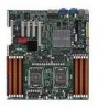
... motherboard. Doing so can cause you physical injury and damage motherboard components! 2.2.1 Placement direction When installing the motherboard, ensure that the motherboard fits into the holes indicated by circles to secure the motherboard to the chassis. 2.2 Motherboard overview Before you install the motherboard, study the configuration of your chassis to ensure that you place it in an SSI EEB...
... motherboard. Doing so can cause you physical injury and damage motherboard components! 2.2.1 Placement direction When installing the motherboard, ensure that the motherboard fits into the holes indicated by circles to secure the motherboard to the chassis. 2.2 Motherboard overview Before you install the motherboard, study the configuration of your chassis to ensure that you place it in an SSI EEB...

User Manual
Page 25
... connectors (10-1 pin COM2) 10. Serial ATA connectors (7-pin SATA1-4 [red], SATA5-6 [black]) 3. CPU and system fan connectors (4-pin CPU_FAN1/2, REAR_FAN1/2, FRNT_FAN1/2/3/4) 9. SSI power connectors (24-pin ATXPWR1, 8-pin ATX12V1/2) 12. Hard disk activity LED connector (4-pin HDLED1) 5. Baseboard Management Controller (BMC) connector (14-pin BMC_FW1) 13. Internal connectors...6. Auxiliary panel connector (20-pin AUX_PANEL1 [black]) Page 2-24 2-24 2-25 2-25 2-26 2-26 2-27 2-27 2-28 2-28 2-29 2-29 2-30 2-31 ASUS Z8NR-D12 2-5 Power supply SMBus connector (5-pin PSUSMB1) 11.
... connectors (10-1 pin COM2) 10. Serial ATA connectors (7-pin SATA1-4 [red], SATA5-6 [black]) 3. CPU and system fan connectors (4-pin CPU_FAN1/2, REAR_FAN1/2, FRNT_FAN1/2/3/4) 9. SSI power connectors (24-pin ATXPWR1, 8-pin ATX12V1/2) 12. Hard disk activity LED connector (4-pin HDLED1) 5. Baseboard Management Controller (BMC) connector (14-pin BMC_FW1) 13. Internal connectors...6. Auxiliary panel connector (20-pin AUX_PANEL1 [black]) Page 2-24 2-24 2-25 2-25 2-26 2-26 2-27 2-27 2-28 2-28 2-29 2-29 2-30 2-31 ASUS Z8NR-D12 2-5 Power supply SMBus connector (5-pin PSUSMB1) 11.

User Manual
Page 33
...Ensure to both the motherboard and the components. 1. Align a DIMM on the socket such that it flips out with extra force. 2. The DIMM might get damaged when it fits in place and the DIMM is keyed with your fingers when pressing the retaining clips. ASUS Z8NR-D12 2-13 Failure to do... so may cause severe damage to unplug the power supply before adding or removing DIMMs or other system components. Locked Retaining Clip 2.4.4 Removing a DIMM ...
...Ensure to both the motherboard and the components. 1. Align a DIMM on the socket such that it flips out with extra force. 2. The DIMM might get damaged when it fits in place and the DIMM is keyed with your fingers when pressing the retaining clips. ASUS Z8NR-D12 2-13 Failure to do... so may cause severe damage to unplug the power supply before adding or removing DIMMs or other system components. Locked Retaining Clip 2.4.4 Removing a DIMM ...

User Manual
Page 34
...if any. See Chapter 4 for the expansion card. 2-14 Chapter 2: Hardware information 2.5 Expansion slots In the future, you physical injury and damage motherboard components. 2.5.1 Installing an expansion card To install an expansion card: 1. Refer to install expansion cards. Ensure to the card. Turn on the ...next page. 3. Assign an IRQ to unplug the power cord before adding or removing expansion cards. The following sub‑sections describe the slots and the expansion cards that you removed earlier....
...if any. See Chapter 4 for the expansion card. 2-14 Chapter 2: Hardware information 2.5 Expansion slots In the future, you physical injury and damage motherboard components. 2.5.1 Installing an expansion card To install an expansion card: 1. Refer to install expansion cards. Ensure to the card. Turn on the ...next page. 3. Assign an IRQ to unplug the power cord before adding or removing expansion cards. The following sub‑sections describe the slots and the expansion cards that you removed earlier....

User Manual
Page 38
The onboard button cell battery powers the RAM data in CMOS. Clear RTC RAM (CLRTC1) This jumper allows you to pins 1-2. 3. Keep the cap on CLRTC jumper default position. If the ... 2-3. 2.6 Jumpers 1. Removing the cap will cause system boot failure! Move the jumper cap from pins 1-2 (default) to clear the CMOS RTC RAM data. Plug the power cord and turn ON the computer. 4. To erase the RTC RAM: 1. Hold down the key during the boot process and enter BIOS setup to re...
The onboard button cell battery powers the RAM data in CMOS. Clear RTC RAM (CLRTC1) This jumper allows you to pins 1-2. 3. Keep the cap on CLRTC jumper default position. If the ... 2-3. 2.6 Jumpers 1. Removing the cap will cause system boot failure! Move the jumper cap from pins 1-2 (default) to clear the CMOS RTC RAM data. Plug the power cord and turn ON the computer. 4. To erase the RTC RAM: 1. Hold down the key during the boot process and enter BIOS setup to re...

User Manual
Page 48
Power supply SMBus connector (5-pin PSUSMB1) This connector is for a serial (COM) port. Serial port connector (10-1 pin COM2) This connector is purchased separately. 10. 9. Connect the serial port module cable to this connector, then install the module to a slot opening at the back of the system chassis. The serial port module is for the power supply SMB cable, if your power supply supports the SMBus function. 2-28 Chapter 2: Hardware information
Power supply SMBus connector (5-pin PSUSMB1) This connector is for a serial (COM) port. Serial port connector (10-1 pin COM2) This connector is purchased separately. 10. 9. Connect the serial port module cable to this connector, then install the module to a slot opening at the back of the system chassis. The serial port module is for the power supply SMB cable, if your power supply supports the SMBus function. 2-28 Chapter 2: Hardware information

User Manual
Page 49
... that you intend to connect the 24+8+8-pin power plugs; The ASMB4 management device is recommended when configuring a system with a higher power rating if you use an SSI 12 V-compliant power supply unit (PSU) for SSI power supply plugs. 11. otherwise, the system will... not boot up if the power is an interface used to fit these connectors in an ASMB4-SOL or ASMB4-iKVM management device. The system may become unstable or may not boot up . • Use of a PSU with a higher power output is purchased separately. ASUS Z8NR-D12...
... that you intend to connect the 24+8+8-pin power plugs; The ASMB4 management device is recommended when configuring a system with a higher power rating if you use an SSI 12 V-compliant power supply unit (PSU) for SSI power supply plugs. 11. otherwise, the system will... not boot up if the power is an interface used to fit these connectors in an ASMB4-SOL or ASMB4-iKVM management device. The system may become unstable or may not boot up . • Use of a PSU with a higher power output is purchased separately. ASUS Z8NR-D12...

User Manual
Page 50
... settings. The IDE LED lights up when you to indicate an abnormal event occurance. 3. Pressing the power button turns the system on or puts the system in sleep mode. 2. Pressing the power switch for the chassis-mounted system warning speaker. System panel connector (20-pin PANEL1 [white]) This ...This 2-pin connector is for the chassis-mounted reset button for system reboot without turning off mode depending on the system power, and blinks when the system is for the system power LED. ATX power button/soft-off button (2-pin PWRSW) This connector is in sleep or soft-off the system...
... settings. The IDE LED lights up when you to indicate an abnormal event occurance. 3. Pressing the power button turns the system on or puts the system in sleep mode. 2. Pressing the power switch for the chassis-mounted system warning speaker. System panel connector (20-pin PANEL1 [white]) This ...This 2-pin connector is for the chassis-mounted reset button for system reboot without turning off mode depending on the system power, and blinks when the system is for the system power LED. ATX power button/soft-off button (2-pin PWRSW) This connector is in sleep or soft-off the system...

User Manual
Page 53
This chapter describes the power up Powerin3g up sequence, and ways of shutting down the system.
This chapter describes the power up Powerin3g up sequence, and ways of shutting down the system.

User Manual
Page 55
...three short beeps One continuous beep followed by four short beeps Description VGA detected Quick boot set to the power connector at the back of the system chassis. 4. Connect the power cord to enter the BIOS Setup. Turn on the system front panel case lights up when you press the... up or switch between orange and green after the system LED turns on test. Follow the instructions in the following order: a. Monitor b. System power 6. ASUS Z8NR-D12 3-1 After making all switches are running, the BIOS beeps (see anything within 30 seconds from the time you do not see BIOS beep codes ...
...three short beeps One continuous beep followed by four short beeps Description VGA detected Quick boot set to the power connector at the back of the system chassis. 4. Connect the power cord to enter the BIOS Setup. Turn on the system front panel case lights up when you press the... up or switch between orange and green after the system LED turns on test. Follow the instructions in the following order: a. Monitor b. System power 6. ASUS Z8NR-D12 3-1 After making all switches are running, the BIOS beeps (see anything within 30 seconds from the time you do not see BIOS beep codes ...

User Manual
Page 56
... 3.2.1 Using the OS shut down the computer. 3. Click the Start button then select Turn Off Computer. 2. The power supply should turn off mode regardless of the BIOS setting. 3-2 Chapter 3: Powering up If you are using Windows® 2003: 1. Click the Start button then click Shut Down... 2. Ensure that...174; shuts down the computer. 3. Click the Turn Off button to soft-off after Windows® shuts down. 3.2.2 Using the dual function power switch While the system is selected, then click the OK button to shut down function If you are using Windows® XP: 1. The...
... 3.2.1 Using the OS shut down the computer. 3. Click the Start button then select Turn Off Computer. 2. The power supply should turn off mode regardless of the BIOS setting. 3-2 Chapter 3: Powering up If you are using Windows® 2003: 1. Click the Start button then click Shut Down... 2. Ensure that...174; shuts down the computer. 3. Click the Turn Off button to soft-off after Windows® shuts down. 3.2.2 Using the dual function power switch While the system is selected, then click the OK button to shut down function If you are using Windows® XP: 1. The...


