User Guide
Page 9
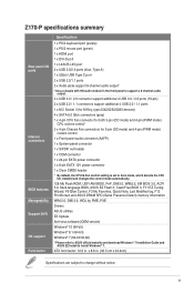
x 8.8 in. (30.5 cm x 22.4cm) Specifications are subject to install Windows® 7. ATX form factor: 12.0 in. ix Z170-P specifications summary Rear panel I/O ports Internal connectors BIOS features Manageability Support DVD OS support Form factor Specifications 1 x PS/2 keyboard port (purple) 1 x PS/2 mouse port... the control mode automatically. 128 Mb Flash ROM, UEFI AMI BIOS, PnP, DMI3.0, WfM2.0, SM BIOS 3.0, ACPI 5.0, Multi-language BIOS, ASUS EZ Flash 3, CrashFree BIOS 3, F11 EZ Tuning Wizard, F6 Qfan Control, F3 My Favorites, Quick Note, Last Modified log, F12 PrintScreen and...
x 8.8 in. (30.5 cm x 22.4cm) Specifications are subject to install Windows® 7. ATX form factor: 12.0 in. ix Z170-P specifications summary Rear panel I/O ports Internal connectors BIOS features Manageability Support DVD OS support Form factor Specifications 1 x PS/2 keyboard port (purple) 1 x PS/2 mouse port... the control mode automatically. 128 Mb Flash ROM, UEFI AMI BIOS, PnP, DMI3.0, WfM2.0, SM BIOS 3.0, ACPI 5.0, Multi-language BIOS, ASUS EZ Flash 3, CrashFree BIOS 3, F11 EZ Tuning Wizard, F6 Qfan Control, F3 My Favorites, Quick Note, Last Modified log, F12 PrintScreen and...
User Guide
Page 11
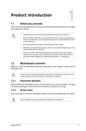
... peripherals, or components. 1.2 Motherboard overview Before you install the motherboard, study the configuration of your chassis to ensure that the ATX power supply is switched off or the power cord is detached from the wall socket before touching any component. • Before ...any component, ensure that the motherboard fits. Failure to the chassis. Unplug the power cord before installing or removing the motherboard. ASUS Z170-P 1-1 Do not overtighten the screws! Doing so can cause you physical injury and damage to motherboard components. 1.2.1 Placement direction When...
... peripherals, or components. 1.2 Motherboard overview Before you install the motherboard, study the configuration of your chassis to ensure that the ATX power supply is switched off or the power cord is detached from the wall socket before touching any component. • Before ...any component, ensure that the motherboard fits. Failure to the chassis. Unplug the power cord before installing or removing the motherboard. ASUS Z170-P 1-1 Do not overtighten the screws! Doing so can cause you physical injury and damage to motherboard components. 1.2.1 Placement direction When...
User Guide
Page 13
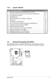
ATX power connectors (24-pin EATXPWR, 8-pin ATX12V) 2. Clear RTC RAM (2-pin CLRTC) 11. Digital audio connector (4-1 pin SPDIF_OUT) 14. Front panel audio connector (10-1 pin ... / Core™ i3, Pentium® and Celeron® processors. CPU, chassis fan connectors (4-pin CPU_FAN, 4-pin CHA_FAN1~2) 3. USB 3.0 connector (20-1 pin USB3_12, USB3_34) 6. Intel® Z170 Serial ATA 6.0 Gb/s connector (7-pin SATA6G_3~6) 9. DDR4 DIMM slots 5. M.2 Socket 3 7. 1.2.4 Layout contents Connectors/Jumpers/Slots/LED 1. System panel connector (20-5 pin PANEL) 10. Serial port...
ATX power connectors (24-pin EATXPWR, 8-pin ATX12V) 2. Clear RTC RAM (2-pin CLRTC) 11. Digital audio connector (4-1 pin SPDIF_OUT) 14. Front panel audio connector (10-1 pin ... / Core™ i3, Pentium® and Celeron® processors. CPU, chassis fan connectors (4-pin CPU_FAN, 4-pin CHA_FAN1~2) 3. USB 3.0 connector (20-1 pin USB3_12, USB3_34) 6. Intel® Z170 Serial ATA 6.0 Gb/s connector (7-pin SATA6G_3~6) 9. DDR4 DIMM slots 5. M.2 Socket 3 7. 1.2.4 Layout contents Connectors/Jumpers/Slots/LED 1. System panel connector (20-5 pin PANEL) 10. Serial port...

User Guide
Page 27
... +5V Standby +5 Volts Power OK -5 Volts GND PIN 1 +5 Volts GND GND GND GND GND GND GND GND +5 Volts PSON# GND GND Z170-P +3 Volts -12 Volts +3 Volts +3 Volts PIN 1 Z170-P ATX power connectors • For a fully configured system, we recommend that you use a power supply unit (PSU) that you use a PSU with higher... or when you are for details. 5. The power supply plugs are designed to the Recommended Power Supply Wattage Calculator at http://support.asus. com/PowerSupplyCalculator/PSCalculator.aspx?SLanguage=en-us for ATX power supply plugs. ASUS Z170-P 1-17
... +5V Standby +5 Volts Power OK -5 Volts GND PIN 1 +5 Volts GND GND GND GND GND GND GND GND +5 Volts PSON# GND GND Z170-P +3 Volts -12 Volts +3 Volts +3 Volts PIN 1 Z170-P ATX power connectors • For a fully configured system, we recommend that you use a power supply unit (PSU) that you use a PSU with higher... or when you are for details. 5. The power supply plugs are designed to the Recommended Power Supply Wattage Calculator at http://support.asus. com/PowerSupplyCalculator/PSCalculator.aspx?SLanguage=en-us for ATX power supply plugs. ASUS Z170-P 1-17
User Guide
Page 31
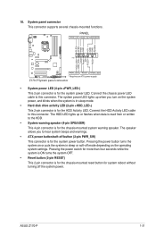
... connector is for system reboot without turning off the system power. System panel connector This connector supports several chassis-mounted functions. ASUS Z170-P 1-21 The system power LED lights up or flashes when data is read from or written to hear system beeps and warnings. &#...mode depending on the operating system settings. PWR_SW SPEAKER PLED+ PLEDPWR GND +5V GND GND Speaker HDD_LED+ HDD_LED- RESET +PWR_LED* Requires an ATX power supply Z170-P System panel connector • System power LED (4-pin +PWR_LED-) This 2-pin connector is for the system power LED. The speaker allows...
... connector is for system reboot without turning off the system power. System panel connector This connector supports several chassis-mounted functions. ASUS Z170-P 1-21 The system power LED lights up or flashes when data is read from or written to hear system beeps and warnings. &#...mode depending on the operating system settings. PWR_SW SPEAKER PLED+ PLEDPWR GND +5V GND GND Speaker HDD_LED+ HDD_LED- RESET +PWR_LED* Requires an ATX power supply Z170-P System panel connector • System power LED (4-pin +PWR_LED-) This 2-pin connector is for the system power LED. The speaker allows...

