
User Guide
Page 1
Z170-A Motherboard
Z170-A Motherboard
User Guide
Page 3
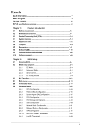
Contents Safety information...v About this guide...v Package contents...vii Z170-A specifications summary vii Chapter 1: Product Introduction 1.1 Before you proceed 1-1 1.2 Motherboard overview 1-1 1.3 Central Processing Unit (CPU 1-4 1.4 System memory 1-8 1.5 Expansion slots 1-16 1.6 Jumpers...1-19 1.7 Connectors 1-21 1.8 Onboard LEDs 1-34 1.9 Onboard buttons and switches 1-36 1.10 Software support 1-...
Contents Safety information...v About this guide...v Package contents...vii Z170-A specifications summary vii Chapter 1: Product Introduction 1.1 Before you proceed 1-1 1.2 Motherboard overview 1-1 1.3 Central Processing Unit (CPU 1-4 1.4 System memory 1-8 1.5 Expansion slots 1-16 1.6 Jumpers...1-19 1.7 Connectors 1-21 1.8 Onboard LEDs 1-34 1.9 Onboard buttons and switches 1-36 1.10 Software support 1-...
User Guide
Page 5
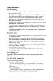
... stable surface. • If you detect any area where it may be exposed to moisture. • Place the product on the motherboard. • Chapter 2: BIOS Setup This chapter discusses changing system settings through the BIOS Setup menus. Contact a qualified service technician or your...v Detailed descriptions for the devices are unplugged before the signal cables are connected. If you need when installing and configuring the motherboard. About this guide is organized This guide contains the following parts: • Chapter 1: Product Introduction This chapter describes the ...
... stable surface. • If you detect any area where it may be exposed to moisture. • Place the product on the motherboard. • Chapter 2: BIOS Setup This chapter discusses changing system settings through the BIOS Setup menus. Contact a qualified service technician or your...v Detailed descriptions for the devices are unplugged before the signal cables are connected. If you need when installing and configuring the motherboard. About this guide is organized This guide contains the following parts: • Chapter 1: Product Introduction This chapter describes the ...

User Guide
Page 7
...Profile (XMP) Expansion Slots * Hyper DIMM support is damaged or missing, contact your retailer. Integrated Graphics Processor- Z170-A specifications summary LGA1151 socket for 6th Generation Intel® Core™ i7/ i5/ i3/Pentium®/Celeron®... Boost Technology 2.0 support depends on the next page) vii Package contents Check your motherboard package for the following items: Motherboard ASUS Z170-A Motherboard Cables 3 x Serial ATA 6.0 Gb/s cables 1 x ASUS SLI bridge connector Accessories 2-in-1 Q-connector M.2 screw package CPU installation tool Application DVD...
...Profile (XMP) Expansion Slots * Hyper DIMM support is damaged or missing, contact your retailer. Integrated Graphics Processor- Z170-A specifications summary LGA1151 socket for 6th Generation Intel® Core™ i7/ i5/ i3/Pentium®/Celeron®... Boost Technology 2.0 support depends on the next page) vii Package contents Check your motherboard package for the following items: Motherboard ASUS Z170-A Motherboard Cables 3 x Serial ATA 6.0 Gb/s cables 1 x ASUS SLI bridge connector Accessories 2-in-1 Q-connector M.2 screw package CPU installation tool Application DVD...
User Guide
Page 13
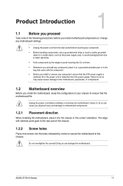
...power supply is switched off or the power cord is detached from the wall socket before installing or removing the motherboard. ASUS Z170-A Series 1-1 Failure to do so can damage the motherboard. Doing so can cause you physical injury and damage to avoid touching the ICs on a grounded antistatic pad ... object, such as the power supply case, to avoid damaging them due to static electricity. • Hold components by circles to secure the motherboard to the rear part of the chassis. 1.2.2 Screw holes Place nine screws into the chassis in the bag that came with the component. •...
...power supply is switched off or the power cord is detached from the wall socket before installing or removing the motherboard. ASUS Z170-A Series 1-1 Failure to do so can damage the motherboard. Doing so can cause you physical injury and damage to avoid touching the ICs on a grounded antistatic pad ... object, such as the power supply case, to avoid damaging them due to static electricity. • Hold components by circles to secure the motherboard to the rear part of the chassis. 1.2.2 Screw holes Place nine screws into the chassis in the bag that came with the component. •...

User Guide
Page 14
Place this side towards the rear of the chassis 1.2.3 Motherboard layout 1-2 Chapter 1: Product Introduction
Place this side towards the rear of the chassis 1.2.3 Motherboard layout 1-2 Chapter 1: Product Introduction

User Guide
Page 16
... other sockets on the LGA1151 socket. • Ensure that all power cables are not bent. ASUS will process Return Merchandise Authorization (RMA) requests only if the motherboard comes with a surface mount LGA1151 socket designed for LGA1151 socket only. ASUS will shoulder the cost of the PnP cap. 1-4 Chapter 1: Product Introduction 1.3 Central Processing Unit...
... other sockets on the LGA1151 socket. • Ensure that all power cables are not bent. ASUS will process Return Merchandise Authorization (RMA) requests only if the motherboard comes with a surface mount LGA1151 socket designed for LGA1151 socket only. ASUS will shoulder the cost of the PnP cap. 1-4 Chapter 1: Product Introduction 1.3 Central Processing Unit...
User Guide
Page 20
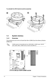
To uninstall the CPU heatsink and fan assembly 1.4 System memory 1.4.1 Overview The motherboard comes with four Double Data Rate 4 (DDR4) Dual Inline Memory Modules (DIMM) slots. DO NOT install a DDR, DDR2, or DDR3 memory module to the DDR4 slot. 1-8 Chapter 1: Product Introduction A DDR4 module is notched differently from a DDR, DDR2, or DDR3 module.
To uninstall the CPU heatsink and fan assembly 1.4 System memory 1.4.1 Overview The motherboard comes with four Double Data Rate 4 (DDR4) Dual Inline Memory Modules (DIMM) slots. DO NOT install a DDR, DDR2, or DDR3 memory module to the DDR4 slot. 1-8 Chapter 1: Product Introduction A DDR4 module is notched differently from a DDR, DDR2, or DDR3 module.
User Guide
Page 21
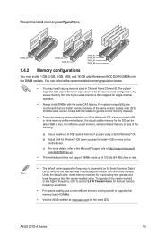
... of the lower-sized channel for manual memory frequency adjustment. • For system stability, use a more memory on the motherboard. ASUS Z170-A Series 1-9 com/kb/929605/en-us. • This motherboard does not support DIMMs made up of 512 Mb (64 MB) chips or less. • The default memory operation frequency...way of the same version or date code (D/C) from the higher-sized channel is then mapped for the latest QVL. c) For more on the motherboard, the actual usable memory for overclocking may install 1 GB, 2 GB, 4 GB, 8GB, and 16 GB unbuffered non-ECC DDR4 DIMMs into ...
... of the lower-sized channel for manual memory frequency adjustment. • For system stability, use a more memory on the motherboard. ASUS Z170-A Series 1-9 com/kb/929605/en-us. • This motherboard does not support DIMMs made up of 512 Mb (64 MB) chips or less. • The default memory operation frequency...way of the same version or date code (D/C) from the higher-sized channel is then mapped for the latest QVL. c) For more on the motherboard, the actual usable memory for overclocking may install 1 GB, 2 GB, 4 GB, 8GB, and 16 GB unbuffered non-ECC DDR4 DIMMs into ...
User Guide
Page 22
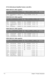
... (Optional) 1 2 4 • • 1.35V • • 1.35V • • 1.35V • 1.35V • 1.35V • 1.35V • 1.35V • 1.35V • 1-10 Chapter 1: Product Introduction Z170-A Motherboard Qualified Vendors Lists (QVL) DDR4 3400 (O.C.) MHz capability Vendors Part No. Timing SK Hynix H5AN4G8NMFR 16-16-16-36 Samsung K4A4G085WD 16-18-18-38...
... (Optional) 1 2 4 • • 1.35V • • 1.35V • • 1.35V • 1.35V • 1.35V • 1.35V • 1.35V • 1.35V • 1-10 Chapter 1: Product Introduction Z170-A Motherboard Qualified Vendors Lists (QVL) DDR4 3400 (O.C.) MHz capability Vendors Part No. Timing SK Hynix H5AN4G8NMFR 16-16-16-36 Samsung K4A4G085WD 16-18-18-38...
User Guide
Page 28
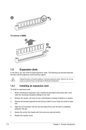
... chassis with the screw you removed earlier. 6. Remove the bracket opposite the slot that they support. Remove the system unit cover (if your motherboard is completely seated on the slot. 5. Keep the screw for the card. 2. Align the card connector with it and make the necessary hardware ... adding or removing expansion cards. To remove a DIMM 1.5 Expansion slots In the future, you may cause you physical injury and damage motherboard components. 1.5.1 Installing an expansion card To install an expansion card: 1. Replace the system cover. 1-16 Chapter 1: Product Introduction
... chassis with the screw you removed earlier. 6. Remove the bracket opposite the slot that they support. Remove the system unit cover (if your motherboard is completely seated on the slot. 5. Keep the screw for the card. 2. Align the card connector with it and make the necessary hardware ... adding or removing expansion cards. To remove a DIMM 1.5 Expansion slots In the future, you may cause you physical injury and damage motherboard components. 1.5.1 Installing an expansion card To install an expansion card: 1. Replace the system cover. 1-16 Chapter 1: Product Introduction
User Guide
Page 29
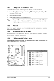
...slot PCIe 3.0/2.0 x1_1 slot PCIe 3.0/2.0 x16_1 slot PCIe 3.0/2.0 x1_2 slot PCI slot PCIe 3.0/2.0 x16_2 slot PCIe 3.0/2.0 x1_3 slot PCIe 3.0/2.0 x16_3 slot ASUS Z170-A Series 1-17 Install the software drivers for information on BIOS setup. 2. See Chapter 2 for the expansion card. Assign an IRQ to the card... card, SCSI card, USB card, and other cards that comply with PCI specifications. 1.5.4 PCI Express 3.0 / 2.0 x1 slots This motherboard supports PCI Express x1 network cards, SCSI cards, and other cards that comply with the PCI Express specifications. 1.5.5 PCI Express 3.0 / 2.0 x16...
...slot PCIe 3.0/2.0 x1_1 slot PCIe 3.0/2.0 x16_1 slot PCIe 3.0/2.0 x1_2 slot PCI slot PCIe 3.0/2.0 x16_2 slot PCIe 3.0/2.0 x1_3 slot PCIe 3.0/2.0 x16_3 slot ASUS Z170-A Series 1-17 Install the software drivers for information on BIOS setup. 2. See Chapter 2 for the expansion card. Assign an IRQ to the card... card, SCSI card, USB card, and other cards that comply with PCI specifications. 1.5.4 PCI Express 3.0 / 2.0 x1 slots This motherboard supports PCI Express x1 network cards, SCSI cards, and other cards that comply with the PCI Express specifications. 1.5.5 PCI Express 3.0 / 2.0 x16...
User Guide
Page 30
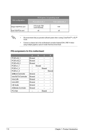
... recommend that you provide sufficient power when running CrossFireX™ or SLI™ mode. • Connect a chassis fan to the motherboard connector labeled CHA_FAN1-4 when using multiple graphics cards for this motherboard PCIE x16_1 PCIE x16_2 PCIE x16_3 PCIE x1_1 PCIE x1_2 PCIE x1_3 SMBUS Controller Intel SATA Controller Intel LAN Intel...
... recommend that you provide sufficient power when running CrossFireX™ or SLI™ mode. • Connect a chassis fan to the motherboard connector labeled CHA_FAN1-4 when using multiple graphics cards for this motherboard PCIE x16_1 PCIE x16_2 PCIE x16_3 PCIE x1_1 PCIE x1_2 PCIE x1_3 SMBUS Controller Intel SATA Controller Intel LAN Intel...
User Guide
Page 37
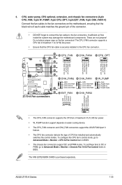
These are not jumpers! Insufficient air flow inside the system may damage the motherboard components. The CPU_FAN connector supports a CPU fan of maximum 1 A (12 W) fan power. • Ensure that the CPU fan cable is purchased separately. ASUS Z170-A Series 1-25 To set these fans to DC or PWM, go to ...• The CPU_FAN connector supports the CPU fan of maximum 1A (12 W) fan power. • W_PUMP function support depends on the motherboard, ensuring that the black wire of each cable matches the ground pin of CPU fan installed and automatically switches the control modes. The FAN ...
These are not jumpers! Insufficient air flow inside the system may damage the motherboard components. The CPU_FAN connector supports a CPU fan of maximum 1 A (12 W) fan power. • Ensure that the CPU fan cable is purchased separately. ASUS Z170-A Series 1-25 To set these fans to DC or PWM, go to ...• The CPU_FAN connector supports the CPU fan of maximum 1A (12 W) fan power. • W_PUMP function support depends on the motherboard, ensuring that the black wire of each cable matches the ground pin of CPU fan installed and automatically switches the control modes. The FAN ...
User Guide
Page 39
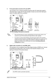
...system chassis. Connect the S/PDIF Out module cable to this connector, then install the module to a slot opening at the back of the motherboard's high-definition audio capability. • If you want to connect an AC'97 front panel audio module to this connector is for an ... is set the Front Panel Type item in the BIOS setup to [HD Audio]. Digital audio connector (4-1 pin SPDIF_OUT) This connector is purchased separately. ASUS Z170-A Series 1-27 If you connect a high-definition front panel audio module to this connector, set to [HD Audio]. The S/PDIF module is for ...
...system chassis. Connect the S/PDIF Out module cable to this connector, then install the module to a slot opening at the back of the motherboard's high-definition audio capability. • If you want to connect an AC'97 front panel audio module to this connector is for an ... is set the Front Panel Type item in the BIOS setup to [HD Audio]. Digital audio connector (4-1 pin SPDIF_OUT) This connector is purchased separately. ASUS Z170-A Series 1-27 If you connect a high-definition front panel audio module to this connector, set to [HD Audio]. The S/PDIF module is for ...
User Guide
Page 40
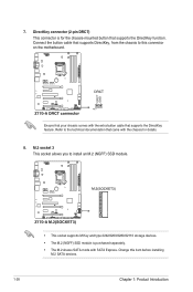
... DirectKey, from the chassis to the technical documentation that came with the extra button cable that supports the DirectKey function. Change this connector on the motherboard. Refer to this item before installing M.2 SATA devices. 1-28 Chapter 1: Product Introduction Ensure that your chassis comes with the chassis for the chassis-mounted button...
... DirectKey, from the chassis to the technical documentation that came with the extra button cable that supports the DirectKey function. Change this connector on the motherboard. Refer to this item before installing M.2 SATA devices. 1-28 Chapter 1: Product Introduction Ensure that your chassis comes with the chassis for the chassis-mounted button...

User Guide
Page 41
... connectors. Never connect a 1394 cable to fully use the USB 2.0 ports under Windows® 7. 10. ASUS Z170-A Series 1-29 USB 2.0 connectors (10-1 pin USB1112, USB1314) These connectors are based on xHCI specification. 9. Doing so will damage the motherboard! TPM connector (14-1 pin TPM) This connector supports a Trusted Platform Module (TPM) system, which securely...
... connectors. Never connect a 1394 cable to fully use the USB 2.0 ports under Windows® 7. 10. ASUS Z170-A Series 1-29 USB 2.0 connectors (10-1 pin USB1112, USB1314) These connectors are based on xHCI specification. 9. Doing so will damage the motherboard! TPM connector (14-1 pin TPM) This connector supports a Trusted Platform Module (TPM) system, which securely...
User Guide
Page 44
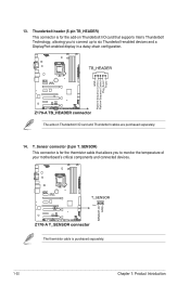
.... T_Sensor connector (2-pin T_SENSOR) This connector is for the add-on Thunderbolt I /O card that allows you to connect up to monitor the temperature of your motherboard's critical components and connected devices. The thermistor cable is for the thermistor cable that supports Intel's Thunderbolt Technology, allowing you to six Thunderbolt-enabled devices...
.... T_Sensor connector (2-pin T_SENSOR) This connector is for the add-on Thunderbolt I /O card that allows you to connect up to monitor the temperature of your motherboard's critical components and connected devices. The thermistor cable is for the thermistor cable that supports Intel's Thunderbolt Technology, allowing you to six Thunderbolt-enabled devices...
User Guide
Page 46
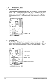
... critical component's LED stays lit up to indicate that you should shut down the system and unplug the power cable before removing or plugging any motherboard components. 1.8 Onboard LEDs 1. POST State LEDs The POST State LEDs provide the status of the onboard LED. 2. This is solved. 1-34 Chapter ...1: Product Introduction Standby Power LED The motherboard comes with a standby power LED that lights up until the problem is a reminder that the system is ON, in sleep mode, or in soft...
... critical component's LED stays lit up to indicate that you should shut down the system and unplug the power cable before removing or plugging any motherboard components. 1.8 Onboard LEDs 1. POST State LEDs The POST State LEDs provide the status of the onboard LED. 2. This is solved. 1-34 Chapter ...1: Product Introduction Standby Power LED The motherboard comes with a standby power LED that lights up until the problem is a reminder that the system is ON, in sleep mode, or in soft...
User Guide
Page 48
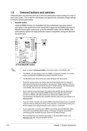
... continuously. MemOK! Turn off the computer and replace DIMMs during POST stage and the DRAM_LED near the MemOK! Replace the DIMMs with the motherboard may cause system boot failure. If the test fails, the system reboots and test the next set of the DRAM_LED increases, indicating different ... failsafe memory settings. 1.9 Onboard buttons and switches Onboard buttons and switches allow you download and update to the latest BIOS version from www.asus.com after using the MemOK! This is tested. To stop memory tuning, turn off the system and reinstall the DIMM before using the MemOK...
... continuously. MemOK! Turn off the computer and replace DIMMs during POST stage and the DRAM_LED near the MemOK! Replace the DIMMs with the motherboard may cause system boot failure. If the test fails, the system reboots and test the next set of the DRAM_LED increases, indicating different ... failsafe memory settings. 1.9 Onboard buttons and switches Onboard buttons and switches allow you download and update to the latest BIOS version from www.asus.com after using the MemOK! This is tested. To stop memory tuning, turn off the system and reinstall the DIMM before using the MemOK...


