
Users Manual English
Page 1
Motherboard TUF Z390M-PRO GAMING
Motherboard TUF Z390M-PRO GAMING

Users Manual English
Page 3
Contents Safety information...vi About this guide...vii TUF Z390M-PRO GAMING specifications summary ix Package contents...xiii Installation tools and components xiv Chapter 1: Product Introduction 1.1 Motherboard overview 1-1 1.1.1 Before you proceed 1-1 1.1.2 Motherboard layout 1-2 1.1.3 Central Processing Unit (CPU 1-4 1.1.4 System memory 1-5 1.1.5 Expansion slots 1-7 1.1.6 Onboard switches 1-9 1.1.7 Jumpers 1-10 1.1.8 Onboard LEDs 1-11 1.1.9 Internal connectors 1-12 Chapter 2: Basic Installation 2.1 Building your PC...
Contents Safety information...vi About this guide...vii TUF Z390M-PRO GAMING specifications summary ix Package contents...xiii Installation tools and components xiv Chapter 1: Product Introduction 1.1 Motherboard overview 1-1 1.1.1 Before you proceed 1-1 1.1.2 Motherboard layout 1-2 1.1.3 Central Processing Unit (CPU 1-4 1.1.4 System memory 1-5 1.1.5 Expansion slots 1-7 1.1.6 Onboard switches 1-9 1.1.7 Jumpers 1-10 1.1.8 Onboard LEDs 1-11 1.1.9 Internal connectors 1-12 Chapter 2: Basic Installation 2.1 Building your PC...

Users Manual English
Page 6
... the manuals that all cables are correctly connected and the power cables are using an adapter or extension cord. Operation safety • Before installing the motherboard and adding devices on it may become wet. • Place the product on a stable surface. • If you are not damaged. If you add ... and staples away from connectors, slots, sockets and circuitry. • Avoid dust, humidity, and temperature extremes. If possible, disconnect all power cables from the motherboard, ensure that came with the product, contact a qualified service technician or your retailer.
... the manuals that all cables are correctly connected and the power cables are using an adapter or extension cord. Operation safety • Before installing the motherboard and adding devices on it may become wet. • Place the product on a stable surface. • If you are not damaged. If you add ... and staples away from connectors, slots, sockets and circuitry. • Avoid dust, humidity, and temperature extremes. If possible, disconnect all power cables from the motherboard, ensure that came with the product, contact a qualified service technician or your retailer.

Users Manual English
Page 7
... 1: Product Introduction This chapter describes the features of the standard package. Chapter 4: RAID Support This chapter describes the RAID configurations. ASUS website The ASUS website (www.asus.com) provides updated information on the motherboard. 2. Optional documentation Your product package may have to perform when installing system components. 3. Detailed descriptions of the switches, jumpers, and...
... 1: Product Introduction This chapter describes the features of the standard package. Chapter 4: RAID Support This chapter describes the RAID configurations. ASUS website The ASUS website (www.asus.com) provides updated information on the motherboard. 2. Optional documentation Your product package may have to perform when installing system components. 3. Detailed descriptions of the switches, jumpers, and...

Users Manual English
Page 13
Package contents Check your motherboard package for the following items. Motherboard Cables Accessories Application drive Documentation TUF Z390M-PRO GAMING 2 x SATA 6Gb/s cables 1 x IO Shield 1 x M.2 screw package (2-in-1) 1 x Q-connector 1 x SLITM HB BRIDGE (2-WAY-S) 1 x TUF GAMING sticker 1 x support DVD 1 x User guide 1 x TUF Certification card If any of the above items is damaged or missing, contact your retailer. xiii
Package contents Check your motherboard package for the following items. Motherboard Cables Accessories Application drive Documentation TUF Z390M-PRO GAMING 2 x SATA 6Gb/s cables 1 x IO Shield 1 x M.2 screw package (2-in-1) 1 x Q-connector 1 x SLITM HB BRIDGE (2-WAY-S) 1 x TUF GAMING sticker 1 x support DVD 1 x User guide 1 x TUF Certification card If any of the above items is damaged or missing, contact your retailer. xiii

Users Manual English
Page 14
Installation tools and components Intel® 1151 compatible CPU Fan Intel® 1151 CPU PC chassis SATA hard disk drive Phillips (cross) screwdriver Power supply unit 1 bag of screws DIMM SATA optical disc drive (optional) Graphics card The tools and components listed above are not included in the motherboard package. xiv
Installation tools and components Intel® 1151 compatible CPU Fan Intel® 1151 CPU PC chassis SATA hard disk drive Phillips (cross) screwdriver Power supply unit 1 bag of screws DIMM SATA optical disc drive (optional) Graphics card The tools and components listed above are not included in the motherboard package. xiv

Users Manual English
Page 15
... pad or in the bag that came with the component. • Before you install motherboard components or change any motherboard settings. • Unplug the power cord from the power supply. ASUS TUF Z390M-PRO GAMING 1-1 Chapter 1 Chapter 1: Product Introduction Product Introduction 1 1.1 Motherboard overview 1.1.1 Before you proceed Take note of the following precautions before you install or remove... a metal object, such as the power supply case, to avoid damaging them due to static electricity. • Hold components by the edges to the motherboard, peripherals, or components.
... pad or in the bag that came with the component. • Before you install motherboard components or change any motherboard settings. • Unplug the power cord from the power supply. ASUS TUF Z390M-PRO GAMING 1-1 Chapter 1 Chapter 1: Product Introduction Product Introduction 1 1.1 Motherboard overview 1.1.1 Before you proceed Take note of the following precautions before you install or remove... a metal object, such as the power supply case, to avoid damaging them due to static electricity. • Hold components by the edges to the motherboard, peripherals, or components.

Users Manual English
Page 16
Chapter 1 1.1.2 Motherboard layout 1 2 3 24 24.4cm(9.6in) 5 KBMS EATX12V CPU_FAN 6 DIGI+ VRM CPU_OPT DP ® DDR4 DIMM_B1 (64bit, 288-pin module) DDR4 DIMM_B2* (64bit, 288-pin module) ...
Chapter 1 1.1.2 Motherboard layout 1 2 3 24 24.4cm(9.6in) 5 KBMS EATX12V CPU_FAN 6 DIGI+ VRM CPU_OPT DP ® DDR4 DIMM_B1 (64bit, 288-pin module) DDR4 DIMM_B2* (64bit, 288-pin module) ...

Users Manual English
Page 18
...8226; Keep the cap after installing the motherboard. ® Chapter 1 1.1.3 Central Processing Unit (CPU) The motherboard comes with the cap on the socket and the socket contacts are not bent. TUF Z390M-PRO GAMING CPU LGA1151 • Ensure that the ...PnP cap is missing, or if you install the correct CPU designed for Intel® Core™ 9000 series, 8th Generation Core™ i7/ i5/ i3, Pentium® and Celeron® processors. ASUS will process Return Merchandise Authorization (RMA) requests only if the motherboard...
...8226; Keep the cap after installing the motherboard. ® Chapter 1 1.1.3 Central Processing Unit (CPU) The motherboard comes with the cap on the socket and the socket contacts are not bent. TUF Z390M-PRO GAMING CPU LGA1151 • Ensure that the ...PnP cap is missing, or if you install the correct CPU designed for Intel® Core™ 9000 series, 8th Generation Core™ i7/ i5/ i3, Pentium® and Celeron® processors. ASUS will process Return Merchandise Authorization (RMA) requests only if the motherboard...

Users Manual English
Page 19
TUF Z390M-PRO GAMING 288-pin DDR4 DIMM sockets Recommended memory configurations DIMM_A2* DIMM_B2* DIMM_A2* DIMM_B1 DIMM_B2* DIMM_A1 DIMM_A2* ASUS TUF Z390M-PRO GAMING 1-5 DO NOT install a DDR, DDR2, or DDR3 memory module to the DDR4 slot. A DDR4 module is notched differently from a DDR, DDR2, or DDR3 module. ® DIMM_B1 DIMM_B2* DIMM_A1 DIMM_A2* Chapter 1 1.1.4 System memory The motherboard comes with four DDR4 (Double Data Rate 4) Dual Inline Memory Modules (DIMM) slots.
TUF Z390M-PRO GAMING 288-pin DDR4 DIMM sockets Recommended memory configurations DIMM_A2* DIMM_B2* DIMM_A2* DIMM_B1 DIMM_B2* DIMM_A1 DIMM_A2* ASUS TUF Z390M-PRO GAMING 1-5 DO NOT install a DDR, DDR2, or DDR3 memory module to the DDR4 slot. A DDR4 module is notched differently from a DDR, DDR2, or DDR3 module. ® DIMM_B1 DIMM_B2* DIMM_A1 DIMM_A2* Chapter 1 1.1.4 System memory The motherboard comes with four DDR4 (Double Data Rate 4) Dual Inline Memory Modules (DIMM) slots.

Users Manual English
Page 21
1.1.5 Expansion slots Unplug the power cord before adding or removing expansion cards. Failure to do so may cause you physical injury and damage motherboard components. ® Chapter 1 PCIEX16_1 PCIEX16_2 PCIEX1 Slot No. 1 2 3 Slot Description PCIEx16_1 slot PCIEx16_2 slot PCIEx1 slot ASUS TUF Z390M-PRO GAMING 1-7
1.1.5 Expansion slots Unplug the power cord before adding or removing expansion cards. Failure to do so may cause you physical injury and damage motherboard components. ® Chapter 1 PCIEX16_1 PCIEX16_2 PCIEX1 Slot No. 1 2 3 Slot Description PCIEx16_1 slot PCIEx16_2 slot PCIEx1 slot ASUS TUF Z390M-PRO GAMING 1-7

Users Manual English
Page 22
... get better performance. • We recommend that you provide sufficient power when running CrossFireX™ or SLI™ mode. • Connect a chassis fan to the motherboard connector labeled CHA_FAN1-2 when using multiple graphics cards for better thermal environment.
... get better performance. • We recommend that you provide sufficient power when running CrossFireX™ or SLI™ mode. • Connect a chassis fan to the motherboard connector labeled CHA_FAN1-2 when using multiple graphics cards for better thermal environment.

Users Manual English
Page 23
... switch is enabled by default, allowing memory re-training when the motherboard is unresponsive due to test one set of profiles. To stop memory...TUF Z390M-PRO GAMING MemOK! If the test fails, the system reboots and tests the next set the MemOK! switch • Refer to replace the DIMMs with ones recommended in the Memory QVL (Qualified Vendors Lists) at www.asus.com. • We recommend that are not compatible with the motherboard... is tested. • If you turn off, please refrain from www.asus.com after turning on the computer. II function. ASUS TUF Z390M-PRO GAMING 1-9
... switch is enabled by default, allowing memory re-training when the motherboard is unresponsive due to test one set of profiles. To stop memory...TUF Z390M-PRO GAMING MemOK! If the test fails, the system reboots and tests the next set the MemOK! switch • Refer to replace the DIMMs with ones recommended in the Memory QVL (Qualified Vendors Lists) at www.asus.com. • We recommend that are not compatible with the motherboard... is tested. • If you turn off, please refrain from www.asus.com after turning on the computer. II function. ASUS TUF Z390M-PRO GAMING 1-9
Users Manual English
Page 27
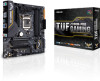
... SENSE2_RETUR ® ® PORT1 L PORT1 R PORT2 R SENSE_SEND PORT2 L AAFP HD-audio-compliant pin definition TUF Z390M-PRO GAMING Analog front panel connector We recommend that supports HD Audio. ASUS TUF Z390M-PRO GAMING 1-13 The latest USB 3.1 Gen 2 connectivity provides data transfer speeds of the motherboard's high-definition audio capability. 3. U31G2_C3 SBU2 SBU1 CC1 VBUS RX1RX1+ GND TX1TX1+ VBUS VBUS...
... SENSE2_RETUR ® ® PORT1 L PORT1 R PORT2 R SENSE_SEND PORT2 L AAFP HD-audio-compliant pin definition TUF Z390M-PRO GAMING Analog front panel connector We recommend that supports HD Audio. ASUS TUF Z390M-PRO GAMING 1-13 The latest USB 3.1 Gen 2 connectivity provides data transfer speeds of the motherboard's high-definition audio capability. 3. U31G2_C3 SBU2 SBU1 CC1 VBUS RX1RX1+ GND TX1TX1+ VBUS VBUS...

Users Manual English
Page 28
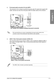
...GND IntA_P1_DIntA_P1_D+ GND ® Vbus IntA_P2_SSRXIntA_P2_SSRX+ GND IntA_P2_SSTXIntA_P2_SSTX+ GND IntA_P2_DIntA_P2_D+ TUF Z390M-PRO GAMING USB 3.1 Gen 1 connector The USB 3.1 Gen1 module is purchased separately. 1-14 Chapter 1: Product Introduction 4. Doing so will damage the motherboard! With an installed USB 3.1 Gen1 module, you to 5 Gb/s,...+ GND NC USB+5V USB_P4USB_P4+ GND NC USB+5V USB_P11USB_P11+ GND USB+5V USB_P3USB_P3+ GND PIN 1 PIN 1 TUF Z390M-PRO GAMING USB2.0 connectors DO NOT connect a 1394 cable to a slot opening at the back of the system chassis. These ...
...GND IntA_P1_DIntA_P1_D+ GND ® Vbus IntA_P2_SSRXIntA_P2_SSRX+ GND IntA_P2_SSTXIntA_P2_SSTX+ GND IntA_P2_DIntA_P2_D+ TUF Z390M-PRO GAMING USB 3.1 Gen 1 connector The USB 3.1 Gen1 module is purchased separately. 1-14 Chapter 1: Product Introduction 4. Doing so will damage the motherboard! With an installed USB 3.1 Gen1 module, you to 5 Gb/s,...+ GND NC USB+5V USB_P4USB_P4+ GND NC USB+5V USB_P11USB_P11+ GND USB+5V USB_P3USB_P3+ GND PIN 1 PIN 1 TUF Z390M-PRO GAMING USB2.0 connectors DO NOT connect a 1394 cable to a slot opening at the back of the system chassis. These ...
Users Manual English
Page 29
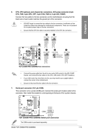
...• DO NOT forget to connect the fan cables to the fan connector. 7. ASUS TUF Z390M-PRO GAMING 1-15 Insufficient air flow inside the system may need to use a pigtail cable to connect the cooler to the motherboard. • Ensure to fully insert the fan cable to the fan connectors. These ...system chassis. ® RXD1 DTR1 DSR1 CTS1 COM PIN 1 DCD1 TXD1 GND RTS1# PI1# TUF Z390M-PRO GAMING Serial port connector The COM module is securely installed to the CPU_FAN and/or CPU_OPT header(s). • If your AIO cooler has more than one fan, you may damage the motherboard components.
...• DO NOT forget to connect the fan cables to the fan connector. 7. ASUS TUF Z390M-PRO GAMING 1-15 Insufficient air flow inside the system may need to use a pigtail cable to connect the cooler to the motherboard. • Ensure to fully insert the fan cable to the fan connectors. These ...system chassis. ® RXD1 DTR1 DSR1 CTS1 COM PIN 1 DCD1 TXD1 GND RTS1# PI1# TUF Z390M-PRO GAMING Serial port connector The COM module is securely installed to the CPU_FAN and/or CPU_OPT header(s). • If your AIO cooler has more than one fan, you may damage the motherboard components.
Users Manual English
Page 33
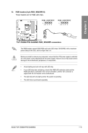
... the correct orientation, and the 12V connector is aligned with a maximum power rating of 3A (12V), and no longer than 3 m. ASUS TUF Z390M-PRO GAMING 1-19 ® Chapter 1 12. RGB headers (4-pin RGB_HEADER1/2) These headers are for RGB LED strips. Before you install or remove any... separately. RGB_HEADER1 PIN 1 +12V G R B RGB_HEADER2 PIN 1 +12V G R B TUF Z390M-PRO GAMING RGB_HEADER connectors The RGB headers support 5050 RGB multi-color LED strips (12V/G/R/B), with the 12V header on the motherboard. • The LED strip will only light up when the system is operating. •...
... the correct orientation, and the 12V connector is aligned with a maximum power rating of 3A (12V), and no longer than 3 m. ASUS TUF Z390M-PRO GAMING 1-19 ® Chapter 1 12. RGB headers (4-pin RGB_HEADER1/2) These headers are for RGB LED strips. Before you install or remove any... separately. RGB_HEADER1 PIN 1 +12V G R B RGB_HEADER2 PIN 1 +12V G R B TUF Z390M-PRO GAMING RGB_HEADER connectors The RGB headers support 5050 RGB multi-color LED strips (12V/G/R/B), with the 12V header on the motherboard. • The LED strip will only light up when the system is operating. •...
Users Manual English
Page 35
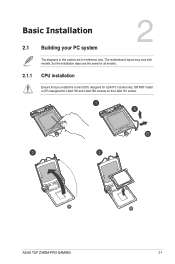
Chapter 2: Basic Installation Basic Installation 2.1 Building your PC system 2 The diagrams in this section are the same for all models. 2.1.1 CPU installation Ensure that you install the correct CPU designed for LGA1151 socket only. Chapter 2 ASUS TUF Z390M-PRO GAMING 2-1 DO NOT install a CPU designed for reference only. The motherboard layout may vary with models, but the installation steps are for LGA1155 and LGA1156 sockets on the LGA1151 socket.
Chapter 2: Basic Installation Basic Installation 2.1 Building your PC system 2 The diagrams in this section are the same for all models. 2.1.1 CPU installation Ensure that you install the correct CPU designed for LGA1151 socket only. Chapter 2 ASUS TUF Z390M-PRO GAMING 2-1 DO NOT install a CPU designed for reference only. The motherboard layout may vary with models, but the installation steps are for LGA1155 and LGA1156 sockets on the LGA1151 socket.

Users Manual English
Page 38
To install an AIO cooler Chapter 2 AIO_PUMP CPU_FAN CPU_OPT The illustrations in this section are for the actual location of the header(s). 2-4 Chapter 2: Basic Installation Please refer to section 1.1.2 Motherboard Layout for reference only.
To install an AIO cooler Chapter 2 AIO_PUMP CPU_FAN CPU_OPT The illustrations in this section are for the actual location of the header(s). 2-4 Chapter 2: Basic Installation Please refer to section 1.1.2 Motherboard Layout for reference only.
Users Manual English
Page 39
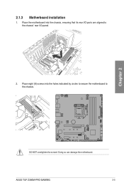
ASUS TUF Z390M-PRO GAMING 2-5 Place the motherboard into the holes indicated by circles to secure the motherboard to the chassis' rear I /O ports are aligned to the chassis. ® Chapter 2 DO NOT overtighten the screws! Doing so can damage the motherboard. Place eight (8) screws into the chassis, ensuring that its rear I /O panel. 2. 2.1.3 Motherboard installation 1.
ASUS TUF Z390M-PRO GAMING 2-5 Place the motherboard into the holes indicated by circles to secure the motherboard to the chassis' rear I /O ports are aligned to the chassis. ® Chapter 2 DO NOT overtighten the screws! Doing so can damage the motherboard. Place eight (8) screws into the chassis, ensuring that its rear I /O panel. 2. 2.1.3 Motherboard installation 1.


