
User Guide
Page 13
ASUS TS100-E7/PI4 Product introduction Chapter 1 This chapter describes the general features of the server, including sections on front panel and rear panel specifications.
ASUS TS100-E7/PI4 Product introduction Chapter 1 This chapter describes the general features of the server, including sections on front panel and rear panel specifications.
User Guide
Page 15
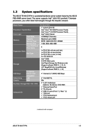
...Type Storage HDD Bays Networking Graphic I = internal A or S = hotswappable LAN VGA Auxiliary Storage FDD / CD / DVD Onboard I/O TS100-E7/PI4 1* socket LGA1155 Intel® Xeon® E3-1200 Processor Family Intel® Core™ i3-2100 Processor Family Intel® C202 Chipset...4* USB 2.0 ports (Front * 2, Rear * 2) 1 * VGA port 1 * PS/2 keyboard port 1 * PS/2 mouse port (continued on the next page) ASUS TS100-E7/PI4 1-3 The server supports Intel® LGA1155 Lynnfield / Clarkdale processors, plus other latest technologies through the chipsets onboard. 1.3 System specifications The...
...Type Storage HDD Bays Networking Graphic I = internal A or S = hotswappable LAN VGA Auxiliary Storage FDD / CD / DVD Onboard I/O TS100-E7/PI4 1* socket LGA1155 Intel® Xeon® E3-1200 Processor Family Intel® Core™ i3-2100 Processor Family Intel® C202 Chipset...4* USB 2.0 ports (Front * 2, Rear * 2) 1 * VGA port 1 * PS/2 keyboard port 1 * PS/2 mouse port (continued on the next page) ASUS TS100-E7/PI4 1-3 The server supports Intel® LGA1155 Lynnfield / Clarkdale processors, plus other latest technologies through the chipsets onboard. 1.3 System specifications The...

User Guide
Page 17
... the LED descriptions. The drive bays, power and reset buttons, LED indicators, CD/DVD-ROM drive, and USB 2.0 ports are located on the front panel. ASUS TS100-E7/PI4 1-5 The power and reset buttons, LED indicators, optical drive, and two USB ports are located on the front panel. 1.4 Front panel features The barebone server...
... the LED descriptions. The drive bays, power and reset buttons, LED indicators, CD/DVD-ROM drive, and USB 2.0 ports are located on the front panel. ASUS TS100-E7/PI4 1-5 The power and reset buttons, LED indicators, optical drive, and two USB ports are located on the front panel. 1.4 Front panel features The barebone server...

User Guide
Page 19
... a USB floppy disk drive or a USB ODD to use a floppy disk or a optical disc. *WARNING HAZARDOUS MOVING PARTS KEEP FINGERS AND OTHER BODY PARTS AWAY ASUS TS100-E7/PI4 1-7 The barebone server does not include a floppy disk drive and an optical disc drive. Optical drive 6. 2 x 5.25-inch drive bays...
... a USB floppy disk drive or a USB ODD to use a floppy disk or a optical disc. *WARNING HAZARDOUS MOVING PARTS KEEP FINGERS AND OTHER BODY PARTS AWAY ASUS TS100-E7/PI4 1-7 The barebone server does not include a floppy disk drive and an optical disc drive. Optical drive 6. 2 x 5.25-inch drive bays...

User Guide
Page 21
ASUS TS100-E7/PI4 Hardware setup Chapter 2 This chapter lists the hardware setup procedures that you have to perform when installing or removing system components.
ASUS TS100-E7/PI4 Hardware setup Chapter 2 This chapter lists the hardware setup procedures that you have to perform when installing or removing system components.

User Guide
Page 23
Position the side cover to secure the side cover. 4 ASUS TS100-E7/PI4 4 2-3 Drive in place. 3 4. Slide the side cover toward the front panel until it snaps in the two screws you removed earlier to the chassis. 1 3. Match and insert the lower sliding edge of the side cover to the corresponding chassis edge. 2. 2.1.2 Reinstalling the side cover To reinstall the side cover: 1.
Position the side cover to secure the side cover. 4 ASUS TS100-E7/PI4 4 2-3 Drive in place. 3 4. Slide the side cover toward the front panel until it snaps in the two screws you removed earlier to the chassis. 1 3. Match and insert the lower sliding edge of the side cover to the corresponding chassis edge. 2. 2.1.2 Reinstalling the side cover To reinstall the side cover: 1.

User Guide
Page 25
... on the socket and damaging the CPU! DO NOT force the CPU into the CPU notches. 3. PnP cap Cap tab 5. Gold triangle mark Alignment keys ASUS TS100-E7/PI4 CPU notches 2-5 Lift the load lever in only one correct orientation. Position the CPU over the socket, ensuring that the gold triangle is completely lifted.
... on the socket and damaging the CPU! DO NOT force the CPU into the CPU notches. 3. PnP cap Cap tab 5. Gold triangle mark Alignment keys ASUS TS100-E7/PI4 CPU notches 2-5 Lift the load lever in only one correct orientation. Position the CPU over the socket, ensuring that the gold triangle is completely lifted.

User Guide
Page 27
B 2. ASUS TS100-E7/PI4 2-7 2.2.2 Installing the CPU heatsink and fan The Intel® LGA1155 processor requires a specially designed heatsink and fan assembly to ensure optimum thermal condition and performance. &#...
B 2. ASUS TS100-E7/PI4 2-7 2.2.2 Installing the CPU heatsink and fan The Intel® LGA1155 processor requires a specially designed heatsink and fan assembly to ensure optimum thermal condition and performance. &#...

User Guide
Page 29
2.3 System memory 2.3.1 Overview The motherboard comes with the same CAS latency. ASUS TS100-E7/PI4 2-9 UDIMM DIMM Slot DIMM Populated DIMM Type Per Channel per Channel Speed Rank per DIMM 2 1 Unbuffered DDR3 ECC 1066/1333 Single Rank, Dual Rank 2 2 Unbuffered ...
2.3 System memory 2.3.1 Overview The motherboard comes with the same CAS latency. ASUS TS100-E7/PI4 2-9 UDIMM DIMM Slot DIMM Populated DIMM Type Per Channel per Channel Speed Rank per DIMM 2 1 Unbuffered DDR3 ECC 1066/1333 Single Rank, Dual Rank 2 2 Unbuffered ...

User Guide
Page 31
ASUS TS100-E7/PI4 2-11 Hook the other side of the front panel cover to the chassis. 2. Swing the front panel cover and snap it back into place. Release the hooked tabs and take off the front panel cover. 2.4.2 Reinstalling the front panel cover To reinstall the front panel cover: 1. 2.4 Front panel cover Before you can install a 5.25-inch drive, you should first remove the front panel cover. 2.4.1 Removing the front panel cover To remove the front panel cover: 1. Locate the three hooked tabs on the chassis side rail. 2.
ASUS TS100-E7/PI4 2-11 Hook the other side of the front panel cover to the chassis. 2. Swing the front panel cover and snap it back into place. Release the hooked tabs and take off the front panel cover. 2.4.2 Reinstalling the front panel cover To reinstall the front panel cover: 1. 2.4 Front panel cover Before you can install a 5.25-inch drive, you should first remove the front panel cover. 2.4.1 Removing the front panel cover To remove the front panel cover: 1. Locate the three hooked tabs on the chassis side rail. 2.

User Guide
Page 33
Follow the instructions on the previous section to the right until it clicks in place. 6. Connect a power plug from the power supply to the SATA connector on the back of the drive. 7. Slide the bay lock to reinstall the front panel cover. ASUS TS100-E7/PI4 2-13 4. Connect the SATA cable to the power connector on the back of the drive. 76 8. Insert the drive into the bay. 5.
Follow the instructions on the previous section to the right until it clicks in place. 6. Connect a power plug from the power supply to the SATA connector on the back of the drive. 7. Slide the bay lock to reinstall the front panel cover. ASUS TS100-E7/PI4 2-13 4. Connect the SATA cable to the power connector on the back of the drive. 76 8. Insert the drive into the bay. 5.

User Guide
Page 35
Failure to do so may cause severe damage to unlock it and make the necessary hardware settings for you wish to install an expansion card. ASUS TS100-E7/PI4 2-15 Lay the system on its side on the rear panel for the card. 2. Push down the �e�x�p�a�n��s�...
Failure to do so may cause severe damage to unlock it and make the necessary hardware settings for you wish to install an expansion card. ASUS TS100-E7/PI4 2-15 Lay the system on its side on the rear panel for the card. 2. Push down the �e�x�p�a�n��s�...
User Guide
Page 37
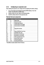
... 15* 10 Secondary IDE Channel * These IRQs are usually available for the expansion card. Assign an IRQ to the following tables. 3. Turn on BIOS setup. 2. ASUS TS100-E7/PI4 2-17 See Chapter 5 for information on the system and change the necessary BIOS settings, if any. Refer to the card.
... 15* 10 Secondary IDE Channel * These IRQs are usually available for the expansion card. Assign an IRQ to the following tables. 3. Turn on BIOS setup. 2. ASUS TS100-E7/PI4 2-17 See Chapter 5 for information on the system and change the necessary BIOS settings, if any. Refer to the card.

User Guide
Page 39
... conectors (system default; from power supply to front I /O board) 6. System fan connector (from motherboard to motherboard) 3. System panel connector (from system fan to front I /O board) ASUS TS100-E7/PI4 2-19 USB connector (from motherboard to motherboard) 4. 2.9 Cable connections • The bundled system cables are pre-connected before shipment.
... conectors (system default; from power supply to front I /O board) 6. System fan connector (from motherboard to motherboard) 3. System panel connector (from system fan to front I /O board) ASUS TS100-E7/PI4 2-19 USB connector (from motherboard to motherboard) 4. 2.9 Cable connections • The bundled system cables are pre-connected before shipment.

User Guide
Page 41
Motherboard Info Chapter 3 This chapter includes the motherboard layout and brief descriptions of the jumpers and internal connectors. ASUS TS100-E7/PI4
Motherboard Info Chapter 3 This chapter includes the motherboard layout and brief descriptions of the jumpers and internal connectors. ASUS TS100-E7/PI4

User Guide
Page 43
... 1. ATX power connectors (24-pin EATXPWR1, 8-pin EATX12V1) 10. Auxiliary panel connector (20-2 pin AUX_PANEL1) Page 3-8 3-9 3-10 3-10 3-11 3-12 3-12 3-13 3-14 3-15 3-16 ASUS TS100-E7/PI4 3-3 A-Type USB7) 4. Intel® C202 SATA port S/W RAID setting (3-pin RAID_SEL1) 6. CPU, front and rear fan connectors (4-pin CPU_FAN1, FRNT_FAN1, FRNT_FAN2, FRNT_FAN3, REAR_FAN1) 6. Layout contents...
... 1. ATX power connectors (24-pin EATXPWR1, 8-pin EATX12V1) 10. Auxiliary panel connector (20-2 pin AUX_PANEL1) Page 3-8 3-9 3-10 3-10 3-11 3-12 3-12 3-13 3-14 3-15 3-16 ASUS TS100-E7/PI4 3-3 A-Type USB7) 4. Intel® C202 SATA port S/W RAID setting (3-pin RAID_SEL1) 6. CPU, front and rear fan connectors (4-pin CPU_FAN1, FRNT_FAN1, FRNT_FAN2, FRNT_FAN3, REAR_FAN1) 6. Layout contents...

User Guide
Page 45
... VGA feature. 3. Set to pins 1-2 when using 4-pin fans or pins 2-3 when using 3-pin fans. • If you installed will always run at full speed. ASUS TS100-E7/PI4 3-5 VGA controller setting (3-pin VGA_SW1) This jumper allows you to enable or disable the onboard VGA controller. CPU Fan and Chassis Fan control setting (3-pin...
... VGA feature. 3. Set to pins 1-2 when using 4-pin fans or pins 2-3 when using 3-pin fans. • If you installed will always run at full speed. ASUS TS100-E7/PI4 3-5 VGA controller setting (3-pin VGA_SW1) This jumper allows you to enable or disable the onboard VGA controller. CPU Fan and Chassis Fan control setting (3-pin...

User Guide
Page 47
Prepare a USB flash disk that contains the original or latest BIOS for the motherboard (XXXXXX.ROM) and the BUPDATER.EXE utility. 2. Set the jumper back to update the BIOS. 4. Insert the USB flash and turn on the system. Turn on the system to pins 1-2. 6. ASUS TS100-E7/PI4 3-7 Force BIOS recovery setting (3-pin RECOVERY1) This jumper allows you to pins 2-3. 3. 6. Set the jumper to quickly update or recover the BIOS settings when it becomes corrupted. To update the BIOS: 1. Shut down the system. 5.
Prepare a USB flash disk that contains the original or latest BIOS for the motherboard (XXXXXX.ROM) and the BUPDATER.EXE utility. 2. Set the jumper back to update the BIOS. 4. Insert the USB flash and turn on the system. Turn on the system to pins 1-2. 6. ASUS TS100-E7/PI4 3-7 Force BIOS recovery setting (3-pin RECOVERY1) This jumper allows you to pins 2-3. 3. 6. Set the jumper to quickly update or recover the BIOS settings when it becomes corrupted. To update the BIOS: 1. Shut down the system. 5.

User Guide
Page 49
ASUS TS100-E7/PI4 3-9 The read or write activities of any device connected to light up. 2. Hard disk activity LED connector (4-pin HDLED1) This LED connector is for the storage add-on card cable connected to the SATA or SAS add-on card causes the front panel LED to the SATA or SAS add-on card.
ASUS TS100-E7/PI4 3-9 The read or write activities of any device connected to light up. 2. Hard disk activity LED connector (4-pin HDLED1) This LED connector is for the storage add-on card cable connected to the SATA or SAS add-on card causes the front panel LED to the SATA or SAS add-on card.

User Guide
Page 51
... jumper caps on the motherboard, ensuring that the black wire of each cable matches the ground pin of 3.15 A-6.66 A (53.28 W max.) at +12V. ASUS TS100-E7/PI4 3-11 Connect the fan cables to the fan connectors. Insufficient air flow inside the system may damage the motherboard components. • These are not jumpers... of the connector. • DO NOT forget to connect the fan cables to the fan connectors on the fan connectors! • All fans feature the ASUS Smart Fan technology.
... jumper caps on the motherboard, ensuring that the black wire of each cable matches the ground pin of 3.15 A-6.66 A (53.28 W max.) at +12V. ASUS TS100-E7/PI4 3-11 Connect the fan cables to the fan connectors. Insufficient air flow inside the system may damage the motherboard components. • These are not jumpers... of the connector. • DO NOT forget to connect the fan cables to the fan connectors on the fan connectors! • All fans feature the ASUS Smart Fan technology.


