
User Manual
Page 21
... overclockers. Due to the chipset behavior, AC power off your system to monitor and save an overheating GPU. ROG Striker II Extreme / Striker II NSE 1-5 skills. Profile The motherboard features the ASUS O.C. It can be used to the max? The BIOS settings can also be stored in a intuitive color-coded fashion. function. Acting as the "red zone" of booting the...
... overclockers. Due to the chipset behavior, AC power off your system to monitor and save an overheating GPU. ROG Striker II Extreme / Striker II NSE 1-5 skills. Profile The motherboard features the ASUS O.C. It can be used to the max? The BIOS settings can also be stored in a intuitive color-coded fashion. function. Acting as the "red zone" of booting the...

User Manual
Page 27
...BIOS. CPU_CRAZY CPU_HIGH CPU_NORMAL STRIKER II EXTREME STRIKER II EXTREME/ STRIKER II NSE CPU LED CPU Voltage CPU PLL Voltage Normal (green) 1.10000~1.50000 1.50000~1.60000 High (yellow) 1.50625~1.69375 1.62000~1.80000 Crazy (red) 1.70000~ 1.82000~ ROG Striker II Extreme / Striker II NSE 2-1 There are also an LED for hard disk drive activity and an onboard switch for LED definition. Onboard LEDs The motherboard...to avoid damaging them . • Whenever you uninstall any motherboard settings. • Unplug the power cord from the power supply. 2.1 Before you proceed Take...
...BIOS. CPU_CRAZY CPU_HIGH CPU_NORMAL STRIKER II EXTREME STRIKER II EXTREME/ STRIKER II NSE CPU LED CPU Voltage CPU PLL Voltage Normal (green) 1.10000~1.50000 1.50000~1.60000 High (yellow) 1.50625~1.69375 1.62000~1.80000 Crazy (red) 1.70000~ 1.82000~ ROG Striker II Extreme / Striker II NSE 2-1 There are also an LED for hard disk drive activity and an onboard switch for LED definition. Onboard LEDs The motherboard...to avoid damaging them . • Whenever you uninstall any motherboard settings. • Unplug the power cord from the power supply. 2.1 Before you proceed Take...
User Manual
Page 52
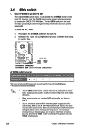
STRIKER II EXTREME CLRTC_SW Enable (Default) Disable STRIKER II EXTREME/ STRIKER II NSE Clear RTC RAM slide switch clr CMOS switch behavior System power state G3* S5... shutdwon function in S0 mode (DOS mode) still works. • Make sure to re-enter your previous BIOS settings after you clear the CMOS. • You do not need to clear the RTC when the system hangs ... data. With the C.P.R. (CPU Parameter Recall) feature, shut down the key during the boot process and enter BIOS setup to clear the system setup information such as system passwords. The clr CMOS switch on the back I /O...
STRIKER II EXTREME CLRTC_SW Enable (Default) Disable STRIKER II EXTREME/ STRIKER II NSE Clear RTC RAM slide switch clr CMOS switch behavior System power state G3* S5... shutdwon function in S0 mode (DOS mode) still works. • Make sure to re-enter your previous BIOS settings after you clear the CMOS. • You do not need to clear the RTC when the system hangs ... data. With the C.P.R. (CPU Parameter Recall) feature, shut down the key during the boot process and enter BIOS setup to clear the system setup information such as system passwords. The clr CMOS switch on the back I /O...
User Manual
Page 57
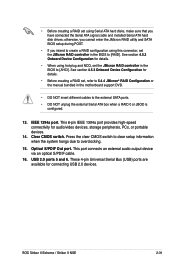
ROG Striker II Extreme / Striker II NSE 2-31 • Before creating a RAID set using Serial ATA hard disks, make sure that you intend to create a RAID configuration using hot-plug and NCQ, set the JMicron RAID controller in the BIOS to [AHCI]. IEEE 1394a port. This 6-pin IEEE 1394a port ... 14. USB 2.0 ports 5 and 6. See section 4.5.3 Onboard Device Configuration for details. • Before creating a RAID set the JMicron RAID controller in the motherboard support DVD. • DO NOT insert different cables to the external SATA ports. • DO NOT unplug the external Serial...
ROG Striker II Extreme / Striker II NSE 2-31 • Before creating a RAID set using Serial ATA hard disks, make sure that you intend to create a RAID configuration using hot-plug and NCQ, set the JMicron RAID controller in the BIOS to [AHCI]. IEEE 1394a port. This 6-pin IEEE 1394a port ... 14. USB 2.0 ports 5 and 6. See section 4.5.3 Onboard Device Configuration for details. • Before creating a RAID set the JMicron RAID controller in the motherboard support DVD. • DO NOT insert different cables to the external SATA ports. • DO NOT unplug the external Serial...
User Manual
Page 59
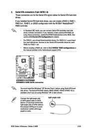
...Striker II Extreme / Striker II NSE 2-33 If you installed Serial ATA hard disk drives, you can connect Serial ATA boot/data hard disk drives to four Serial ATA hard disk drives for each RAID 0 or RAID 1 set. • Before creating a RAID set using these connectors. Use two to these connectors, enable the [RAID Enabled] item in the motherboard... mode, you may connect the right-angle side of SATA signal cable to 5.4.2 NVIDIA® RAID configurations or the manual bundled in the BIOS. Serial ATA connectors (7-pin SATA1-6) These connectors are using Serial ATA hard disk drives.
...Striker II Extreme / Striker II NSE 2-33 If you installed Serial ATA hard disk drives, you can connect Serial ATA boot/data hard disk drives to four Serial ATA hard disk drives for each RAID 0 or RAID 1 set. • Before creating a RAID set using these connectors. Use two to these connectors, enable the [RAID Enabled] item in the motherboard... mode, you may connect the right-angle side of SATA signal cable to 5.4.2 NVIDIA® RAID configurations or the manual bundled in the BIOS. Serial ATA connectors (7-pin SATA1-6) These connectors are using Serial ATA hard disk drives.
User Manual
Page 67
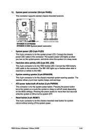
...STRIKER II EXTREME IDE_LED PWRSW RESET * Requires an ATX power supply STRIKER II EXTREME/ STRIKER II NSE System panel connector • System power LED (2-pin PLED) This 2-pin connector is for the system power button. The IDE LED lights up when you to this connector. The speaker allows you turn on the BIOS settings...• System warning speaker (4-pin SPEAKER) This 4-pin connector is for the HDD Activity LED. 12. ROG Striker II Extreme / Striker II NSE 2-41 Connect the HDD Activity LED cable to hear system beeps and warnings. • ATX power button/soft-off the system power...
...STRIKER II EXTREME IDE_LED PWRSW RESET * Requires an ATX power supply STRIKER II EXTREME/ STRIKER II NSE System panel connector • System power LED (2-pin PLED) This 2-pin connector is for the system power button. The IDE LED lights up when you to this connector. The speaker allows you turn on the BIOS settings...• System warning speaker (4-pin SPEAKER) This 4-pin connector is for the HDD Activity LED. 12. ROG Striker II Extreme / Striker II NSE 2-41 Connect the HDD Activity LED cable to hear system beeps and warnings. • ATX power button/soft-off the system power...
User Manual
Page 75
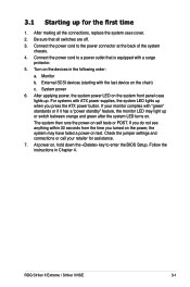
... up. After making all switches are off. 3. After applying power, the system power LED on , hold down the key to enter the BIOS Setup. ROG Striker II Extreme / Striker II NSE 3-1 Monitor b. Turn on self tests or POST. For systems with the last device on . If you do not see anything within 30 ...Connect the power cord to the power connector at the back of the system chassis. 4. 3.1 Starting up for assistance. 7. Check the jumper settings and connections or call your monitor complies with a surge protector. 5. The system then runs the power-on the devices in Chapter 4.
... up. After making all switches are off. 3. After applying power, the system power LED on , hold down the key to enter the BIOS Setup. ROG Striker II Extreme / Striker II NSE 3-1 Monitor b. Turn on self tests or POST. For systems with the last device on . If you do not see anything within 30 ...Connect the power cord to the power connector at the back of the system chassis. 4. 3.1 Starting up for assistance. 7. Check the jumper settings and connections or call your monitor complies with a surge protector. 5. The system then runs the power-on the devices in Chapter 4.
User Manual
Page 87
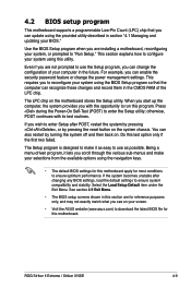
... the system chassis. ROG Striker II Extreme / Striker II NSE 4-9 This section explains how to enter Setup after changing any BIOS settings, load the default settings to use the Setup program, you can change the power management settings. If you wish to ...motherboard stores the Setup utility. 4.2 BIOS setup program This motherboard supports a programmable Low-Pin Count (LPC) chip that the computer can also restart by pressing the reset button on . Use the BIOS Setup program when you are installing a motherboard, reconfiguring your screen. • Visit the ASUS website (www.asus...
... the system chassis. ROG Striker II Extreme / Striker II NSE 4-9 This section explains how to enter Setup after changing any BIOS settings, load the default settings to use the Setup program, you can change the power management settings. If you wish to ...motherboard stores the Setup utility. 4.2 BIOS setup program This motherboard supports a programmable Low-Pin Count (LPC) chip that the computer can also restart by pressing the reset button on . Use the BIOS Setup program when you are installing a motherboard, reconfiguring your screen. • Visit the ASUS website (www.asus...

User Manual
Page 88
... main items: Main For changing the basic system configuration Extreme Tweaker For changing the overclocking settings Advanced For changing the advanced system settings Power For changing the advanced power management (APM) configuration...settings To select an item on the menu bar, press the right or left arrow key on your screen. • Visit the ASUS website (www.asus.com) to download the latest BIOS information. 4-10 Chapter 4: BIOS setup 4.2.1 BIOS menu screen Menu items Menu bar Configuration fields General help Phoenix-AwardBIOS CMOS Setup Utility Extreme...
... main items: Main For changing the basic system configuration Extreme Tweaker For changing the overclocking settings Advanced For changing the advanced system settings Power For changing the advanced power management (APM) configuration...settings To select an item on the menu bar, press the right or left arrow key on your screen. • Visit the ASUS website (www.asus.com) to download the latest BIOS information. 4-10 Chapter 4: BIOS setup 4.2.1 BIOS menu screen Menu items Menu bar Configuration fields General help Phoenix-AwardBIOS CMOS Setup Utility Extreme...

User Manual
Page 93
MEM (DDR), MHz [800] Allows you to set the PCIEX16_3 overclocking frequency. Due to NVIDIA® chipset features, ASUS BIOS will automatically adjust your assigned frequency to an approximate value to adjust the frequency. You can also type the ...) [Auto] Configuration options: [Auto] [5] [6]-[18] ROG Striker II Extreme / Striker II NSE 4-15 PCIE Bus, Slot 3, MHz [100] Allows you to adjust memory frequency. LDT Frequency [5x] Configuration options: [1x] [2x] [3x] [4x] [5x] PCIE Bus, Slot 1 & 2, MHz [100] Allows you set FSB-Memory Clock Mode to [Unlinked]. Use the and keys...
MEM (DDR), MHz [800] Allows you to set the PCIEX16_3 overclocking frequency. Due to NVIDIA® chipset features, ASUS BIOS will automatically adjust your assigned frequency to an approximate value to adjust the frequency. You can also type the ...) [Auto] Configuration options: [Auto] [5] [6]-[18] ROG Striker II Extreme / Striker II NSE 4-15 PCIE Bus, Slot 3, MHz [100] Allows you to adjust memory frequency. LDT Frequency [5x] Configuration options: [1x] [2x] [3x] [4x] [5x] PCIE Bus, Slot 1 & 2, MHz [100] Allows you set FSB-Memory Clock Mode to [Unlinked]. Use the and keys...

User Manual
Page 96
...;���v�] [DDR3_REF+500mv] [DDR3_REF-250mv] [DDR3_REF-500mv] CPU Configuration Extreme Tweaker Phoenix-AwardBIOS CMOS Setup Utility Overclocking Select Menu CPU Type CPU Speed Cache RAM(L2...;←: Select Menu -/+: Change Value Enter: Select SubMenu F5: Setup Defaults F10: Save and Exit 4-18 Chapter 4: BIOS setup CPU GTL_REF0 Ratio [Auto] Configuration options: [Auto] [Default] [+14mV] [+28mV] [+42mV]~[+210mV] [+224mV] ...126mV] DDR3 CHA/B 1/2 Ref Voltage [Auto] Allows you to manually set the memory voltage, or you can set to [Auto] for the safe mode.
...;���v�] [DDR3_REF+500mv] [DDR3_REF-250mv] [DDR3_REF-500mv] CPU Configuration Extreme Tweaker Phoenix-AwardBIOS CMOS Setup Utility Overclocking Select Menu CPU Type CPU Speed Cache RAM(L2...;←: Select Menu -/+: Change Value Enter: Select SubMenu F5: Setup Defaults F10: Save and Exit 4-18 Chapter 4: BIOS setup CPU GTL_REF0 Ratio [Auto] Configuration options: [Auto] [Default] [+14mV] [+28mV] [+42mV]~[+210mV] [+224mV] ...126mV] DDR3 CHA/B 1/2 Ref Voltage [Auto] Allows you to manually set the memory voltage, or you can set to [Auto] for the safe mode.

User Manual
Page 98
... you to set the system date. 4.4.3 Language [English] Allows you an overview of floppy drive installed. 4.4 Main menu When you enter the BIOS Setup program, the Main menu screen appears, giving you to navigate through them. Phoenix-AwardBIOS CMOS Setup Utility Extreme Tweaker Main ...Advanced Power Boot System Time System Date Language Legacy Diskette A: 15 : 30 : 36 Thu, Oct 30 2007 [English] [1.44M, 3.5 in .] 4-20 Chapter 4: BIOS setup Refer to section 4.2.1 BIOS menu screen for information on the menu...
... you to set the system date. 4.4.3 Language [English] Allows you an overview of floppy drive installed. 4.4 Main menu When you enter the BIOS Setup program, the Main menu screen appears, giving you to navigate through them. Phoenix-AwardBIOS CMOS Setup Utility Extreme Tweaker Main ...Advanced Power Boot System Time System Date Language Legacy Diskette A: 15 : 30 : 36 Thu, Oct 30 2007 [English] [1.44M, 3.5 in .] 4-20 Chapter 4: BIOS setup Refer to section 4.2.1 BIOS menu screen for information on the menu...

User Manual
Page 99
... Menu PIO Mode UDMA Mode Primary IDE Master Access Mode Capacity [Auto] [Auto] [Auto] [Auto] 0 MB Item Specific Help Set a PIO mode for the IDE device. Configuration options: [Disable] [Auto] Primary IDE Master/Slave [Auto] Select [Auto] to ...is a separate sub-menu for the remaining fields on a previous system, the setup BIOS may detect incorrect parameters. Configuration options: [Auto] [Mode 0] [Mode 1] [Mode 2] [Mode 3] [Mode 4] UDMA Mode [Auto] Disables or sets the UDMA mode. Configuration options: [None] [Auto] [Manual] ROG Striker II Extreme / Striker II NSE 4-21
... Menu PIO Mode UDMA Mode Primary IDE Master Access Mode Capacity [Auto] [Auto] [Auto] [Auto] 0 MB Item Specific Help Set a PIO mode for the IDE device. Configuration options: [Disable] [Auto] Primary IDE Master/Slave [Auto] Select [Auto] to ...is a separate sub-menu for the remaining fields on a previous system, the setup BIOS may detect incorrect parameters. Configuration options: [Auto] [Mode 0] [Mode 1] [Mode 2] [Mode 3] [Mode 4] UDMA Mode [Auto] Disables or sets the UDMA mode. Configuration options: [None] [Auto] [Manual] ROG Striker II Extreme / Striker II NSE 4-21
User Manual
Page 101
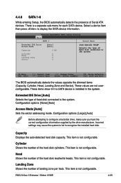
... Configuration options: [None] [Auto] Access Mode [Auto] Sets the sector addressing mode. This item is installed in the system. Head Shows the number of fixed disk connected to the system. ROG Striker II Extreme / Striker II NSE 4-23 Phoenix-AwardBIOS CMOS Setup Utility Main SATA 1 Select ...8595; : Select Item →←: Select Menu -/+: Change Value Enter: Select SubMenu F5: Setup Defaults F10: Save and Exit The BIOS automatically detects the values opposite the dimmed items (Capacity, Cylinder, Head, Landing Zone and Sector). Select a device item then press to ...
... Configuration options: [None] [Auto] Access Mode [Auto] Sets the sector addressing mode. This item is installed in the system. Head Shows the number of fixed disk connected to the system. ROG Striker II Extreme / Striker II NSE 4-23 Phoenix-AwardBIOS CMOS Setup Utility Main SATA 1 Select ...8595; : Select Item →←: Select Menu -/+: Change Value Enter: Select SubMenu F5: Setup Defaults F10: Save and Exit The BIOS automatically detects the values opposite the dimmed items (Capacity, Cylinder, Head, Landing Zone and Sector). Select a device item then press to ...

User Manual
Page 111
.... It also allows you to disable the Power On by the BIOS. Phoenix-AwardBIOS CMOS Setup Utility Power Hardware Monitor Select Menu Voltage Monitor Temperature... monitor values automatically detected by PS/2 keyboard function or set the time of alarm: 1. Alarm Time (hh:mm) [ X: X: X] To set specific keys on the PS/2 keyboard to display a pop...;←: Select Menu -/+: Change Value Enter: Select SubMenu F5: Setup Defaults F10: Save and Exit ROG Striker II Extreme / Striker II NSE 4-33 Configuration options: [Disabled] [Space Bar] [Ctrl-ESC] [Power Key] 4.6.4 Hardware Monitor The items...
.... It also allows you to disable the Power On by the BIOS. Phoenix-AwardBIOS CMOS Setup Utility Power Hardware Monitor Select Menu Voltage Monitor Temperature... monitor values automatically detected by PS/2 keyboard function or set the time of alarm: 1. Alarm Time (hh:mm) [ X: X: X] To set specific keys on the PS/2 keyboard to display a pop...;←: Select Menu -/+: Change Value Enter: Select SubMenu F5: Setup Defaults F10: Save and Exit ROG Striker II Extreme / Striker II NSE 4-33 Configuration options: [Disabled] [Space Bar] [Ctrl-ESC] [Power Key] 4.6.4 Hardware Monitor The items...
User Manual
Page 117
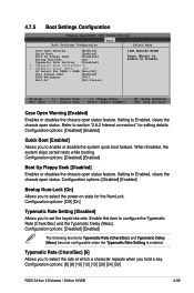
...Extreme Tweaker Advanced Power Boot Tools Boot Settings Configuration Exit Select Menu Case Open Warning [Enabled] Quick Boot [Enabled] Boot Up Floppy Seek [Disabled] Bootup Num-Lock [On] Typematic Rate Setting [Disabled] x Typematic Rate (Chars/Sec) 6 x Typematic Delay (Msec) 250 OS Select For DRAM > 64MB [Non-OS2] Full Screen LOGO [Enabled] BIOS...Msec) become configurable when the Typematic Rate Setting is enabled. Configuration options: [6] [8] [10] [12] [15] [20] [24] [30] ROG Striker II Extreme / Striker II NSE 4-39 Setting to set the keystroke rate. When Enabled, the ...
...Extreme Tweaker Advanced Power Boot Tools Boot Settings Configuration Exit Select Menu Case Open Warning [Enabled] Quick Boot [Enabled] Boot Up Floppy Seek [Disabled] Bootup Num-Lock [On] Typematic Rate Setting [Disabled] x Typematic Rate (Chars/Sec) 6 x Typematic Delay (Msec) 250 OS Select For DRAM > 64MB [Non-OS2] Full Screen LOGO [Enabled] BIOS...Msec) become configurable when the Typematic Rate Setting is enabled. Configuration options: [6] [8] [10] [12] [15] [20] [24] [30] ROG Striker II Extreme / Striker II NSE 4-39 Setting to set the keystroke rate. When Enabled, the ...

User Manual
Page 118
... is set to [Enabled] if you are running on an OS/2 operating system with an installed RAM of the BIOS wallpaper. Configuration options: [All Errors] [No Errors] [All, But Keyboard] [All, But Diskette] [All, But Disk/Key] 4.7.6 Security Main Phoenix-AwardBIOS CMOS Setup Utility Extreme Tweaker ...] [750] [1000] OS Select for DRAM > 64MB [Non-OS2] Set this item to OS2 only when you want to use the ASUS MyLogo3™ feature. Configuration options: [Non-OS2] [OS2] Full Screen LOGO [Enabled] Allows you to set the delay before keystrokes begin to repeat. Configuration options: [00%] [25...
... is set to [Enabled] if you are running on an OS/2 operating system with an installed RAM of the BIOS wallpaper. Configuration options: [All Errors] [No Errors] [All, But Keyboard] [All, But Diskette] [All, But Disk/Key] 4.7.6 Security Main Phoenix-AwardBIOS CMOS Setup Utility Extreme Tweaker ...] [750] [1000] OS Select for DRAM > 64MB [Non-OS2] Set this item to OS2 only when you want to use the ASUS MyLogo3™ feature. Configuration options: [Non-OS2] [OS2] Full Screen LOGO [Enabled] Allows you to set the delay before keystrokes begin to repeat. Configuration options: [00%] [25...

User Manual
Page 119
...to section "2.6 Jumper" for instructions. The following message appears: PASSWORD DISABLED !!! The password field setting is required to enter the BIOS Setup program preventing unauthorized access. The User password is changed to Clear. If you forget your ... Select [Setup] to require the password before entering the system. Configuration options: [Setup] [System] ROG Striker II Extreme / Striker II NSE 4-41 Password Check This field requires you to set passwords: To set a password: 1. Type in a password using a combination of a maximum of eight (8) alpha‑numeric...
...to section "2.6 Jumper" for instructions. The following message appears: PASSWORD DISABLED !!! The password field setting is required to enter the BIOS Setup program preventing unauthorized access. The User password is changed to Clear. If you forget your ... Select [Setup] to require the password before entering the system. Configuration options: [Setup] [System] ROG Striker II Extreme / Striker II NSE 4-41 Password Check This field requires you to set passwords: To set a password: 1. Type in a password using a combination of a maximum of eight (8) alpha‑numeric...

User Manual
Page 120
... [Enter] to select Load BIOS Profile Phoenix-AwardBIOS CMOS Setup Utility Main Extreme Tweaker Advanced Power Boot Tools Exit Load BIOS Profile Select Menu Load from Profile 1 Load from Profile 2 Load from File Item Specific Help Load BIOS Profile from Profile 1/2 Allows you to load the previous BIOS settings saved in the BIOS Flash. Load from Profile...
... [Enter] to select Load BIOS Profile Phoenix-AwardBIOS CMOS Setup Utility Main Extreme Tweaker Advanced Power Boot Tools Exit Load BIOS Profile Select Menu Load from Profile 1 Load from Profile 2 Load from File Item Specific Help Load BIOS Profile from Profile 1/2 Allows you to load the previous BIOS settings saved in the BIOS Flash. Load from Profile...

User Manual
Page 135
... then click Next. 3. 5.3 Software information Most of your boot logo. ROG Striker II Extreme / Striker II NSE 5-9 To launch the ASUS MyLogo3 1. From the left window pane, select the folder that the BIOS item Full Screen Logo is the image that will conveniently guide you intend to ... the option Launch MyLogo to use ASUS MyLogo3™. When prompted, locate the new BIOS file, then click Next. See section 4.1.3 Updating the BIOS. • Make sure that contains the image you through the installation. See section 4.7.5 Boot Settings Configuration. • You can create...
... then click Next. 3. 5.3 Software information Most of your boot logo. ROG Striker II Extreme / Striker II NSE 5-9 To launch the ASUS MyLogo3 1. From the left window pane, select the folder that the BIOS item Full Screen Logo is the image that will conveniently guide you intend to ... the option Launch MyLogo to use ASUS MyLogo3™. When prompted, locate the new BIOS file, then click Next. See section 4.1.3 Updating the BIOS. • Make sure that contains the image you through the installation. See section 4.7.5 Boot Settings Configuration. • You can create...


