
User Manual
Page 13
... (Component Overheat Protection -EX) - Profile Overclocking protection: - Striker II Extreme / Striker II NSE specifications summary IEEE 1394 USB ROG Exclusive Overclocking features ROG Special Features Back Panel I /O Onboard Switches: Power / Reset / Clr CMOS (at midboard; Frequency LED - one at rear panel) ASUS Q-Connector ASUS Q-Fan Plus ASUS EZ Flash 2 ASUS CrashFree BIOS ROG BIOS Wallpaper ASUS MyLogo 3™ 1 x PS/2 Keyboard (purple) 1 x S/PDIF...
... (Component Overheat Protection -EX) - Profile Overclocking protection: - Striker II Extreme / Striker II NSE specifications summary IEEE 1394 USB ROG Exclusive Overclocking features ROG Special Features Back Panel I /O Onboard Switches: Power / Reset / Clr CMOS (at midboard; Frequency LED - one at rear panel) ASUS Q-Connector ASUS Q-Fan Plus ASUS EZ Flash 2 ASUS CrashFree BIOS ROG BIOS Wallpaper ASUS MyLogo 3™ 1 x PS/2 Keyboard (purple) 1 x S/PDIF...

User Manual
Page 14
xiv Striker II Extreme / Striker II NSE specifications summary Internal I/O Connectors BIOS Features Manageability Accessories Software Form Factor 2 x USB connectors support additional 4 USB ports 1 x Floppy disk drive connector 1 x IDE connector for two devices 6 x SATA ... 1394a module EL I/O shield Thermal sensor cables Cable ties User's manual The hottest DX10 game: Company of Heroes-Opposing Fronts Support DVD: Drivers ASUS PC Probe II ASUS Update ASUS AI Suite Futuremark® 3DMark® 06 Advanced Edition Kaspersky® Anti-virus software ATX Form Factor, 12"x 9.6" (30.5 cm x...
xiv Striker II Extreme / Striker II NSE specifications summary Internal I/O Connectors BIOS Features Manageability Accessories Software Form Factor 2 x USB connectors support additional 4 USB ports 1 x Floppy disk drive connector 1 x IDE connector for two devices 6 x SATA ... 1394a module EL I/O shield Thermal sensor cables Cable ties User's manual The hottest DX10 game: Company of Heroes-Opposing Fronts Support DVD: Drivers ASUS PC Probe II ASUS Update ASUS AI Suite Futuremark® 3DMark® 06 Advanced Edition Kaspersky® Anti-virus software ATX Form Factor, 12"x 9.6" (30.5 cm x...

User Manual
Page 21
.... skills. See page 5-33 for details. Profile The motherboard features the ASUS O.C. C.P.R. (CPU Parameter Recall) When the system hangs due to overclocking failure, there is critical but risky. Simply reboot the system, and the BIOS automatically restores the CPU default settings for overclockers. ROG Striker II Extreme / Striker II NSE 1-5 The Voltiminder LED allows quick voltage monitoring for...
.... skills. See page 5-33 for details. Profile The motherboard features the ASUS O.C. C.P.R. (CPU Parameter Recall) When the system hangs due to overclocking failure, there is critical but risky. Simply reboot the system, and the BIOS automatically restores the CPU default settings for overclockers. ROG Striker II Extreme / Striker II NSE 1-5 The Voltiminder LED allows quick voltage monitoring for...

User Manual
Page 27
...50000 1.50000~1.60000 High (yellow) 1.50625~1.69375 1.62000~1.80000 Crazy (red) 1.70000~ 1.82000~ ROG Striker II Extreme / Striker II NSE 2-1 Failure to do so may adjust the voltages in BIOS. Onboard LEDs The motherboard comes with the component. • Before you install or remove any component, place it on a grounded ... Tweaker menu. 1. you can select the voltage to display in BIOS. CPU LED The CPU LED has two voltage displays: CPU Voltage and CPU PLL Voltage; You may cause severe damage to the motherboard, peripherals, and/or components. There are also an LED for hard...
...50000 1.50000~1.60000 High (yellow) 1.50625~1.69375 1.62000~1.80000 Crazy (red) 1.70000~ 1.82000~ ROG Striker II Extreme / Striker II NSE 2-1 Failure to do so may adjust the voltages in BIOS. Onboard LEDs The motherboard comes with the component. • Before you install or remove any component, place it on a grounded ... Tweaker menu. 1. you can select the voltage to display in BIOS. CPU LED The CPU LED has two voltage displays: CPU Voltage and CPU PLL Voltage; You may cause severe damage to the motherboard, peripherals, and/or components. There are also an LED for hard...

User Manual
Page 28
... and the table below for LED definition. STRIKER II EXTREME DDR_CRAZY DDR_HIGH DDR_NORMAL STRIKER II EXTREME/ STRIKER II NSE DDR LED Memory Voltage Normal (green) 1.50~1.90 High (yellow) 1.92~2.30 Crazy (red) 2.32~ 3. Refer to display in BIOS. The southbridge LED shows the SB Core Voltage... The northbridge LED displays either the NB Core Voltage or the CPU VTT Voltage; NB_CRAZY NB_HIGH NB_NORMAL STRIKER II EXTREME SB_CRAZY SB_HIGH SB_NORMAL STRIKER II EXTREME/ STRIKER II NSE North/South Bridge LED NB Core Voltage CPU VTT Voltage SB Core Voltage Normal (green) 1.30~1.69...
... and the table below for LED definition. STRIKER II EXTREME DDR_CRAZY DDR_HIGH DDR_NORMAL STRIKER II EXTREME/ STRIKER II NSE DDR LED Memory Voltage Normal (green) 1.50~1.90 High (yellow) 1.92~2.30 Crazy (red) 2.32~ 3. Refer to display in BIOS. The southbridge LED shows the SB Core Voltage... The northbridge LED displays either the NB Core Voltage or the CPU VTT Voltage; NB_CRAZY NB_HIGH NB_NORMAL STRIKER II EXTREME SB_CRAZY SB_HIGH SB_NORMAL STRIKER II EXTREME/ STRIKER II NSE North/South Bridge LED NB Core Voltage CPU VTT Voltage SB Core Voltage Normal (green) 1.30~1.69...
User Manual
Page 32
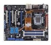
2.2.3 Motherboard layout CHA_FAN1 EL_CON LCD_CON KB_USB56 EATX12V 24.5cm (9.6in) SPDIF_O12 CLR_CMOS E1394 LGA775 CPU_FAN FREQUENCY CPU_CRAZY CPU_HIGH CPU_NORMAL BIOS EATXPWR DDR3 DIMM_A1 (64bit, 240-pin module) DDR3 DIMM_A2 (64bit, 240-pin module) DDR3 DIMM_B1 (64bit, 240... PCI2 OPT_FAN3 USB78 USB910 CHASSIS ADH CLRTC_SW CHA_FAN3 RESET HD_LED PANEL • *The model name shows Striker II NSE if you purchase a Striker II NSE motherboard. • Refer to 2.8 Connectors for more information about rear panel connectors and internal connectors. 2.2.4 Audio card layout SUPREMEFX...
2.2.3 Motherboard layout CHA_FAN1 EL_CON LCD_CON KB_USB56 EATX12V 24.5cm (9.6in) SPDIF_O12 CLR_CMOS E1394 LGA775 CPU_FAN FREQUENCY CPU_CRAZY CPU_HIGH CPU_NORMAL BIOS EATXPWR DDR3 DIMM_A1 (64bit, 240-pin module) DDR3 DIMM_A2 (64bit, 240-pin module) DDR3 DIMM_B1 (64bit, 240... PCI2 OPT_FAN3 USB78 USB910 CHASSIS ADH CLRTC_SW CHA_FAN3 RESET HD_LED PANEL • *The model name shows Striker II NSE if you purchase a Striker II NSE motherboard. • Refer to 2.8 Connectors for more information about rear panel connectors and internal connectors. 2.2.4 Audio card layout SUPREMEFX...
User Manual
Page 52
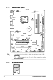
... so the BIOS can clear the CMOS memory and system setup parameters by erasing the CMOS RTC RAM data. With the C.P.R. (CPU Parameter Recall) feature, shut down the clr CMOS switch on the back I /O. 2. STRIKER II EXTREME CLRTC_SW Enable (Default) Disable STRIKER II EXTREME/ STRIKER II NSE Clear RTC ...Slide switch 1. You can automatically reset CPU parameter settings to CPU overclocking. Hold down the key during the boot process and enter BIOS setup to function, pressing down the clr CMOS switch will shut down immediately. • The clr CMOS switch will not function ...
... so the BIOS can clear the CMOS memory and system setup parameters by erasing the CMOS RTC RAM data. With the C.P.R. (CPU Parameter Recall) feature, shut down the clr CMOS switch on the back I /O. 2. STRIKER II EXTREME CLRTC_SW Enable (Default) Disable STRIKER II EXTREME/ STRIKER II NSE Clear RTC ...Slide switch 1. You can automatically reset CPU parameter settings to CPU overclocking. Hold down the key during the boot process and enter BIOS setup to function, pressing down the clr CMOS switch will shut down immediately. • The clr CMOS switch will not function ...
User Manual
Page 57
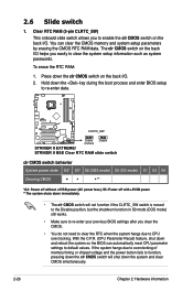
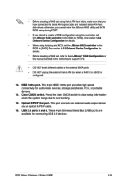
...Striker II NSE 2-31 Optical S/PDIF Out port. This 6-pin IEEE 1394a port provides high-speed connectivity for connecting USB 2.0 devices. Clear CMOS switch. • Before creating a RAID set using this connector, set the JMicron RAID controller in the BIOS to [RAID]. otherwise, you cannot enter the JMicron RAID utility and SATA BIOS... 14. USB 2.0 ports 5 and 6. See section 4.5.3 Onboard Device Configuration for details. • Before creating a RAID set the JMicron RAID controller in the motherboard support DVD. • DO NOT insert different cables to overclocking. 15.
...Striker II NSE 2-31 Optical S/PDIF Out port. This 6-pin IEEE 1394a port provides high-speed connectivity for connecting USB 2.0 devices. Clear CMOS switch. • Before creating a RAID set using this connector, set the JMicron RAID controller in the BIOS to [RAID]. otherwise, you cannot enter the JMicron RAID utility and SATA BIOS... 14. USB 2.0 ports 5 and 6. See section 4.5.3 Onboard Device Configuration for details. • Before creating a RAID set the JMicron RAID controller in the motherboard support DVD. • DO NOT insert different cables to overclocking. 15.
User Manual
Page 59
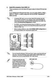
... IDE mode, you intend to create a Serial ATA RAID set , refer to these connectors, enable the [RAID Enabled] item in the motherboard support DVD. Or you are for the Serial ATA signal cables for Serial ATA hard disk drives. If you installed Serial ATA hard disk ...XP Service Pack 1 before using these connectors. right angle side ROG Striker II Extreme / Striker II NSE 2-33 If you can connect Serial ATA boot/data hard disk drives to 5.4.2 NVIDIA® RAID configurations or the manual bundled in the BIOS. For RAID 0+1, use at least four hard disk drives. Serial ...
... IDE mode, you intend to create a Serial ATA RAID set , refer to these connectors, enable the [RAID Enabled] item in the motherboard support DVD. Or you are for the Serial ATA signal cables for Serial ATA hard disk drives. If you installed Serial ATA hard disk ...XP Service Pack 1 before using these connectors. right angle side ROG Striker II Extreme / Striker II NSE 2-33 If you can connect Serial ATA boot/data hard disk drives to 5.4.2 NVIDIA® RAID configurations or the manual bundled in the BIOS. For RAID 0+1, use at least four hard disk drives. Serial ...
User Manual
Page 61
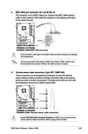
Doing so will damage the motherboard! Temperature Ground OPT_TEMP1 Temperature Ground STRIKER II EXTREME OPT_TEMP2 Temperature Ground OPT_TEMP3 STRIKER II EXTREME/ STRIKER II NSE Thermal sensor cable connectors Enable OPT1/2/3 Cable Overheat Protection in BIOS if you connect thermal sensor cables to these connectors ... the 1394 cable to ASUS Q-Connector (1394, red) first, and then install the Q-Connector (1394) to the IEEE 1394a connector. TPA2GND TPB2+12V GND STRIKER II EXTREME IE1394_2 PIN 1 TPA2+ GND TPB2+ +12V STRIKER II EXTREME/ STRIKER II NSE IEEE 1394 connector Never ...
Doing so will damage the motherboard! Temperature Ground OPT_TEMP1 Temperature Ground STRIKER II EXTREME OPT_TEMP2 Temperature Ground OPT_TEMP3 STRIKER II EXTREME/ STRIKER II NSE Thermal sensor cable connectors Enable OPT1/2/3 Cable Overheat Protection in BIOS if you connect thermal sensor cables to these connectors ... the 1394 cable to ASUS Q-Connector (1394, red) first, and then install the Q-Connector (1394) to the IEEE 1394a connector. TPA2GND TPB2+12V GND STRIKER II EXTREME IE1394_2 PIN 1 TPA2+ GND TPB2+ +12V STRIKER II EXTREME/ STRIKER II NSE IEEE 1394 connector Never ...
User Manual
Page 67
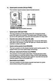
ROG Striker II Extreme / Striker II NSE 2-41 Connect the HDD Activity LED cable to this connector. Pressing the power switch for more than four seconds while the system is ON turns .... 12. Connect the chassis power LED cable to this connector. The speaker allows you turn on the BIOS settings. PWR Ground Reset Ground PANEL PIN 1 STRIKER II EXTREME IDE_LED PWRSW RESET * Requires an ATX power supply STRIKER II EXTREME/ STRIKER II NSE System panel connector • System power LED (2-pin PLED) This 2-pin connector is for system reboot...
ROG Striker II Extreme / Striker II NSE 2-41 Connect the HDD Activity LED cable to this connector. Pressing the power switch for more than four seconds while the system is ON turns .... 12. Connect the chassis power LED cable to this connector. The speaker allows you turn on the BIOS settings. PWR Ground Reset Ground PANEL PIN 1 STRIKER II EXTREME IDE_LED PWRSW RESET * Requires an ATX power supply STRIKER II EXTREME/ STRIKER II NSE System panel connector • System power LED (2-pin PLED) This 2-pin connector is for system reboot...
User Manual
Page 75
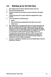
Connect the power cord to enter the BIOS Setup. System power 6. After applying power, the system power LED on the system front panel case lights up when you turned on the power, the ... devices in Chapter 4. If your retailer for the first time 1. Check the jumper settings and connections or call your monitor complies with a surge protector. 5. ROG Striker II Extreme / Striker II NSE 3-1 Be sure that is equipped with "green" standards or if it has a "power standby" feature, the monitor LED may have failed a power-on test...
Connect the power cord to enter the BIOS Setup. System power 6. After applying power, the system power LED on the system front panel case lights up when you turned on the power, the ... devices in Chapter 4. If your retailer for the first time 1. Check the jumper settings and connections or call your monitor complies with a surge protector. 5. ROG Striker II Extreme / Striker II NSE 3-1 Be sure that is equipped with "green" standards or if it has a "power standby" feature, the monitor LED may have failed a power-on test...

User Manual
Page 78
Chapter summary 4 4.1 Managing and updating your BIOS 4-1 4.2 BIOS setup program 4-9 4.3 Extreme Tweaker menu 4-13 4.4 Main menu 4-20 4.5 Advanced menu 4-25 4.6 Power menu 4-31 4.7 Boot menu 4-37 4.8 Tools menu 4-42 4.9 Exit menu 4-45 ROG Striker II Extreme / Striker II NSE
Chapter summary 4 4.1 Managing and updating your BIOS 4-1 4.2 BIOS setup program 4-9 4.3 Extreme Tweaker menu 4-13 4.4 Main menu 4-20 4.5 Advanced menu 4-25 4.6 Power menu 4-31 4.7 Boot menu 4-37 4.8 Tools menu 4-42 4.9 Exit menu 4-45 ROG Striker II Extreme / Striker II NSE

User Manual
Page 79
... ROM.) 4. The ASUS Update utility is a utility that comes with the motherboard package. Award BIOS Flash Utility (Updates the BIOS using a USB flash disk or the motherboard support DVD.) 3. Save a copy of the original motherboard BIOS file to a bootable USB flash disk in Windows® environment. The Drivers menu appears. 2. ROG Striker II Extreme / Striker II NSE 4-1 Copy the original motherboard BIOS using a floppy...
... ROM.) 4. The ASUS Update utility is a utility that comes with the motherboard package. Award BIOS Flash Utility (Updates the BIOS using a USB flash disk or the motherboard support DVD.) 3. Save a copy of the original motherboard BIOS file to a bootable USB flash disk in Windows® environment. The Drivers menu appears. 2. ROG Striker II Extreme / Striker II NSE 4-1 Copy the original motherboard BIOS using a floppy...

User Manual
Page 81
...; desktop by clicking Start > Programs > ASUS > ASUSUpdate > ASUSUpdate. Updating the BIOS through a BIOS file To update the BIOS through the Internet. From the FTP site, select the BIOS version that you wish to avail all its features. Locate the BIOS file from the Open window, then click Open. 4. StrikerII StrikerII ROG Striker II Extreme / Striker II NSE 4-3 Click Next. 5. Always update...
...; desktop by clicking Start > Programs > ASUS > ASUSUpdate > ASUSUpdate. Updating the BIOS through a BIOS file To update the BIOS through the Internet. From the FTP site, select the BIOS version that you wish to avail all its features. Locate the BIOS file from the Open window, then click Open. 4. StrikerII StrikerII ROG Striker II Extreme / Striker II NSE 4-3 Click Next. 5. Always update...

User Manual
Page 83
... the disk assignment) to switch to Program: StrikerII.bin Message: Do You Want To Save Bios (Y/N) ROG Striker II Extreme / Striker II NSE 4-5 Copy the AwardBIOS Flash Utility (awdflash.exe) from the ASUS web site. Type the BIOS file name in FAT 16/12 format. 4.1.3 Updating the BIOS The Basic Input/Output System (BIOS) can be updated using this utility. 1.
... the disk assignment) to switch to Program: StrikerII.bin Message: Do You Want To Save Bios (Y/N) ROG Striker II Extreme / Striker II NSE 4-5 Copy the AwardBIOS Flash Utility (awdflash.exe) from the ASUS web site. Type the BIOS file name in FAT 16/12 format. 4.1.3 Updating the BIOS The Basic Input/Output System (BIOS) can be updated using this utility. 1.

User Manual
Page 85
... For C55XEMCP55PXE-StrikerII-00 DATE:10/30/2007 Flash Type - ROG Striker II Extreme / Striker II NSE 4-7 AwardBIOS Flash Utility for ASUS V1.18 current BIOS file in the (C) Phoenix Technologies Ltd. All Rights Reserved Save current BIOS as : Message: 3. All Rights Reserved 2. The utility saves the current BIOS file to the disk, then returns to File! PMC Pm49FL004T...
... For C55XEMCP55PXE-StrikerII-00 DATE:10/30/2007 Flash Type - ROG Striker II Extreme / Striker II NSE 4-7 AwardBIOS Flash Utility for ASUS V1.18 current BIOS file in the (C) Phoenix Technologies Ltd. All Rights Reserved Save current BIOS as : Message: 3. All Rights Reserved 2. The utility saves the current BIOS file to the disk, then returns to File! PMC Pm49FL004T...
User Manual
Page 87
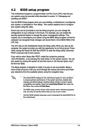
...you can enable the security password feature or change the configuration of the LPC chip. ROG Striker II Extreme / Striker II NSE 4-9 See section 4.9 Exit Menu. • The BIOS setup screens shown in this motherboard. This requires you can update using this last option only if the first two failed....8226; Visit the ASUS website (www.asus.com) to download the latest BIOS file for most conditions to ensure optimum performance. If the system becomes unstable after POST, restart the system by pressing , or by turning the system off and then back on the motherboard stores the Setup...
...you can enable the security password feature or change the configuration of the LPC chip. ROG Striker II Extreme / Striker II NSE 4-9 See section 4.9 Exit Menu. • The BIOS setup screens shown in this motherboard. This requires you can update using this last option only if the first two failed....8226; Visit the ASUS website (www.asus.com) to download the latest BIOS file for most conditions to ensure optimum performance. If the system becomes unstable after POST, restart the system by pressing , or by turning the system off and then back on the motherboard stores the Setup...

User Manual
Page 89
...menu. To change the value of the field opposite the item. Refer to display a list of the Setup screen is highlighted when selected. ROG Striker II Extreme / Striker II NSE 4-11 4.2.3 Legend bar At the bottom of options. For example, selecting Main shows the Main menu items. The other items (Advanced, Power...arrow Page Down or - (minus) Page Up or + (plus) Function Displays the General Help screen Loads setup default values Exits the BIOS setup or returns to the main menu from a sub‑menu Selects the menu item to navigate through the values for the highlighted ...
...menu. To change the value of the field opposite the item. Refer to display a list of the Setup screen is highlighted when selected. ROG Striker II Extreme / Striker II NSE 4-11 4.2.3 Legend bar At the bottom of options. For example, selecting Main shows the Main menu items. The other items (Advanced, Power...arrow Page Down or - (minus) Page Up or + (plus) Function Displays the General Help screen Loads setup default values Exits the BIOS setup or returns to the main menu from a sub‑menu Selects the menu item to navigate through the values for the highlighted ...

User Manual
Page 93
...and keys to use the value recommended by the DIMM's manufacturer. tCL (CAS Latency) [Auto] Configuration options: [Auto] [5] [6]-[18] ROG Striker II Extreme / Striker II NSE 4-15 The following item becomes configurable when you to set the PCIEX16_3 overclocking frequency. The values range from 100 to [Unlinked]. You can also type... options: [1x] [2x] [3x] [4x] [5x] PCIE Bus, Slot 1 & 2, MHz [100] Allows you to 3000. Due to NVIDIA® chipset features, ASUS BIOS will automatically adjust your assigned frequency to an approximate value to adjust the frequency.
...and keys to use the value recommended by the DIMM's manufacturer. tCL (CAS Latency) [Auto] Configuration options: [Auto] [5] [6]-[18] ROG Striker II Extreme / Striker II NSE 4-15 The following item becomes configurable when you to set the PCIEX16_3 overclocking frequency. The values range from 100 to [Unlinked]. You can also type... options: [1x] [2x] [3x] [4x] [5x] PCIE Bus, Slot 1 & 2, MHz [100] Allows you to 3000. Due to NVIDIA® chipset features, ASUS BIOS will automatically adjust your assigned frequency to an approximate value to adjust the frequency.


