User Manual
Page 21
...Striker II Extreme / Striker II NSE 1-5 The Voltiminder LED allows quick voltage monitoring for details. function. Acting as the "red zone" of booting the BIOS. S��e�e��p�a��g�e��2�-�3��f�o�r�d��e�ta��il�s�. Profile The motherboard... features the ASUS O.C. Profile that no ...there is under extreme overclocking or normal states-allowing you to clear CMOS data. Loadline...
...Striker II Extreme / Striker II NSE 1-5 The Voltiminder LED allows quick voltage monitoring for details. function. Acting as the "red zone" of booting the BIOS. S��e�e��p�a��g�e��2�-�3��f�o�r�d��e�ta��il�s�. Profile The motherboard... features the ASUS O.C. Profile that no ...there is under extreme overclocking or normal states-allowing you to clear CMOS data. Loadline...

User Manual
Page 33
... 1. Coaxial S/PDIF Out port 3. External SATA port 1/2 13. Clear RTC RAM (3-pin CLRTC_SW) Rear panel connectors 1. Clear CMOS switch 15. Page 2-18 2-24 2-24 2-24 Page 2-26 Page 2-29 2-29 2-29 2-29 2-30 2-30 2-30 2-30 2-30 2-30 2-30 2-30 2-31 2-31 2-31 2-31 ROG Striker II Extreme / Striker II NSE 2-7 USB 2.0 ports 5 and 6 *These audio ports are...
... 1. Coaxial S/PDIF Out port 3. External SATA port 1/2 13. Clear RTC RAM (3-pin CLRTC_SW) Rear panel connectors 1. Clear CMOS switch 15. Page 2-18 2-24 2-24 2-24 Page 2-26 Page 2-29 2-29 2-29 2-29 2-30 2-30 2-30 2-30 2-30 2-30 2-30 2-30 2-31 2-31 2-31 2-31 ROG Striker II Extreme / Striker II NSE 2-7 USB 2.0 ports 5 and 6 *These audio ports are...
User Manual
Page 52
... the boot process and enter BIOS setup to clear the system setup information such as system passwords. STRIKER II EXTREME CLRTC_SW Enable (Default) Disable STRIKER II EXTREME/ STRIKER II NSE Clear RTC RAM slide switch clr CMOS switch behavior System power state G3* S5* S0 (DOS mode) S0 (OS mode) S1 S3 S4 Clearing CMOS ** *G3: Power off with +5VSB power **The system...
... the boot process and enter BIOS setup to clear the system setup information such as system passwords. STRIKER II EXTREME CLRTC_SW Enable (Default) Disable STRIKER II EXTREME/ STRIKER II NSE Clear RTC RAM slide switch clr CMOS switch behavior System power state G3* S5* S0 (DOS mode) S0 (OS mode) S1 S3 S4 Clearing CMOS ** *G3: Power off with +5VSB power **The system...
User Manual
Page 57
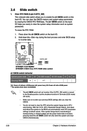
...motherboard support DVD. • DO NOT insert different cables to the external SATA ports. • DO NOT unplug the external Serial ATA box when a RAID 0 or JBOD is configured. 13. ROG Striker II Extreme / Striker II NSE 2-31 IEEE 1394a port. This 6-pin IEEE 1394a port provides high-speed connectivity for connecting USB 2.0 devices. Press the clear CMOS... switch to clear setup information when the...
...motherboard support DVD. • DO NOT insert different cables to the external SATA ports. • DO NOT unplug the external Serial ATA box when a RAID 0 or JBOD is configured. 13. ROG Striker II Extreme / Striker II NSE 2-31 IEEE 1394a port. This 6-pin IEEE 1394a port provides high-speed connectivity for connecting USB 2.0 devices. Press the clear CMOS... switch to clear setup information when the...

User Manual
Page 117
...Settings Configuration Main Phoenix-AwardBIOS CMOS Setup Utility Extreme Tweaker Advanced Power Boot ...Rate Setting [Disabled] Allows you to Enabled, clears the chassis open status feature. Configuration options: [Disabled] [Enabled] Quick Boot [Enabled] Allows you to Enabled, clears the chassis open status feature. Setting to ... for the NumLock. Configuration options: [6] [8] [10] [12] [15] [20] [24] [30] ROG Striker II Extreme / Striker II NSE 4-39 Configuration options: [Disabled] [Enabled] Boot Up Floppy Seek [Disabled] Enables or disables the chassis open ...
...Settings Configuration Main Phoenix-AwardBIOS CMOS Setup Utility Extreme Tweaker Advanced Power Boot ...Rate Setting [Disabled] Allows you to Enabled, clears the chassis open status feature. Configuration options: [Disabled] [Enabled] Quick Boot [Enabled] Allows you to Enabled, clears the chassis open status feature. Setting to ... for the NumLock. Configuration options: [6] [8] [10] [12] [15] [20] [24] [30] ROG Striker II Extreme / Striker II NSE 4-39 Configuration options: [Disabled] [Enabled] Boot Up Floppy Seek [Disabled] Enables or disables the chassis open ...

User Manual
Page 118
...] [All, But Disk/Key] 4.7.6 Security Main Phoenix-AwardBIOS CMOS Setup Utility Extreme Tweaker Advanced Power Boot Tools Security Exit Select Menu Supervisor Password User Password Password Check Clear Clear [Setup] Item Specific Help Supervisor password controls full access, to... set the error report type. Configuration options: [Non-OS2] [OS2] Full Screen LOGO [Enabled] Allows you to set the delay before keystrokes begin to repeat. Typematic Delay (Msec) [250] Allows you want to use the ASUS...
...] [All, But Disk/Key] 4.7.6 Security Main Phoenix-AwardBIOS CMOS Setup Utility Extreme Tweaker Advanced Power Boot Tools Security Exit Select Menu Supervisor Password User Password Password Check Clear Clear [Setup] Item Specific Help Supervisor password controls full access, to... set the error report type. Configuration options: [Non-OS2] [OS2] Full Screen LOGO [Enabled] Allows you to set the delay before keystrokes begin to repeat. Typematic Delay (Msec) [250] Allows you want to use the ASUS...

User Manual
Page 119
.... The RAM data containing the password information is changed to Clear. Select [System] to require the password before entering the BIOS Setup. Select an item then press . 2. If you can clear it by erasing the CMOS Real Time Clock (RTC) RAM. Select [Setup] to... again, then press . A note about passwords The Supervisor password is changed to Set. Configuration options: [Setup] [System] ROG Striker II Extreme / Striker II NSE 4-41 The password field setting is required to enter the BIOS Setup program preventing unauthorized access. The User password is required to...
.... The RAM data containing the password information is changed to Clear. Select [System] to require the password before entering the BIOS Setup. Select an item then press . 2. If you can clear it by erasing the CMOS Real Time Clock (RTC) RAM. Select [Setup] to... again, then press . A note about passwords The Supervisor password is changed to Set. Configuration options: [Setup] [System] ROG Striker II Extreme / Striker II NSE 4-41 The password field setting is required to enter the BIOS Setup program preventing unauthorized access. The User password is required to...

User Manual
Page 163
...enter your motherboard support DVD. Make sure to move through and select menu options. otherwise, the system will not recognize your computer. 2. During POST, press to the NVIDIA RAID User Guide found in this section are the navigation keys. ROG Striker II Extreme / Striker II NSE ...5-37 The RAID BIOS setup screens shown in your NVRAID settings after the CMOS is cleared; Define a New Array - Entering the NVIDIA® RAID utility To enter the NVIDIA...
...enter your motherboard support DVD. Make sure to move through and select menu options. otherwise, the system will not recognize your computer. 2. During POST, press to the NVIDIA RAID User Guide found in this section are the navigation keys. ROG Striker II Extreme / Striker II NSE ...5-37 The RAID BIOS setup screens shown in your NVRAID settings after the CMOS is cleared; Define a New Array - Entering the NVIDIA® RAID utility To enter the NVIDIA...
User Manual
Page 194
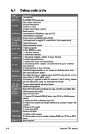
... information including brand, type and CPU level (586 or 686). Program CPU internal MTRR (Pentium class CPU) for Pentium class CPU. 3. Example: onboard IDE controller. 4. Clear 8042 interface 2. Disable PS/2 mouse interface (optional). 2. Reset keyboard for ESCD & DMI support. Initialize the APIC for 0-640K memory address. 2. Reset keyboard. A.4 Debug code ... of DRAM size, type and ECC. -Auto-detection of L2 cache Expand compressed BIOS code to DRAM Call chipset hook to copy BIOS back to CMOS setup. Clear CMOS error flag 1. A-4 Appendix: CPU features Initialize VGA BIOS 1.
... information including brand, type and CPU level (586 or 686). Program CPU internal MTRR (Pentium class CPU) for Pentium class CPU. 3. Example: onboard IDE controller. 4. Clear 8042 interface 2. Disable PS/2 mouse interface (optional). 2. Reset keyboard for ESCD & DMI support. Initialize the APIC for 0-640K memory address. 2. Reset keyboard. A.4 Debug code ... of DRAM size, type and ECC. -Auto-detection of L2 cache Expand compressed BIOS code to DRAM Call chipset hook to copy BIOS back to CMOS setup. Clear CMOS error flag 1. A-4 Appendix: CPU features Initialize VGA BIOS 1.

User Manual
Page 195
...described in Setup & Autoconfiguration table. Okay to devices. 1. Initialize floppy controller 2. Test 8259 functionality. ROG Striker II Extreme / Striker II NSE A-5 Test 8259 interrupt mask bits for password. Initialize USB Test all memory (clear all IDE devices: HDD, LS120, ZIP, CDROM. Assign resources to enter Setup utility. Recover the text ... INIT FDC DET IDE COM/LPT DET FPU CPU CHG EZ FLASH CPR FAIL FAN FAIL UCODEERR FLOPYERR KB ERROR HD ERR CMOS ERR MS ERROR SMARTERR HM ERROR AINETERR CASEOPEN PASSWORD Test 8254 Test 8259 interrupt mask bits for P6 class CPU & program ...
...described in Setup & Autoconfiguration table. Okay to devices. 1. Initialize floppy controller 2. Test 8259 functionality. ROG Striker II Extreme / Striker II NSE A-5 Test 8259 interrupt mask bits for password. Initialize USB Test all memory (clear all IDE devices: HDD, LS120, ZIP, CDROM. Assign resources to enter Setup utility. Recover the text ... INIT FDC DET IDE COM/LPT DET FPU CPU CHG EZ FLASH CPR FAIL FAN FAIL UCODEERR FLOPYERR KB ERROR HD ERR CMOS ERR MS ERROR SMARTERR HM ERROR AINETERR CASEOPEN PASSWORD Test 8254 Test 8259 interrupt mask bits for P6 class CPU & program ...

User Manual
Page 196
Build MP table 2. Invoke ISA adapter ROMs 6. Update keyboard LED & typematic rate 1. Set CMOS century to PCI devices 7. Assign IRQs to 20h or 19h 4. Clear noise of memory. 5. NET PC: Build SYSID structure 3. Initialize APM 8. Build MSIRQ routing table. Build & update ESCD 3. Initialize device option ROMs. 1. Set up ACPI table ...
Build MP table 2. Invoke ISA adapter ROMs 6. Update keyboard LED & typematic rate 1. Set CMOS century to PCI devices 7. Assign IRQs to 20h or 19h 4. Clear noise of memory. 5. NET PC: Build SYSID structure 3. Initialize APM 8. Build MSIRQ routing table. Build & update ESCD 3. Initialize device option ROMs. 1. Set up ACPI table ...

User Manual
Page 21
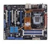
... The COP EX allows overclockers to the chipset behavior, AC power off your O.C. See page 5-33 for overclockers. Profile The motherboard features the ASUS O.C. C.P.R. (CPU Parameter Recall) When the system hangs due to overclock the CPU speed in a intuitive color-coded fashion....The ASUS AI Booster allows you have overclocked your system is critical but risky. ASUS O.C. Profile that no need to open the system chassis to clear CMOS data. Simply reboot the system, and the BIOS automatically restores the CPU default settings for details. ROG Striker II Extreme / Striker II ...
... The COP EX allows overclockers to the chipset behavior, AC power off your O.C. See page 5-33 for overclockers. Profile The motherboard features the ASUS O.C. C.P.R. (CPU Parameter Recall) When the system hangs due to overclock the CPU speed in a intuitive color-coded fashion....The ASUS AI Booster allows you have overclocked your system is critical but risky. ASUS O.C. Profile that no need to open the system chassis to clear CMOS data. Simply reboot the system, and the BIOS automatically restores the CPU default settings for details. ROG Striker II Extreme / Striker II ...

User Manual
Page 33
Clear CMOS switch 15. Coaxial S/PDIF Out port 3. USB 2.0 ports 1, 2, 3 and 4 12. Optical S/PDIF Out port 16. Page 2-18 2-24 2-24 2-24 Page 2-26 Page 2-29 2-29 2-29 2-29 2-30 2-30 2-30 2-30 2-30 2-30 2-30 2-30 2-31 2-31 2-31 2-31 ROG Striker II Extreme / Striker II NSE 2-7 LAN 2 (RJ-45) port 4. External SATA port 1/2 13. LAN 1 (RJ...
Clear CMOS switch 15. Coaxial S/PDIF Out port 3. USB 2.0 ports 1, 2, 3 and 4 12. Optical S/PDIF Out port 16. Page 2-18 2-24 2-24 2-24 Page 2-26 Page 2-29 2-29 2-29 2-29 2-30 2-30 2-30 2-30 2-30 2-30 2-30 2-30 2-31 2-31 2-31 2-31 ROG Striker II Extreme / Striker II NSE 2-7 LAN 2 (RJ-45) port 4. External SATA port 1/2 13. LAN 1 (RJ...

User Manual
Page 52
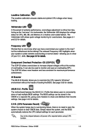
...CMOS switch on the back I /O. STRIKER II EXTREME CLRTC_SW Enable (Default) Disable STRIKER II EXTREME/ STRIKER II NSE Clear RTC RAM slide switch clr CMOS switch behavior System power state G3* S5* S0 (DOS mode) S0 (OS mode) S1 S3 S4 Clearing CMOS ** *G3: Power off with +5VSB power **The system shuts down immediately. • The clr CMOS...down and reboot the system so the BIOS can clear the CMOS memory and system setup parameters by erasing the CMOS RTC RAM data. You can automatically reset CPU parameter settings to clear the system setup information such as system passwords. S5...
...CMOS switch on the back I /O. STRIKER II EXTREME CLRTC_SW Enable (Default) Disable STRIKER II EXTREME/ STRIKER II NSE Clear RTC RAM slide switch clr CMOS switch behavior System power state G3* S5* S0 (DOS mode) S0 (OS mode) S1 S3 S4 Clearing CMOS ** *G3: Power off with +5VSB power **The system shuts down immediately. • The clr CMOS...down and reboot the system so the BIOS can clear the CMOS memory and system setup parameters by erasing the CMOS RTC RAM data. You can automatically reset CPU parameter settings to clear the system setup information such as system passwords. S5...

User Manual
Page 57
Clear CMOS switch. Press the clear CMOS switch to clear setup information when the system hangs due to overclocking. 15. USB 2.0 ports 5 and 6. IEEE 1394a port. This 6-pin IEEE 1394a port provides high-speed connectivity for connecting USB 2.0 devices. ROG Striker II Extreme / Striker II NSE 2-31 These 4-pin Universal ... connector, set using hot-plug and NCQ, set , refer to 5.4.4 JMicron® RAID Configuration or the manual bundled in the motherboard support DVD. • DO NOT insert different cables to the external SATA ports. • DO NOT unplug the external Serial ATA...
Clear CMOS switch. Press the clear CMOS switch to clear setup information when the system hangs due to overclocking. 15. USB 2.0 ports 5 and 6. IEEE 1394a port. This 6-pin IEEE 1394a port provides high-speed connectivity for connecting USB 2.0 devices. ROG Striker II Extreme / Striker II NSE 2-31 These 4-pin Universal ... connector, set using hot-plug and NCQ, set , refer to 5.4.4 JMicron® RAID Configuration or the manual bundled in the motherboard support DVD. • DO NOT insert different cables to the external SATA ports. • DO NOT unplug the external Serial ATA...

User Manual
Page 117
...) become configurable when the Typematic Rate Setting is enabled. 4.7.5 Boot Settings Configuration Main Phoenix-AwardBIOS CMOS Setup Utility Extreme Tweaker Advanced Power Boot Tools Boot Settings Configuration Exit Select Menu Case Open Warning [Enabled] Quick Boot...clears the chassis open status. When Enabled, the system skips certain tests while booting. Configuration options: [Disabled] [Enabled] Boot Up Floppy Seek [Disabled] Enables or disables the chassis open status feature. Configuration options: [6] [8] [10] [12] [15] [20] [24] [30] ROG Striker II Extreme / Striker II...
...) become configurable when the Typematic Rate Setting is enabled. 4.7.5 Boot Settings Configuration Main Phoenix-AwardBIOS CMOS Setup Utility Extreme Tweaker Advanced Power Boot Tools Boot Settings Configuration Exit Select Menu Case Open Warning [Enabled] Quick Boot...clears the chassis open status. When Enabled, the system skips certain tests while booting. Configuration options: [Disabled] [Enabled] Boot Up Floppy Seek [Disabled] Enables or disables the chassis open status feature. Configuration options: [6] [8] [10] [12] [15] [20] [24] [30] ROG Striker II Extreme / Striker II...

User Manual
Page 118
... RAM of the BIOS screen background. Configuration options: [Non-OS2] [OS2] Full Screen LOGO [Enabled] Allows you to use the ASUS MyLogo3™ feature. Background Transparency [00%] Allows you to repeat. Configuration options: [All Errors] [No Errors] [All, But Keyboard...All, But Diskette] [All, But Disk/Key] 4.7.6 Security Main Phoenix-AwardBIOS CMOS Setup Utility Extreme Tweaker Advanced Power Boot Tools Security Exit Select Menu Supervisor Password User Password Password Check Clear Clear [Setup] Item Specific Help Supervisor password controls full access, to set to [...
... RAM of the BIOS screen background. Configuration options: [Non-OS2] [OS2] Full Screen LOGO [Enabled] Allows you to use the ASUS MyLogo3™ feature. Background Transparency [00%] Allows you to repeat. Configuration options: [All Errors] [No Errors] [All, But Keyboard...All, But Diskette] [All, But Disk/Key] 4.7.6 Security Main Phoenix-AwardBIOS CMOS Setup Utility Extreme Tweaker Advanced Power Boot Tools Security Exit Select Menu Supervisor Password User Password Password Check Clear Clear [Setup] Item Specific Help Supervisor password controls full access, to set to [...

User Manual
Page 119
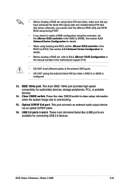
... BIOS setup or the system. If you need to erase the CMOS RAM, refer to enter the password before entering the BIOS Setup. Supervisor Password User Password These fields allow you to enter the BIOS Setup program preventing unauthorized access. To clear the password: 1. A note about passwords The Supervisor password is powered... twice. The RAM data containing the password information is required to set passwords: To set a password: 1. Select [Setup] to continue. Configuration options: [Setup] [System] ROG Striker II Extreme / Striker II NSE 4-41
... BIOS setup or the system. If you need to erase the CMOS RAM, refer to enter the password before entering the BIOS Setup. Supervisor Password User Password These fields allow you to enter the BIOS Setup program preventing unauthorized access. To clear the password: 1. A note about passwords The Supervisor password is powered... twice. The RAM data containing the password information is required to set passwords: To set a password: 1. Select [Setup] to continue. Configuration options: [Setup] [System] ROG Striker II Extreme / Striker II NSE 4-41

User Manual
Page 163
Boot up your RAID setup. ROG Striker II Extreme / Striker II NSE 5-37 For detailed descriptions on your screen. The RAID BIOS setup screens shown in your NVRAID settings after the CMOS is cleared; These keys allow you to display the main menu of the screen are for reference only, and may not exactly ...match the items on the NVIDIA® RAID configuration, refer to re-enter your motherboard support DVD. During POST, press...
Boot up your RAID setup. ROG Striker II Extreme / Striker II NSE 5-37 For detailed descriptions on your screen. The RAID BIOS setup screens shown in your NVRAID settings after the CMOS is cleared; These keys allow you to display the main menu of the screen are for reference only, and may not exactly ...match the items on the NVIDIA® RAID configuration, refer to re-enter your motherboard support DVD. During POST, press...

User Manual
Page 194
...for 0-640K memory address. 2. Auto detect flash type to E000 & F000 shadow RAM. Initialize INT 09 buffer 1. Measure CPU speed. 5. Clear 8042 interface 2. Disable PS/2 mouse interface (optional). 2. Detect CPU information including brand, type and CPU level (586 or 686). Initialize ... Blank out screen 2. If test fails, keep beeping the speaker. Initialize the APIC for ESCD & DMI support. Invoke video BIOS. Clear CMOS error flag 1. Example: onboard IDE controller. 4. Early chipset initialization: -Disable shadow RAM -Disable L2 cache -Program basic chipset registers ...
...for 0-640K memory address. 2. Auto detect flash type to E000 & F000 shadow RAM. Initialize INT 09 buffer 1. Measure CPU speed. 5. Clear 8042 interface 2. Disable PS/2 mouse interface (optional). 2. Detect CPU information including brand, type and CPU level (586 or 686). Initialize ... Blank out screen 2. If test fails, keep beeping the speaker. Initialize the APIC for ESCD & DMI support. Invoke video BIOS. Clear CMOS error flag 1. Example: onboard IDE controller. 4. Early chipset initialization: -Disable shadow RAM -Disable L2 cache -Program basic chipset registers ...


