English User Manual
Page 13
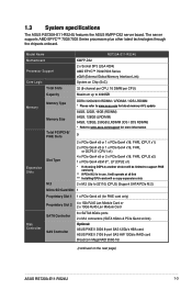
Model Name RS720A-E11-RS24U Motherboard Processor Support Core Logic KMPP-D32 2 x Socket SP3 (...Slots Slot Type Expansion Slots M.2 DDR4 3200/2933 RDIMM / LRDIMM / 3DS LRDIMM * Please refer to www.asus.com for latest memory AVL update 64GB, 32GB, 16GB (RDIMM) 64GB, 128GB (LRDIMM) 64GB, 128GB, 256GB (LRDIMM... x4 link) Optional: ASUS PIKE II 3008 8-port SAS 12Gb/s HBA card ASUS PIKE II 3108 8-port SAS HW 12Gb/s RAID card Broadcom MegaRAID 9560-16i (continued on the next page) ASUS RS720A-E11-RS24U 1-3 1.3 System specifications The ASUS RS720A-E11-RS24U features the ASUS KMPP-D32 server board...
Model Name RS720A-E11-RS24U Motherboard Processor Support Core Logic KMPP-D32 2 x Socket SP3 (...Slots Slot Type Expansion Slots M.2 DDR4 3200/2933 RDIMM / LRDIMM / 3DS LRDIMM * Please refer to www.asus.com for latest memory AVL update 64GB, 32GB, 16GB (RDIMM) 64GB, 128GB (LRDIMM) 64GB, 128GB, 256GB (LRDIMM... x4 link) Optional: ASUS PIKE II 3008 8-port SAS 12Gb/s HBA card ASUS PIKE II 3108 8-port SAS HW 12Gb/s RAID card Broadcom MegaRAID 9560-16i (continued on the next page) ASUS RS720A-E11-RS24U 1-3 1.3 System specifications The ASUS RS720A-E11-RS24U features the ASUS KMPP-D32 server board...

English User Manual
Page 15
ASUS RS720A-E11-RS24U 1-5 Model Name Security Options OS Support RS720A-E11-RS24U TPM-SPI PFR Windows® Server 2019 RedHat® Enterprise Linux SuSE® Linux Enterprise Server CentOS Ubuntu VMware * Please find the latest OS support from http://www.asus.com Management Solution Software Out of Band ...storage device not included) Gross Weight Kg (CPU, DRAM & storage device not included, packing included) Power Supply (different configuration by region) Environment ASUS Control Center On-Board ASMB10-iKVM for KVM-over-IP BSMI, CE, C-Tick, FCC(Class A) 840 mm x 449 mm x 88.1 mm...
ASUS RS720A-E11-RS24U 1-5 Model Name Security Options OS Support RS720A-E11-RS24U TPM-SPI PFR Windows® Server 2019 RedHat® Enterprise Linux SuSE® Linux Enterprise Server CentOS Ubuntu VMware * Please find the latest OS support from http://www.asus.com Management Solution Software Out of Band ...storage device not included) Gross Weight Kg (CPU, DRAM & storage device not included, packing included) Power Supply (different configuration by region) Environment ASUS Control Center On-Board ASMB10-iKVM for KVM-over-IP BSMI, CE, C-Tick, FCC(Class A) 840 mm x 449 mm x 88.1 mm...

English User Manual
Page 17
SATA/SAS back panel 6. WARNING HAZARDOUS MOVING PARTS KEEP FINGERS AND OTHER BODY PARTS AWAY ASUS RS720A-E11-RS24U 1-7 System fans 5. Redundant Power supply (hidden) 3. Please remove the protection film before shipping. Front panel (hidden) 7. 24 x 2.5" storage device... trays The barebone server does not include a floppy disk drive. Connect a USB floppy disk drive to use a floppy disk. ASUS KMPP-D32 Server Board 4. Riser card bracket 2. 1.6 Internal features The barebone server includes the basic components as shown. 24 NVMe non-GPU model 1. A ...
SATA/SAS back panel 6. WARNING HAZARDOUS MOVING PARTS KEEP FINGERS AND OTHER BODY PARTS AWAY ASUS RS720A-E11-RS24U 1-7 System fans 5. Redundant Power supply (hidden) 3. Please remove the protection film before shipping. Front panel (hidden) 7. 24 x 2.5" storage device... trays The barebone server does not include a floppy disk drive. Connect a USB floppy disk drive to use a floppy disk. ASUS KMPP-D32 Server Board 4. Riser card bracket 2. 1.6 Internal features The barebone server includes the basic components as shown. 24 NVMe non-GPU model 1. A ...
English User Manual
Page 19
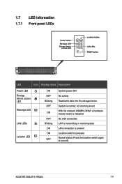
... System power ON No activity Read/write data into the storage device System is pressed Normal status (Press the location switch again to turn off) ASUS RS720A-E11-RS24U 1-9 no incoming event With the onboard ASMB10-iKVM: a hardware monitor event is indicated No LAN connection LAN is transmitting or receiving data LAN connection is...
... System power ON No activity Read/write data into the storage device System is pressed Normal status (Press the location switch again to turn off) ASUS RS720A-E11-RS24U 1-9 no incoming event With the onboard ASMB10-iKVM: a hardware monitor event is indicated No LAN connection LAN is transmitting or receiving data LAN connection is...

English User Manual
Page 21
1.7.3 LAN (RJ-45) LEDs Intel® I350-AM4 1G LAN port LEDs ACT/LINK LED SPEED LED ACT/LINK LED Status Description OFF No link GREEN Linked BLINKING Data activity SPEED LED Status Description OFF 10 Mbps connection ORANGE 100 Mbps connection GREEN 1 Gbps connection Intel® X710-AT2 Gigabit 10G LAN port LEDs ACT/LINK LED SPEED LED ACT/LINK LED Status Description OFF No link GREEN Linked BLINKING Data activity Status OFF ORANGE GREEN SPEED LED Description 10 Mbps / 100 Mbps connection 1 Gbps connection 10 Gbps connection ASUS RS720A-E11-RS24U 1-11
1.7.3 LAN (RJ-45) LEDs Intel® I350-AM4 1G LAN port LEDs ACT/LINK LED SPEED LED ACT/LINK LED Status Description OFF No link GREEN Linked BLINKING Data activity SPEED LED Status Description OFF 10 Mbps connection ORANGE 100 Mbps connection GREEN 1 Gbps connection Intel® X710-AT2 Gigabit 10G LAN port LEDs ACT/LINK LED SPEED LED ACT/LINK LED Status Description OFF No link GREEN Linked BLINKING Data activity Status OFF ORANGE GREEN SPEED LED Description 10 Mbps / 100 Mbps connection 1 Gbps connection 10 Gbps connection ASUS RS720A-E11-RS24U 1-11

English User Manual
Page 23
... not consistent Uncompressed image size doesn't match value in compressed header Compressed option used in case where not supported Fuse info on the next page) ASUS RS720A-E11-RS24U 1-13 internal status Booted from boot source not recognized by PSP PSP directory entry not found PSP failed to set the write enable latch PSP...
... not consistent Uncompressed image size doesn't match value in compressed header Compressed option used in case where not supported Fuse info on the next page) ASUS RS720A-E11-RS24U 1-13 internal status Booted from boot source not recognized by PSP PSP directory entry not found PSP failed to set the write enable latch PSP...

English User Manual
Page 25
... initialization failed Knoll failed to idle correctly after being reset Bad status returned by I2CKnollCheck NACK to general call (no device on the next page) ASUS RS720A-E11-RS24U 1-15
... initialization failed Knoll failed to idle correctly after being reset Bad status returned by I2CKnollCheck NACK to general call (no device on the next page) ASUS RS720A-E11-RS24U 1-15

English User Manual
Page 27
Action PSP Boot PHASE PSP Boot Loader phase (Status Post Codes) POST CODE 0xC0 0xC1 0xC2 0xC3 0xC4 0xC5 0xC6 0xC7 0xC8 0xC9 0xCA 0xCB 0xCC 0xCD 0xCE 0xCF 0xD0 0xD1 0xD2 0xD3 0xD4 0xD5 0xD6 0xD7 0xD8 0xD9 TYPE Progress Progress Progress Progress Progress Progress Progress Progress Progress Progress Progress Progress Progress Progress Progress Progress Progress Progress Progress Progress Progress Progress Progress Progress Progress Progress DESCRIPTION Successfully entered WarmBootResume() Successfully copied SecureOS image to SRAM Successfully copied trustlets to PSP Secure Memory About to ...
Action PSP Boot PHASE PSP Boot Loader phase (Status Post Codes) POST CODE 0xC0 0xC1 0xC2 0xC3 0xC4 0xC5 0xC6 0xC7 0xC8 0xC9 0xCA 0xCB 0xCC 0xCD 0xCE 0xCF 0xD0 0xD1 0xD2 0xD3 0xD4 0xD5 0xD6 0xD7 0xD8 0xD9 TYPE Progress Progress Progress Progress Progress Progress Progress Progress Progress Progress Progress Progress Progress Progress Progress Progress Progress Progress Progress Progress Progress Progress Progress Progress Progress Progress DESCRIPTION Successfully entered WarmBootResume() Successfully copied SecureOS image to SRAM Successfully copied trustlets to PSP Secure Memory About to ...

English User Manual
Page 31
... supported Attempt to unmap permanently mapped TLB to PSP secure region Unable to map an SMN address to AXI space (continued on the next page) ASUS RS720A-E11-RS24U 1-21 Action PSP Boot PHASE POST CODE 0x20 0x21 0x22 0x23 0x24 0x25 0x26 0x27 0x28 0x29 0x2A 0x2B PSP Boot Loader phase (Error Post...
... supported Attempt to unmap permanently mapped TLB to PSP secure region Unable to map an SMN address to AXI space (continued on the next page) ASUS RS720A-E11-RS24U 1-21 Action PSP Boot PHASE POST CODE 0x20 0x21 0x22 0x23 0x24 0x25 0x26 0x27 0x28 0x29 0x2A 0x2B PSP Boot Loader phase (Error Post...

English User Manual
Page 33
... whilst attempting to SMN map a fuse register Fuse burn sequence/operation failed due to DRAM Error validating BIOS image signature (continued on the next page) ASUS RS720A-E11-RS24U 1-23 Reset image not found Generic error indicating the CCP HAL initialization failed failure to copy NVRAM to DRAM. BIOS level 2 directory not match expected...
... whilst attempting to SMN map a fuse register Fuse burn sequence/operation failed due to DRAM Error validating BIOS image signature (continued on the next page) ASUS RS720A-E11-RS24U 1-23 Reset image not found Generic error indicating the CCP HAL initialization failed failure to copy NVRAM to DRAM. BIOS level 2 directory not match expected...

English User Manual
Page 35
... Initialization SB DXE Initialization SB DXE SMM Initialization SB DEVICES Initialization ACPI Module Initialization CSM Initialization CPU PM Structure Initialization (continued on the next page) ASUS RS720A-E11-RS24U 1-25
... Initialization SB DXE Initialization SB DXE SMM Initialization SB DEVICES Initialization ACPI Module Initialization CSM Initialization CPU PM Structure Initialization (continued on the next page) ASUS RS720A-E11-RS24U 1-25

English User Manual
Page 39
Remove the two (2) screws on both sides of the mid cover with a Phillips screwdriver. 2. ASUS RS720A-E11-RS24U 2-3 Removing the mid cover 1. Push the buttons on both sides to disengage it from the chassis. 4. Slide the mid cover towards the rear panel to release the mid cover from the chassis. Lift the mid cover from the chassis. 3.
Remove the two (2) screws on both sides of the mid cover with a Phillips screwdriver. 2. ASUS RS720A-E11-RS24U 2-3 Removing the mid cover 1. Push the buttons on both sides to disengage it from the chassis. 4. Slide the mid cover towards the rear panel to release the mid cover from the chassis. Lift the mid cover from the chassis. 3.

English User Manual
Page 41
ASUS RS720A-E11-RS24U 2-5 Remove the four (4) screws from the chassis. 2. Gently lift the air ducts vertically out of the chassis. 12 NVMe GPU model To remove the air ducts: 1.
ASUS RS720A-E11-RS24U 2-5 Remove the four (4) screws from the chassis. 2. Gently lift the air ducts vertically out of the chassis. 12 NVMe GPU model To remove the air ducts: 1.
English User Manual
Page 43
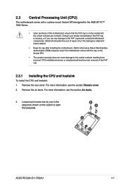
...not bent. Remove the rear cover. For more information, see the section Air ducts. 3. For more information, see the section Chassis cover. 2. ASUS RS720A-E11-RS24U 2-7 2.3 Central Processing Unit (CPU) The motherboard comes with the cap on the Socket SP3. • The product warranty does not cover damage to...: 1. Contact your retailer immediately if the PnP cap is shipment/ transit-related. • Keep the cap after installing the motherboard. ASUS will shoulder the cost of repair only if the damage is missing, or if you see any damage to the PnP cap/socket contacts...
...not bent. Remove the rear cover. For more information, see the section Air ducts. 3. For more information, see the section Chassis cover. 2. ASUS RS720A-E11-RS24U 2-7 2.3 Central Processing Unit (CPU) The motherboard comes with the cap on the Socket SP3. • The product warranty does not cover damage to...: 1. Contact your retailer immediately if the PnP cap is shipment/ transit-related. • Keep the cap after installing the motherboard. ASUS will shoulder the cost of repair only if the damage is missing, or if you see any damage to the PnP cap/socket contacts...

English User Manual
Page 45
... screw one by one in the illustration to completely secure the load plate. The heatsink screws are T20 models. A torque value of the CPU socket. ASUS RS720A-E11-RS24U 2-9 When the four screws are attached, tighten them one by one in the sequence shown in the sequence shown on top of 16.1±1.2 kgf...
... screw one by one in the illustration to completely secure the load plate. The heatsink screws are T20 models. A torque value of the CPU socket. ASUS RS720A-E11-RS24U 2-9 When the four screws are attached, tighten them one by one in the sequence shown in the sequence shown on top of 16.1±1.2 kgf...
English User Manual
Page 47
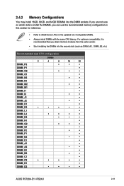
If you are not sure on which slots to ASUS Server AVL for the updated list of compatible DIMMs. • Always install DIMMs with the same CAS latency. For optimum compatibility, it is recommended that ...; • • • • • • • • • • • • • • • • • • • • • • • • • ASUS RS720A-E11-RS24U 2-11
If you are not sure on which slots to ASUS Server AVL for the updated list of compatible DIMMs. • Always install DIMMs with the same CAS latency. For optimum compatibility, it is recommended that ...; • • • • • • • • • • • • • • • • • • • • • • • • • ASUS RS720A-E11-RS24U 2-11
English User Manual
Page 49
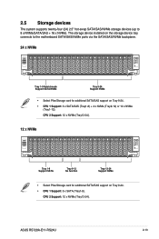
... Support SATA/NVMe Tray 9-24 Support NVMe • Select Pike/Storage card for additional SATA/SAS support on Tray 9-24. • CPU 1 Support: 8 x SATA (Tray1-8). ASUS RS720A-E11-RS24U 2-13 The storage device installed on Tray 9-24. • CPU 1 Support: 8 x SATA/SAS (Tray1-8) + 4 x NVMe (Tray9-12) or 12 x NVMe (Tray1-12). CPU 2 Support: 12...
... Support SATA/NVMe Tray 9-24 Support NVMe • Select Pike/Storage card for additional SATA/SAS support on Tray 9-24. • CPU 1 Support: 8 x SATA (Tray1-8). ASUS RS720A-E11-RS24U 2-13 The storage device installed on Tray 9-24. • CPU 1 Support: 8 x SATA/SAS (Tray1-8) + 4 x NVMe (Tray9-12) or 12 x NVMe (Tray1-12). CPU 2 Support: 12...
English User Manual
Page 51
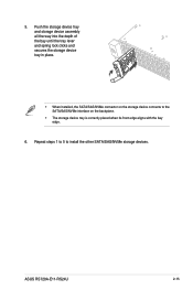
5. Repeat steps 1 to 5 to the SATA/SAS/NVMe interface on the storage device connects to install the other SATA/SAS/NVMe storage devices. Push the storage device tray and storage device assembly all the way into the depth of the bay until the tray lever and spring lock clicks and secures the storage device tray in place. • When installed, the SATA/SAS/NVMe connector on the backplane. • The storage device tray is correctly placed when its front edge aligns with the bay edge. 6. ASUS RS720A-E11-RS24U 2-15
5. Repeat steps 1 to 5 to the SATA/SAS/NVMe interface on the storage device connects to install the other SATA/SAS/NVMe storage devices. Push the storage device tray and storage device assembly all the way into the depth of the bay until the tray lever and spring lock clicks and secures the storage device tray in place. • When installed, the SATA/SAS/NVMe connector on the backplane. • The storage device tray is correctly placed when its front edge aligns with the bay edge. 6. ASUS RS720A-E11-RS24U 2-15
English User Manual
Page 53
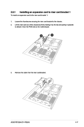
2.6.1 Installing an expansion card to riser card bracket 1 To install an expansion card to detach it from the riser card bracket. Lift the riser card out of the chassis by firmly holding it by the tab and pulling it upwards to the riser card bracket 1: 1. ASUS RS720A-E11-RS24U 2-17 Loosen the thumbscrew securing the riser card bracket to the chassis. 2. Remove the cable from the PCIE slot on the motherboard. 3.
2.6.1 Installing an expansion card to riser card bracket 1 To install an expansion card to detach it from the riser card bracket. Lift the riser card out of the chassis by firmly holding it by the tab and pulling it upwards to the riser card bracket 1: 1. ASUS RS720A-E11-RS24U 2-17 Loosen the thumbscrew securing the riser card bracket to the chassis. 2. Remove the cable from the PCIE slot on the motherboard. 3.
English User Manual
Page 55
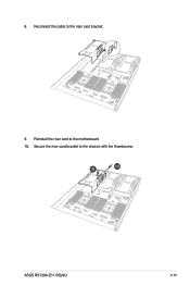
Secure the riser card bracket to the riser card bracket. 9. Reconnect the cable to the chassis with the thumbscrew. ASUS RS720A-E11-RS24U 2-19 Reinstall the riser card to the motherboard. 10. 8.
Secure the riser card bracket to the riser card bracket. 9. Reconnect the cable to the chassis with the thumbscrew. ASUS RS720A-E11-RS24U 2-19 Reinstall the riser card to the motherboard. 10. 8.


