
User Manual
Page 11
ASUS RS520-X5/PS8 1- It includes sections on front panel and rear panel specifications. Product introduction Chapter 1 This chapter describes the general features of the chassis kit.
ASUS RS520-X5/PS8 1- It includes sections on front panel and rear panel specifications. Product introduction Chapter 1 This chapter describes the general features of the chassis kit.

User Manual
Page 13
1.3 System specifications The ASUS RS520-X5/PS8 is a server featuring the ASUS DSBV-DX/SAS server board. Intel® Xeon® E5200 series FSB 1333 / 1066 / 667 MHz Intel® 5000V MCH (Blackford-VS) Intel® 6321ESB (... 0, RAID 1, and RAID 1E configuration Zero-Channel RAID (colored green) 8 x Hot-swap 3.5" SAS/SATA HDD Bays (continued on the next page) ASUS RS520-X5/PS8 1-3 Model Name Processor / System Bus Core Logic ASUS Features Memory Smart Fan ASWM 2.0 Total Slots Capacity Memory Type Memory Size Total PCI/PCI-X/ PCI-E Slots Expansion Slots Slot Type Storage...
1.3 System specifications The ASUS RS520-X5/PS8 is a server featuring the ASUS DSBV-DX/SAS server board. Intel® Xeon® E5200 series FSB 1333 / 1066 / 667 MHz Intel® 5000V MCH (Blackford-VS) Intel® 6321ESB (... 0, RAID 1, and RAID 1E configuration Zero-Channel RAID (colored green) 8 x Hot-swap 3.5" SAS/SATA HDD Bays (continued on the next page) ASUS RS520-X5/PS8 1-3 Model Name Processor / System Bus Core Logic ASUS Features Memory Smart Fan ASWM 2.0 Total Slots Capacity Memory Type Memory Size Total PCI/PCI-X/ PCI-E Slots Expansion Slots Slot Type Storage...

User Manual
Page 15
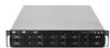
... LAN port2 LAN port1 VGA port Serial port USB ports PS/2 keyboard port PS/2 mouse port Power supply switch Power cord connector Power supply fan ASUS RS520-X5/PS8 1-5
... LAN port2 LAN port1 VGA port Serial port USB ports PS/2 keyboard port PS/2 mouse port Power supply switch Power cord connector Power supply fan ASUS RS520-X5/PS8 1-5
User Manual
Page 17
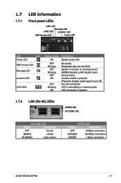
... Status Description OFF No link GREEN Linked BLINKING Data activity SPEED LED Status Description OFF 10 Mbps connection ORANGE 100 Mbps connection GREEN 1 Gbps connection ASUS RS520-X5/PS8 1-7 no incoming event ASWM indicates a HW monitor event Normal status Location switch is pressed (Press the location switch again to turn off) No LAN connection...
... Status Description OFF No link GREEN Linked BLINKING Data activity SPEED LED Status Description OFF 10 Mbps connection ORANGE 100 Mbps connection GREEN 1 Gbps connection ASUS RS520-X5/PS8 1-7 no incoming event ASWM indicates a HW monitor event Normal status Location switch is pressed (Press the location switch again to turn off) No LAN connection...

User Manual
Page 19
Hardware setup Chapter 2 This chapter lists the hardware setup procedures that you have to perform when installing or removing system components. ASUS RS520-X5/PS8 2-
Hardware setup Chapter 2 This chapter lists the hardware setup procedures that you have to perform when installing or removing system components. ASUS RS520-X5/PS8 2-

User Manual
Page 21
... you and the load lever is shipment/transit-related. • Keep the cap after installing the motherboard. ASUS will process Return Merchandise Authorization (RMA) requests only if the motherboard comes with installation instructions for the Intel®...socket. • The product warranty does not cover damage to the PnP cap/socket contacts/motherboard components. ASUS will shoulder the cost of the motherboard, ensure that the socket box is facing towards you see any...motherboard comes with a surface mount LGA771 socket designed for the CPU and heatsink. ASUS RS520-X5/PS8 2-3
... you and the load lever is shipment/transit-related. • Keep the cap after installing the motherboard. ASUS will process Return Merchandise Authorization (RMA) requests only if the motherboard comes with installation instructions for the Intel®...socket. • The product warranty does not cover damage to the PnP cap/socket contacts/motherboard components. ASUS will shoulder the cost of the motherboard, ensure that the socket box is facing towards you see any...motherboard comes with a surface mount LGA771 socket designed for the CPU and heatsink. ASUS RS520-X5/PS8 2-3

User Manual
Page 23
A 6. The CPU fits in only one correct orientation. B ASUS RS520-X5/PS8 2-5 DO NOT force the CPU into the retention tab. Close the load plate (A), then push the load lever (B) until it snaps into the socket to prevent bending the connectors on the socket and damaging the CPU!
A 6. The CPU fits in only one correct orientation. B ASUS RS520-X5/PS8 2-5 DO NOT force the CPU into the retention tab. Close the load plate (A), then push the load lever (B) until it snaps into the socket to prevent bending the connectors on the socket and damaging the CPU!

User Manual
Page 25
...System memory 2.3.1 Overview The motherboard comes with six fully-buffered DIMM (FB-DIMM) sockets to the Qualified Vendors List on an FB-DIMM socket. ASUS RS520-X5/PS8 2-7 Note that an FB-DIMM socket has an Advanced Memory Buffer (AMB) chip that you obtain memory modules from DDR2 DIMMs so you are... same vendor. The figure illustrates the location of 128 Mb chips x16 memory modules. • If you cannot install DDR2 DIMMs on the ASUS web site. • This motherboard does not support memory modules made up of the FB-DIMM sockets: 2.3.2 Memory configurations You may install 256...
...System memory 2.3.1 Overview The motherboard comes with six fully-buffered DIMM (FB-DIMM) sockets to the Qualified Vendors List on an FB-DIMM socket. ASUS RS520-X5/PS8 2-7 Note that an FB-DIMM socket has an Advanced Memory Buffer (AMB) chip that you obtain memory modules from DDR2 DIMMs so you are... same vendor. The figure illustrates the location of 128 Mb chips x16 memory modules. • If you cannot install DDR2 DIMMs on the ASUS web site. • This motherboard does not support memory modules made up of the FB-DIMM sockets: 2.3.2 Memory configurations You may install 256...

User Manual
Page 27
... 0 Channel 1 DIMM_00 (2048MB/2 Ranks) Rank 0 Rank 1 (1024 MB) (1024 MB) DIMM_10 (2048MB/2 Ranks) Rank 0 Rank 1 (1024 MB) (1024 MB) V V 1024 MB 1024 MB 2048 MB ASUS RS520-X5/PS8 2-9 To support sparing function, a DIMM channel should contain at least two ranks. • When sparing function is set aside to 5.4.2 Chipset Configuration and configure the...
... 0 Channel 1 DIMM_00 (2048MB/2 Ranks) Rank 0 Rank 1 (1024 MB) (1024 MB) DIMM_10 (2048MB/2 Ranks) Rank 0 Rank 1 (1024 MB) (1024 MB) V V 1024 MB 1024 MB 2048 MB ASUS RS520-X5/PS8 2-9 To support sparing function, a DIMM channel should contain at least two ranks. • When sparing function is set aside to 5.4.2 Chipset Configuration and configure the...

User Manual
Page 29
... it flips out with extra force. 1 2. Support the DIMM lightly with a notch so that the notch on the DIMM matches the break on the socket. 3. ASUS RS520-X5/PS8 2-11 Unlock a DIMM socket by pressing the retaining clips outward. 2. The DIMM might get damaged when it fits in place and the DIMM 1 is properly...
... it flips out with extra force. 1 2. Support the DIMM lightly with a notch so that the notch on the DIMM matches the break on the socket. 3. ASUS RS520-X5/PS8 2-11 Unlock a DIMM socket by pressing the retaining clips outward. 2. The DIMM might get damaged when it fits in place and the DIMM 1 is properly...

User Manual
Page 31
... wish to the SATAII/ SAS interface on the backplane. 6. Carefully insert the drive tray and push it clicks, and secures the drive tray in place. ASUS RS520-X5/PS8 2-13 Push the tray lever until it all the way to section 2.7 SATAII/SAS backplane cabling for information on the drive connects to install a second...
... wish to the SATAII/ SAS interface on the backplane. 6. Carefully insert the drive tray and push it clicks, and secures the drive tray in place. ASUS RS520-X5/PS8 2-13 Push the tray lever until it all the way to section 2.7 SATAII/SAS backplane cabling for information on the drive connects to install a second...
User Manual
Page 33
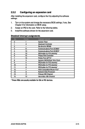
... PCI steering* PS/2 Compatible Mouse Port* Numeric Data Processor Primary IDE Channel Secondary IDE Channel * These IRQs are usually available for ISA or PCI devices. ASUS RS520-X5/PS8 2-15 Standard interrupt assignments IRQ Priority Standard Function 0 1 1 2 2 - 3 11 4 12 5 13 6 14 7 15 8 3 9 4 10 5 11 6 12 7 13 8 14 9 15 10 System Timer Keyboard Controller...
... PCI steering* PS/2 Compatible Mouse Port* Numeric Data Processor Primary IDE Channel Secondary IDE Channel * These IRQs are usually available for ISA or PCI devices. ASUS RS520-X5/PS8 2-15 Standard interrupt assignments IRQ Priority Standard Function 0 1 1 2 2 - 3 11 4 12 5 13 6 14 7 15 8 3 9 4 10 5 11 6 12 7 13 8 14 9 15 10 System Timer Keyboard Controller...

User Manual
Page 35
... SAS3 SAS4 SAS5 SAS6 SAS7 SAS8 Back side connector CON1 CON2 CON3 CON4 CON5 CON6 CON7 CON8 Back side The back side of the backplane. ASUS RS520-X5/PS8 2-17 Front side The front side of the SATAII/SAS backplane faces the front panel when installed. This side includes the power connectors and SATAII...
... SAS3 SAS4 SAS5 SAS6 SAS7 SAS8 Back side connector CON1 CON2 CON3 CON4 CON5 CON6 CON7 CON8 Back side The back side of the backplane. ASUS RS520-X5/PS8 2-17 Front side The front side of the SATAII/SAS backplane faces the front panel when installed. This side includes the power connectors and SATAII...

User Manual
Page 37
Push the slim optical drive all the way to the depth of the bay until it clicks in place. To uninstall the slim optical drive: 1. Press the latch leftward, and push the slim optical drive toward the front panel. Insert the slim optical drive into the drive bay. 3. Locate the optical drive eject latch at the rear side. 2. ASUS RS520-X5/PS8 2-19 Remove the dummy covor for the optical drive bay. 2. 2.8.2 Optical drive (optional) To install the slim optical drive: 1.
Push the slim optical drive all the way to the depth of the bay until it clicks in place. To uninstall the slim optical drive: 1. Press the latch leftward, and push the slim optical drive toward the front panel. Insert the slim optical drive into the drive bay. 3. Locate the optical drive eject latch at the rear side. 2. ASUS RS520-X5/PS8 2-19 Remove the dummy covor for the optical drive bay. 2. 2.8.2 Optical drive (optional) To install the slim optical drive: 1.

User Manual
Page 39
Installation options Chapter 3 This chapter describes how to install the optional components and devices into the barebone server. ASUS RS520-X5/PS8 2-
Installation options Chapter 3 This chapter describes how to install the optional components and devices into the barebone server. ASUS RS520-X5/PS8 2-

User Manual
Page 41
... rail toward the front panel until it locks in place. 2. Repeat steps 1 to 3 to attach the second server rail to the side of the chassis. ASUS RS520-X5/PS8 3-3 Secure the server rail to the other side of the chassis with two screws. 4. Attach the front end of the server rail to the side...
... rail toward the front panel until it locks in place. 2. Repeat steps 1 to 3 to attach the second server rail to the side of the chassis. ASUS RS520-X5/PS8 3-3 Secure the server rail to the other side of the chassis with two screws. 4. Attach the front end of the server rail to the side...

User Manual
Page 43
ASUS RS520-X5/PS8 3- 4-1 Motherboard info Chapter 4 This chapter includes the motherboard layout, and brief descriptions of the jumpers and internal connectors.
ASUS RS520-X5/PS8 3- 4-1 Motherboard info Chapter 4 This chapter includes the motherboard layout, and brief descriptions of the jumpers and internal connectors.

User Manual
Page 47
ASUS RS520-X5/PS8 4-5 Set to pins 1-2 to set the LAN bandwidth setting for more efficient IP load distribution. 3. 2. LAN bandwidth setting (3-pin LAN_BW1) This jumper allows you to enable or disable the onboard VGA controller. VGA controller setting (3-pin VGA_EN1) These jumpers allow you to activate the VGA feature.
ASUS RS520-X5/PS8 4-5 Set to pins 1-2 to set the LAN bandwidth setting for more efficient IP load distribution. 3. 2. LAN bandwidth setting (3-pin LAN_BW1) This jumper allows you to enable or disable the onboard VGA controller. VGA controller setting (3-pin VGA_EN1) These jumpers allow you to activate the VGA feature.

User Manual
Page 49
... setting (3-pin SAS_EN1) This jumper allows you to enable or disable the onboard LSI1068 SAS controller. Insert the floppy disk then turn on the system. ASUS RS520-X5/PS8 4-7 6. Prepare a floppy disk that contains the latest BIOS for your motherboard model. 2. Set the jumper to pins 1-2 to pins 2-3. 3. Force BIOS recovery setting (3-pin RECOVERY1...
... setting (3-pin SAS_EN1) This jumper allows you to enable or disable the onboard LSI1068 SAS controller. Insert the floppy disk then turn on the system. ASUS RS520-X5/PS8 4-7 6. Prepare a floppy disk that contains the latest BIOS for your motherboard model. 2. Set the jumper to pins 1-2 to pins 2-3. 3. Force BIOS recovery setting (3-pin RECOVERY1...

User Manual
Page 51
Hard disk activity LED connector (4-pin HDLED1) This connector is used to connect to a hard disk drive active LED connector on the SCSI or RAID card. 3. ASUS RS520-X5/PS8 4-9 Serial ATA connectors (7-pin SATA1, SATA2, SATA3, SATA4, SATA5, SATA6 ) These connectors are for the Serial ATA signal cables for Serial ATA hard disk drives. 4.
Hard disk activity LED connector (4-pin HDLED1) This connector is used to connect to a hard disk drive active LED connector on the SCSI or RAID card. 3. ASUS RS520-X5/PS8 4-9 Serial ATA connectors (7-pin SATA1, SATA2, SATA3, SATA4, SATA5, SATA6 ) These connectors are for the Serial ATA signal cables for Serial ATA hard disk drives. 4.


