
User Manual
Page 5
... Devices Configuration 5-24 5.4.6 ACPI Configuration 5-26 5.4.7 Power On Configuration 5-27 5.4.8 Hardware Monitor 5-28 5.5 Server menu 5-31 5.5.1 Console Redirection 5-31 5.5.2 DMI Event Logging 5-33 5.6 Security menu 5-34 5.7 Boot menu 5-36 5.7.1 Boot Device Priority 5-36 5.7.2 Boot Features 5-37 5.8 Exit menu 5-38 Chapter 6: RAID configuration 6.1 Setting up RAID 6-2 6.1.1 RAID definitions 6-2 6.1.2 Installing hard disk drives 6-3 6.1.3 Setting the RAID item in BIOS 6-3 6.1.4 RAID configuration utilities 6-3 6.2 Intel® Matrix Storage Manager Option ROM Utility...
... Devices Configuration 5-24 5.4.6 ACPI Configuration 5-26 5.4.7 Power On Configuration 5-27 5.4.8 Hardware Monitor 5-28 5.5 Server menu 5-31 5.5.1 Console Redirection 5-31 5.5.2 DMI Event Logging 5-33 5.6 Security menu 5-34 5.7 Boot menu 5-36 5.7.1 Boot Device Priority 5-36 5.7.2 Boot Features 5-37 5.8 Exit menu 5-38 Chapter 6: RAID configuration 6.1 Setting up RAID 6-2 6.1.1 RAID definitions 6-2 6.1.2 Installing hard disk drives 6-3 6.1.3 Setting the RAID item in BIOS 6-3 6.1.4 RAID configuration utilities 6-3 6.2 Intel® Matrix Storage Manager Option ROM Utility...
User Manual
Page 9
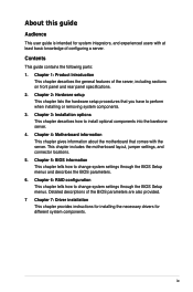
... hardware setup procedures that comes with at least basic knowledge of the BIOS parameters are also provided. 7 Chapter 7: Driver installation This chapter provides instructions for installing the necessary drivers for system integrators, and experienced users with the server. This chapter includes the motherboard layout, jumper settings, and connector locations. 5. Chapter 1: Product Introduction This chapter describes the general features of the server, including sections on front panel and rear panel specifications...
... hardware setup procedures that comes with at least basic knowledge of the BIOS parameters are also provided. 7 Chapter 7: Driver installation This chapter provides instructions for installing the necessary drivers for system integrators, and experienced users with the server. This chapter includes the motherboard layout, jumper settings, and connector locations. 5. Chapter 1: Product Introduction This chapter describes the general features of the server, including sections on front panel and rear panel specifications...

User Manual
Page 13
... x SATA II 300MB/s ports Intel® Matrix Storage (for Windows only) - Model Name Processor / System Bus Core Logic ASUS Features Memory Smart Fan ASWM 2.0 Total Slots Capacity Memory Type Memory Size Total PCI/PCI-X/ PCI-E Slots Expansion Slots Slot Type Storage HDD Bays SATA Controller SAS Controller I = Internal A or S will be hot-swappable RS520-X5/PS8 2 x Socket LGA771 Quad-Core: - The server supports Intel® LGA771 Xeon® 5400/5200 series processors with RAID 0, RAID 1, and RAID 1E configuration Zero-Channel RAID (colored green) 8 x Hot-swap 3.5" SAS/SATA HDD...
... x SATA II 300MB/s ports Intel® Matrix Storage (for Windows only) - Model Name Processor / System Bus Core Logic ASUS Features Memory Smart Fan ASWM 2.0 Total Slots Capacity Memory Type Memory Size Total PCI/PCI-X/ PCI-E Slots Expansion Slots Slot Type Storage HDD Bays SATA Controller SAS Controller I = Internal A or S will be hot-swappable RS520-X5/PS8 2 x Socket LGA771 Quad-Core: - The server supports Intel® LGA771 Xeon® 5400/5200 series processors with RAID 0, RAID 1, and RAID 1E configuration Zero-Channel RAID (colored green) 8 x Hot-swap 3.5" SAS/SATA HDD...
User Manual
Page 17
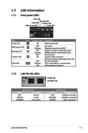
...Power LED LED Icon Power LED HDD Access LED Message LED Location LED LAN LEDs Display status Description ON System power ON OFF Blinking OFF Blinking OFF ON OFF Blinking ON No activity Read/write data into the HDD System is present 1.7.2 LAN (RJ-45) LEDs SPEED LED ACT/LINK LED ACT/LINK LED Status Description OFF No link GREEN Linked BLINKING Data activity SPEED LED Status Description OFF 10 Mbps connection ORANGE 100 Mbps connection GREEN 1 Gbps connection ASUS RS520-X5/PS8 1-7 no incoming event ASWM indicates a HW monitor event Normal status Location switch...
...Power LED LED Icon Power LED HDD Access LED Message LED Location LED LAN LEDs Display status Description ON System power ON OFF Blinking OFF Blinking OFF ON OFF Blinking ON No activity Read/write data into the HDD System is present 1.7.2 LAN (RJ-45) LEDs SPEED LED ACT/LINK LED ACT/LINK LED Status Description OFF No link GREEN Linked BLINKING Data activity SPEED LED Status Description OFF 10 Mbps connection ORANGE 100 Mbps connection GREEN 1 Gbps connection ASUS RS520-X5/PS8 1-7 no incoming event ASWM indicates a HW monitor event Normal status Location switch...
User Manual
Page 33
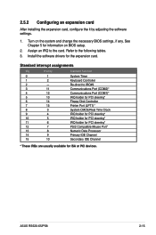
2.5.2 Configuring an expansion card After installing the expansion card, configure the it by adjusting the software settings. 1. See Chapter 5 for information on the system and change the necessary BIOS settings, if any. ASUS RS520-X5/PS8 2-15 Install the software drivers for ISA or PCI devices. Turn on BIOS setup. 2. Assign an IRQ to the following tables. 3. Refer to the card. Standard interrupt assignments IRQ Priority Standard Function 0 1 1 2 2 - 3 11 4 12 5 13 6 14 7 15 8 3 9 4 10 5 11...
2.5.2 Configuring an expansion card After installing the expansion card, configure the it by adjusting the software settings. 1. See Chapter 5 for information on the system and change the necessary BIOS settings, if any. ASUS RS520-X5/PS8 2-15 Install the software drivers for ISA or PCI devices. Turn on BIOS setup. 2. Assign an IRQ to the following tables. 3. Refer to the card. Standard interrupt assignments IRQ Priority Standard Function 0 1 1 2 2 - 3 11 4 12 5 13 6 14 7 15 8 3 9 4 10 5 11...

User Manual
Page 50
... master device (hard disk drive). IDE connector (40-1 pin PRI_IDE1) This connector is removed to prevent incorrect cable connection when using a FDD cable with a covered Pin 5. 2. Refer to the signal connector at the back of the cable to this connector, then connect the other end to the hard disk documentation for the jumper settings. • Pin 20 on the motherboard, a black connector for an Ultra DMA 100/66 IDE slave device (optical drive/hard disk drive), and a gray connector...
... master device (hard disk drive). IDE connector (40-1 pin PRI_IDE1) This connector is removed to prevent incorrect cable connection when using a FDD cable with a covered Pin 5. 2. Refer to the signal connector at the back of the cable to this connector, then connect the other end to the hard disk documentation for the jumper settings. • Pin 20 on the motherboard, a black connector for an Ultra DMA 100/66 IDE slave device (optical drive/hard disk drive), and a gray connector...

User Manual
Page 70
... are using legacy OS, e.g. Configuration options: [Compatible] [Enhanced] When you set this item to [Enhanced] and enable ACHI or RAID, the chipset can only support maximum four hard disk drives. Configuration options: [Disabled] [Enabled] SATA AHCI Enable [Disabled] Allows you to enable or disable the Serial ATA RAID function. Set to Enhanced Mode, Serial ATA and Parallel ATA devices are auto‑detected and placed in native IDE mode. Windows ME/98/NT, MS-DOS. SATA RAID Enable [Disabled] Allows...
... are using legacy OS, e.g. Configuration options: [Compatible] [Enhanced] When you set this item to [Enhanced] and enable ACHI or RAID, the chipset can only support maximum four hard disk drives. Configuration options: [Disabled] [Enabled] SATA AHCI Enable [Disabled] Allows you to enable or disable the Serial ATA RAID function. Set to Enhanced Mode, Serial ATA and Parallel ATA devices are auto‑detected and placed in native IDE mode. Windows ME/98/NT, MS-DOS. SATA RAID Enable [Disabled] Allows...

User Manual
Page 71
... you are specifically configuring a CD-ROM drive. Configuration options: [Disabled] [Enabled] ASUS RS520-X5/PS8 5-13 F1 Help ESC Exit ↑↓ Select Item →← Select Menu -/+ Change Values F9 Setup Defaults Enter Select Sub-Menu F10 Save and Exit Type: [Auto] Selects the type of the device. Select [User] to keep the default setting of the appropriate IDE device type. Multi-Sector Transfers: [Disabled] Enables or disables data multi-sectors transfers. SATA Port1-4 Main PhoenixBIOS Setup Utility IDE Primary...
... you are specifically configuring a CD-ROM drive. Configuration options: [Disabled] [Enabled] ASUS RS520-X5/PS8 5-13 F1 Help ESC Exit ↑↓ Select Item →← Select Menu -/+ Change Values F9 Setup Defaults Enter Select Sub-Menu F10 Save and Exit Type: [Auto] Selects the type of the device. Select [User] to keep the default setting of the appropriate IDE device type. Multi-Sector Transfers: [Disabled] Enables or disables data multi-sectors transfers. SATA Port1-4 Main PhoenixBIOS Setup Utility IDE Primary...

User Manual
Page 72
... Processor Information System Memory Information Item Specific Help The detail information for supported IDE devices. Model Name/Model ID Displays the ASUS internal model information. Date Displays the BIOS build date. 5-14 Chapter 5: BIOS setup Configuration options: [Disabled] [Mode 0] [Mode 1] [Mode 2] [Mode 3] [Mode 4] [Mode 5] 5.3.6 System Information This menu gives you to [Mode 0-5], the UDMA capability allows improved transfer speeds and data integrity for CPUs F1 Help ESC Exit ↑↓ Select Item →← Select Menu -/+ Change Values F9 Setup Defaults...
... Processor Information System Memory Information Item Specific Help The detail information for supported IDE devices. Model Name/Model ID Displays the ASUS internal model information. Date Displays the BIOS build date. 5-14 Chapter 5: BIOS setup Configuration options: [Disabled] [Mode 0] [Mode 1] [Mode 2] [Mode 3] [Mode 4] [Mode 5] 5.3.6 System Information This menu gives you to [Mode 0-5], the UDMA capability allows improved transfer speeds and data integrity for CPUs F1 Help ESC Exit ↑↓ Select Item →← Select Menu -/+ Change Values F9 Setup Defaults...

User Manual
Page 74
... to malfunction. Main Advanced PhoenixBIOS Setup Utility Server Security Boot WARNING: Setting wrong value in below sections may cause system to malfunction. Advanced Processor Options Chipset Configuration PCI Configuration ICH USB Control Sub-Menu Peripheral Devices Configuration ACPI Configuration Power On Configuration Hardware Monitor Exit Item Specific Help Options for CPU F1 Help ESC Exit ↑↓ Select Item →← Select Menu -/+ Change Values F9 Setup Defaults Enter Select Sub-Menu F10 Save and Exit 5.4.1 Advanced...
... to malfunction. Main Advanced PhoenixBIOS Setup Utility Server Security Boot WARNING: Setting wrong value in below sections may cause system to malfunction. Advanced Processor Options Chipset Configuration PCI Configuration ICH USB Control Sub-Menu Peripheral Devices Configuration ACPI Configuration Power On Configuration Hardware Monitor Exit Item Specific Help Options for CPU F1 Help ESC Exit ↑↓ Select Item →← Select Menu -/+ Change Values F9 Setup Defaults Enter Select Sub-Menu F10 Save and Exit 5.4.1 Advanced...
User Manual
Page 76
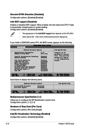
... support: [Disabled] [Disabled] F1:Help ESC: Exit ↑↓ : Select Item →← : Select Menu -/+: Change Value Enter: Select SubMenu Item Specific Help F5: Setup Defaults F10: Save and Exit Multiprocessor Specification [1.4] Allows you install a 5200/5400 series CPU, the BIOS screen appears as the following. Configuration options: [1.1] [1.4] Numbers of Stop Grant [1.4] [Per Core] Intel(R) Virtualization Technology [Enabled] Machine Checking [Enabled] Fast String Operations Compatible FPU Code Split Lock operations Thermal Management...
... support: [Disabled] [Disabled] F1:Help ESC: Exit ↑↓ : Select Item →← : Select Menu -/+: Change Value Enter: Select SubMenu Item Specific Help F5: Setup Defaults F10: Save and Exit Multiprocessor Specification [1.4] Allows you install a 5200/5400 series CPU, the BIOS screen appears as the following. Configuration options: [1.1] [1.4] Numbers of Stop Grant [1.4] [Per Core] Intel(R) Virtualization Technology [Enabled] Machine Checking [Enabled] Fast String Operations Compatible FPU Code Split Lock operations Thermal Management...

User Manual
Page 80
... Snooping [Disabled] When set to [Yes] and if you to clear the Extended System Configuration Data (ESCD) area. Advanced PhoenixBIOS Setup Utility Option ROM Scan: PCIX1 Slot [Enabled] Item Specific Help Initialize device expansion ROM Option ROM Scan [Enabled] Allows you want to configure the specific PCI devices. PCIE4-5 Slot Allows you install a Plug and Play operating system, the operating system configures the Plug and Play devices not required for boot. When set to [No], BIOS configures all the devices in the...
... Snooping [Disabled] When set to [Yes] and if you to clear the Extended System Configuration Data (ESCD) area. Advanced PhoenixBIOS Setup Utility Option ROM Scan: PCIX1 Slot [Enabled] Item Specific Help Initialize device expansion ROM Option ROM Scan [Enabled] Allows you want to configure the specific PCI devices. PCIE4-5 Slot Allows you install a Plug and Play operating system, the operating system configures the Plug and Play devices not required for boot. When set to [No], BIOS configures all the devices in the...
User Manual
Page 81
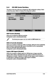
.... Configuration options: [Disabled] [Enabled] ASUS RS520-X5/PS8 5-23 F1 Help ESC Exit ↑↓ Select Item →← Select Menu -/+ Change Values F9 Setup Defaults Enter Select Sub-Menu F10 Save and Exit USB Function [Enabled] Allows you enable the USB Function item. If detected, the USB controller legacy mode is disabled. 5.4.4 ICH USB Control Sub-Menu The items in this item to [Enabled] allows the built-in high speed USB support in the BIOS to turn on legacy operating...
.... Configuration options: [Disabled] [Enabled] ASUS RS520-X5/PS8 5-23 F1 Help ESC Exit ↑↓ Select Item →← Select Menu -/+ Change Values F9 Setup Defaults Enter Select Sub-Menu F10 Save and Exit USB Function [Enabled] Allows you enable the USB Function item. If detected, the USB controller legacy mode is disabled. 5.4.4 ICH USB Control Sub-Menu The items in this item to [Enabled] allows the built-in high speed USB support in the BIOS to turn on legacy operating...

User Manual
Page 82
...COM2 port. Advanced PhoenixBIOS Setup Utility Peripheral Devices Configuration Item Specific Help COM1 port: Base I/O address: Interrupt: COM2 port: Mode: Base I/O address: Interrupt: Parallel port: Base I/O address: Interrupt: Mode: DMA channel Floppy disk controller [Enabled] [3F8] [IRQ 4] [Enabled] [Normal] [2F8] [IRQ 3] [Enabled] [378] [IRQ 7] [ECP] [DMA 3] [Enabled] Confugure COM1 port using options: [Disabled] No configuration [Enabled] User configuration [Auto] BIOS or OS chooses configuration (OS Controlled) Displayed when...
...COM2 port. Advanced PhoenixBIOS Setup Utility Peripheral Devices Configuration Item Specific Help COM1 port: Base I/O address: Interrupt: COM2 port: Mode: Base I/O address: Interrupt: Parallel port: Base I/O address: Interrupt: Mode: DMA channel Floppy disk controller [Enabled] [3F8] [IRQ 4] [Enabled] [Normal] [2F8] [IRQ 3] [Enabled] [378] [IRQ 7] [ECP] [DMA 3] [Enabled] Confugure COM1 port using options: [Disabled] No configuration [Enabled] User configuration [Auto] BIOS or OS chooses configuration (OS Controlled) Displayed when...

User Manual
Page 92
...; Select Menu -/+ Change Values F9 Setup Defaults Enter Select Sub-Menu F10 Save and Exit 5-34 Chapter 5: BIOS setup Press . Confirm the password by typing the exact characters again, then press . 5.6 Security menu Main Advanced PhoenixBIOS Setup Utility Server Security Boot Supervisor Password Is: User Password Is: Set Supervisor Password Set User Password Password Check Password Lock Mode Removable Device Boot Flash Write Clear Clear [Enter] [Enter] [Setup] [Disabled] [Enabled] [Enabled] Exit Item Specific Help Supervisor Password controls access to the setup utility.
...; Select Menu -/+ Change Values F9 Setup Defaults Enter Select Sub-Menu F10 Save and Exit 5-34 Chapter 5: BIOS setup Press . Confirm the password by typing the exact characters again, then press . 5.6 Security menu Main Advanced PhoenixBIOS Setup Utility Server Security Boot Supervisor Password Is: User Password Is: Set Supervisor Password Set User Password Password Check Password Lock Mode Removable Device Boot Flash Write Clear Clear [Enter] [Enter] [Setup] [Disabled] [Enabled] [Enabled] Exit Item Specific Help Supervisor Password controls access to the setup utility.

User Manual
Page 93
... the BIOS Setup and the system. The RAM data containing the password information is locked and the user has no privilege to enter the BIOS Setup program preventing unauthorized access. Select [Always] to Clear. Configuration options: [Setup] [Always] Password Lock Mode [Enabled] When set to [Enabled], the keyboard is powered by erasing the CMOS Real Time Clock (RTC) RAM. A note about passwords The Supervisor password is required to section "4.2 Jumpers" for instructions. Configuration options: [Disabled] [Enabled] ASUS RS520-X5/PS8...
... the BIOS Setup and the system. The RAM data containing the password information is locked and the user has no privilege to enter the BIOS Setup program preventing unauthorized access. Select [Always] to Clear. Configuration options: [Setup] [Always] Password Lock Mode [Enabled] When set to [Enabled], the keyboard is powered by erasing the CMOS Real Time Clock (RTC) RAM. A note about passwords The Supervisor password is required to section "4.2 Jumpers" for instructions. Configuration options: [Disabled] [Enabled] ASUS RS520-X5/PS8...

User Manual
Page 100
... supports Serial ATA hard disk drives and RAID0, RAID1, RAID0+1 and RAID5 configurations. • LSI1068 PCI-X SAS controller supports SAS disk drives and RAID0, RAID1, and RAID1E configuration. 6.1.1 RAID definitions RAID 0 (Data striping) optimizes two identical hard disk drives to the entire system. Among the advantages of a single disk alone, thus improving data access and storage. Use of both data and parity information across three or more hard disk drives for this setup. If you want to boot the system from a hard disk drive...
... supports Serial ATA hard disk drives and RAID0, RAID1, RAID0+1 and RAID5 configurations. • LSI1068 PCI-X SAS controller supports SAS disk drives and RAID0, RAID1, and RAID1E configuration. 6.1.1 RAID definitions RAID 0 (Data striping) optimizes two identical hard disk drives to the entire system. Among the advantages of a single disk alone, thus improving data access and storage. Use of both data and parity information across three or more hard disk drives for this setup. If you want to boot the system from a hard disk drive...

User Manual
Page 101
..., use the LSI1068 SAS Configuration Utility if you can create a RAID set using the utilities embedded in each RAID configuration utility. For optimal performance, install identical drives of the same model and capacity when creating a disk array. 6.1.3 Setting the RAID item in BIOS You must set the RAID item in the BIOS Setup before you installed SAS hard disk drives to the mini-SAS connector(s) supported by the LSI1068 PCI-X SAS controller. Go to [Enhanced], then press . 4. ASUS RS520-X5/PS8 6-3 Refer to the succeeding sections for RAID set from SATA hard disk drives...
..., use the LSI1068 SAS Configuration Utility if you can create a RAID set using the utilities embedded in each RAID configuration utility. For optimal performance, install identical drives of the same model and capacity when creating a disk array. 6.1.3 Setting the RAID item in BIOS You must set the RAID item in the BIOS Setup before you installed SAS hard disk drives to the mini-SAS connector(s) supported by the LSI1068 PCI-X SAS controller. Go to [Enhanced], then press . 4. ASUS RS520-X5/PS8 6-3 Refer to the succeeding sections for RAID set from SATA hard disk drives...

User Manual
Page 109
... and reset other RAID set drive. Press to reset the drive or press to return to non-RAID. Follow steps 2 to 4 to reset the RAID set drives. 6.2.7 Exiting the Intel® Matrix Storage Manager To exit the utility: 1. Reset Disks to Non-RAID, then press to display this screen. [ RESET RAID DATA ] Resetting RAID data will revert back to highlight the RAID set hard disk drive: 1. ASUS RS520-X5/PS8 6-11 By removing these structures, the drive will remove internal RAID structures from the selected RAID disks. Resetting a RAID volume hard disk drive deletes all data...
... and reset other RAID set drive. Press to reset the drive or press to return to non-RAID. Follow steps 2 to 4 to reset the RAID set drives. 6.2.7 Exiting the Intel® Matrix Storage Manager To exit the utility: 1. Reset Disks to Non-RAID, then press to display this screen. [ RESET RAID DATA ] Resetting RAID data will revert back to highlight the RAID set hard disk drive: 1. ASUS RS520-X5/PS8 6-11 By removing these structures, the drive will remove internal RAID structures from the selected RAID disks. Resetting a RAID volume hard disk drive deletes all data...
User Manual
Page 135
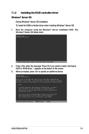
... additional SCSI adapters, DVD-ROM drives, or special disk controllers for use with Windows, including those for use with Windows, press ENTER. When prompted, press to install a third party SCSI or RAID driver... 2. S=Specify Additional Device ENTER=Continue F3=Exit ASUS RS520-X5/PS8 7-5 Press when the message "Press F6 if you have a device support disk from a mass storage device manufacturer, or do not have any device support disks from a mass storage device manufacturer, press S. * If you need to manually specify an adapter. Windows Setup Setup...
... additional SCSI adapters, DVD-ROM drives, or special disk controllers for use with Windows, including those for use with Windows, press ENTER. When prompted, press to install a third party SCSI or RAID driver... 2. S=Specify Additional Device ENTER=Continue F3=Exit ASUS RS520-X5/PS8 7-5 Press when the message "Press F6 if you have a device support disk from a mass storage device manufacturer, or do not have any device support disks from a mass storage device manufacturer, press S. * If you need to manually specify an adapter. Windows Setup Setup...


