
Users Manual English
Page 3
......v About this guide...vi ROG STRIX X570-E GAMING specifications summary viii Package contents...xii Installation tools and components xiii Chapter 1: Product Introduction 1.1 Motherboard overview 1-1 1.1.1 Before you proceed 1-1 1.1.2 Motherboard layout 1-2 1.1.3 Central Processing Unit (CPU 1-4 1.1.4 System memory 1-4 1.1.5 Expansion slots 1-6 1.1.6 Onboard LEDs 1-8 1.1.7 Headers 1-10 1.1.8 Internal connectors 1-13 Chapter 2: Basic Installation 2.1 Building your PC system 2-1 2.1.1 Motherboard installation 2-1 2.1.2 CPU installation 2-3 2.1.3 CPU heatsink and...
......v About this guide...vi ROG STRIX X570-E GAMING specifications summary viii Package contents...xii Installation tools and components xiii Chapter 1: Product Introduction 1.1 Motherboard overview 1-1 1.1.1 Before you proceed 1-1 1.1.2 Motherboard layout 1-2 1.1.3 Central Processing Unit (CPU 1-4 1.1.4 System memory 1-4 1.1.5 Expansion slots 1-6 1.1.6 Onboard LEDs 1-8 1.1.7 Headers 1-10 1.1.8 Internal connectors 1-13 Chapter 2: Basic Installation 2.1 Building your PC system 2-1 2.1.1 Motherboard installation 2-1 2.1.2 CPU installation 2-3 2.1.3 CPU heatsink and...

Users Manual English
Page 5
.... • Ensure that your power supply is broken, do not try to the correct voltage in any damage, contact your retailer. Operation safety • Before installing the motherboard and adding devices on a stable surface. • If you detect any area where it may become wet. • Place the product on it...
.... • Ensure that your power supply is broken, do not try to the correct voltage in any damage, contact your retailer. Operation safety • Before installing the motherboard and adding devices on a stable surface. • If you detect any area where it may become wet. • Place the product on it...

Users Manual English
Page 6
... contains the information you have been added by your dealer. Detailed descriptions of the switches, jumpers, and connectors on ASUS hardware and software products. 2. ASUS website The ASUS website (www.asus.com) provides updated information on the motherboard. • Chapter 2: Basic Installation This chapter lists the hardware setup procedures that may have to perform when...
... contains the information you have been added by your dealer. Detailed descriptions of the switches, jumpers, and connectors on ASUS hardware and software products. 2. ASUS website The ASUS website (www.asus.com) provides updated information on the motherboard. • Chapter 2: Basic Installation This chapter lists the hardware setup procedures that may have to perform when...

Users Manual English
Page 13
xiii Installation tools and components 1 Bag of screws Phillips (cross) screwdriver PC chassis Power supply unit AMD AM4 CPU AMD AM4/AM3 compatible CPU Fan DDR4 DIMM SATA hard disk drive SATA optical disc drive (optional) Graphics card (optional) The tools and components in the table above are not included in the motherboard package.
xiii Installation tools and components 1 Bag of screws Phillips (cross) screwdriver PC chassis Power supply unit AMD AM4 CPU AMD AM4/AM3 compatible CPU Fan DDR4 DIMM SATA hard disk drive SATA optical disc drive (optional) Graphics card (optional) The tools and components in the table above are not included in the motherboard package.
Users Manual English
Page 15
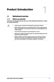
... is detached from the power supply. Chapter 1 Chapter 1: Product Introduction Product Introduction 1 1.1 Motherboard overview 1.1.1 Before you proceed Take note of the following precautions before you install motherboard components or change any motherboard settings. • Unplug the power cord from the wall socket before touching any component. • Before handling components, use... as the power supply case, to avoid damaging them due to static electricity. • Hold components by the edges to the motherboard, peripherals, or components. ASUS ROG STRIX X570-E GAMING 1-1
... is detached from the power supply. Chapter 1 Chapter 1: Product Introduction Product Introduction 1 1.1 Motherboard overview 1.1.1 Before you proceed Take note of the following precautions before you install motherboard components or change any motherboard settings. • Unplug the power cord from the wall socket before touching any component. • Before handling components, use... as the power supply case, to avoid damaging them due to static electricity. • Hold components by the edges to the motherboard, peripherals, or components. ASUS ROG STRIX X570-E GAMING 1-1

Users Manual English
Page 18
Chapter 1 STRIX X570-e GAMING ROG STRIX X570-E GAMING CPU socket AM4 The AM4 socket has a different pinout design. A DDR4 module is notched differently from a DDR, DDR2, or DDR3 module. Ensure that you use a ... with Radeon™ Vega Graphics Processors. DO NOT install a DDR, DDR2, or DDR3 memory module to prevent bending the connectors on the socket and damaging the CPU! DO NOT force the CPU into the socket to the DDR4 slot. DIMM_B1 DIMM_B2* DIMM_A1 DIMM_A2* STRIX X570-e GAMING ROG STRIX X570-E GAMING 288-pin DDR4 DIMM sockets 1-4 Chapter 1: Product Introduction...
Chapter 1 STRIX X570-e GAMING ROG STRIX X570-E GAMING CPU socket AM4 The AM4 socket has a different pinout design. A DDR4 module is notched differently from a DDR, DDR2, or DDR3 module. Ensure that you use a ... with Radeon™ Vega Graphics Processors. DO NOT install a DDR, DDR2, or DDR3 memory module to prevent bending the connectors on the socket and damaging the CPU! DO NOT force the CPU into the socket to the DDR4 slot. DIMM_B1 DIMM_B2* DIMM_A1 DIMM_A2* STRIX X570-e GAMING ROG STRIX X570-E GAMING 288-pin DDR4 DIMM sockets 1-4 Chapter 1: Product Introduction...

Users Manual English
Page 19
... stability, use a more efficient memory cooling system to support a full memory load (4 DIMMs) or overclocking condition. • Always install the DIMMS with the vendor to get the correct memory modules. Any excess memory from the higher-sized channel is then mapped for single... from the same vendor. For an optimum compatibility, we recommend that you install memory modules of the same version or data code (D/C) from a memory module. Check with the same CAS Latency. ASUS ROG STRIX X570-E GAMING 1-5 Under the default state, some memory modules for the dual-channel configuration...
... stability, use a more efficient memory cooling system to support a full memory load (4 DIMMs) or overclocking condition. • Always install the DIMMS with the vendor to get the correct memory modules. Any excess memory from the higher-sized channel is then mapped for single... from the same vendor. For an optimum compatibility, we recommend that you install memory modules of the same version or data code (D/C) from a memory module. Check with the same CAS Latency. ASUS ROG STRIX X570-E GAMING 1-5 Under the default state, some memory modules for the dual-channel configuration...
Users Manual English
Page 25
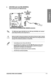
STRIX X570-e GAMING A RGB_HEADER1 A PIN 1 +12V G R B B RGB_HEADER2 PIN 1 +12V G R B B ROG STRIX X570-E GAMING RGB_HEADER connectors The RGB header supports 5050 RGB multi-color LED strips (12V/G/R/B), with the 12V header on the motherboard. • The .... • The LED strip is purchased separately. Before you install or remove any component, ensure that the ATX power supply is switched off or the power cord is aligned with a maximum power rating of 3A (12V), and no longer than 3 m. ASUS ROG STRIX X570-E GAMING 1-11 Chapter 1 2. AURA RGB header (4-pin RGB_HEADER1/2) These...
STRIX X570-e GAMING A RGB_HEADER1 A PIN 1 +12V G R B B RGB_HEADER2 PIN 1 +12V G R B B ROG STRIX X570-E GAMING RGB_HEADER connectors The RGB header supports 5050 RGB multi-color LED strips (12V/G/R/B), with the 12V header on the motherboard. • The .... • The LED strip is purchased separately. Before you install or remove any component, ensure that the ATX power supply is switched off or the power cord is aligned with a maximum power rating of 3A (12V), and no longer than 3 m. ASUS ROG STRIX X570-E GAMING 1-11 Chapter 1 2. AURA RGB header (4-pin RGB_HEADER1/2) These...

Users Manual English
Page 26
... RGB LED strip is detached from the power supply. STRIX X570-e GAMING ADD_GEN2_1 Ground Data +5V PIN 1 ADD_GEN2_2 PIN 1 +5V Data Ground ROG STRIX X570-E GAMING ADD_HEADER headers The addressable RGB header supports WS2812B addressable RGB LED strips (5V/Data/ Ground), with embedded WS2811LED driver ICs. Before you install or remove any component, ensure that the ATX power...
... RGB LED strip is detached from the power supply. STRIX X570-e GAMING ADD_GEN2_1 Ground Data +5V PIN 1 ADD_GEN2_2 PIN 1 +5V Data Ground ROG STRIX X570-E GAMING ADD_HEADER headers The addressable RGB header supports WS2812B addressable RGB LED strips (5V/Data/ Ground), with embedded WS2811LED driver ICs. Before you install or remove any component, ensure that the ATX power...

Users Manual English
Page 28
If you installed Serial ATA hard disk drives, you ...These connectors connect to section SATA Configuration for details. 1-14 Chapter 1: Product Introduction STRIX X570-e GAMING SATA6G_1 GND RSATA_TXP1 RSATA_TXN1 GND RSATA_RXN1 RSATA_RXP1 GND SATA6G_2 GND RSATA_TXP2 RSATA_TXN2 GND RSATA_RXN2 RSATA_RXP2 ...RSATA_RXN6 RSATA_RXP6 GND SATA6G_7 GND RSATA_TXP7 RSATA_TXN7 GND RSATA_RXN7 RSATA_RXP7 GND SATA6G_8 GND RSATA_TXP8 RSATA_TXN8 GND RSATA_RXN8 RSATA_RXP8 GND ROG STRIX X570-E GAMING SATA 6 Gb/s connectors • These connectors are set the SATA Mode in the motherboard support DVD....
If you installed Serial ATA hard disk drives, you ...These connectors connect to section SATA Configuration for details. 1-14 Chapter 1: Product Introduction STRIX X570-e GAMING SATA6G_1 GND RSATA_TXP1 RSATA_TXN1 GND RSATA_RXN1 RSATA_RXP1 GND SATA6G_2 GND RSATA_TXP2 RSATA_TXN2 GND RSATA_RXN2 RSATA_RXP2 ...RSATA_RXN6 RSATA_RXP6 GND SATA6G_7 GND RSATA_TXP7 RSATA_TXN7 GND RSATA_RXN7 RSATA_RXP7 GND SATA6G_8 GND RSATA_TXP8 RSATA_TXN8 GND RSATA_RXN8 RSATA_RXP8 GND ROG STRIX X570-E GAMING SATA 6 Gb/s connectors • These connectors are set the SATA Mode in the motherboard support DVD....

Users Manual English
Page 29
...VBUS TX2+ TX2GND RX2+ RX2GND DD+ CC2 ROG STRIX X570-E GAMING USB3.2 Gen2 front panel connector The USB 3.2 Gen2 module is purchased separately. GND IntA_P1_SSTX+ IntA_P1_SSTX- GND IntA_P1_SSRX+ IntA_P1_SSRX- STRIX X570-e GAMING IntA_P2_D+ IntA_P2_DGND IntA_P2_SSTX+ IntA_P2_SSTXGND IntA_P2_SSRX+ IntA_P2_SSRXVbus ... data transfer speeds of up to 10 Gbps. Vbus ROG STRIX X570-E GAMING USB 3.2 Gen1 connectors The USB 3.2 Gen1 module is purchased separately. 4. ASUS ROG STRIX X570-E GAMING 1-15 Chapter 1 3. With an installed USB 3.2 Gen1 module, you to connect a USB ...
...VBUS TX2+ TX2GND RX2+ RX2GND DD+ CC2 ROG STRIX X570-E GAMING USB3.2 Gen2 front panel connector The USB 3.2 Gen2 module is purchased separately. GND IntA_P1_SSTX+ IntA_P1_SSTX- GND IntA_P1_SSRX+ IntA_P1_SSRX- STRIX X570-e GAMING IntA_P2_D+ IntA_P2_DGND IntA_P2_SSTX+ IntA_P2_SSTXGND IntA_P2_SSRX+ IntA_P2_SSRXVbus ... data transfer speeds of up to 10 Gbps. Vbus ROG STRIX X570-E GAMING USB 3.2 Gen1 connectors The USB 3.2 Gen1 module is purchased separately. 4. ASUS ROG STRIX X570-E GAMING 1-15 Chapter 1 3. With an installed USB 3.2 Gen1 module, you to connect a USB ...

Users Manual English
Page 30
...install the module to 480 Mb/s connection speed. These USB connectors comply with USB 2.0 specification that supports up to a slot opening at the back of the system chassis. STRIX X570-e GAMING USB34 USB12 USB+5V USB_P1USB_P1+ GND NC USB+5V USB_P3USB_P3+ GND NC USB+5V USB_P2USB_P2+ GND USB+5V USB_P4USB_P4+ GND PIN 1 PIN 1 ROG STRIX X570-E GAMING... USB2.0 connectors Never connect a 1394 cable to the USB connectors. LED connector (13-pin LED1_CON1) This connector is for USB 2.0 ports. STRIX X570-e GAMING LED1_CON ROG STRIX X570-E GAMING LED_CON 1-16...
...install the module to 480 Mb/s connection speed. These USB connectors comply with USB 2.0 specification that supports up to a slot opening at the back of the system chassis. STRIX X570-e GAMING USB34 USB12 USB+5V USB_P1USB_P1+ GND NC USB+5V USB_P3USB_P3+ GND NC USB+5V USB_P2USB_P2+ GND USB+5V USB_P4USB_P4+ GND PIN 1 PIN 1 ROG STRIX X570-E GAMING... USB2.0 connectors Never connect a 1394 cable to the USB connectors. LED connector (13-pin LED1_CON1) This connector is for USB 2.0 ports. STRIX X570-e GAMING LED1_CON ROG STRIX X570-E GAMING LED_CON 1-16...

Users Manual English
Page 34
M.2_2) These sockets allow you to install M.2 SSD modules. A M.2_1(SOCKET3) STRIX X570-e GAMING 22110 2280 2260 2242 B M.2_2(SOCKET3) A 22110 2280 2260 2242 B ROG STRIX X570-E GAMING M.2 sockets • For 3rd Generation AMD Ryzen™ processors, the M.2 socket 3 supports PCIe 4.0 x4 mode and SATA mode M ... socket 3 supports PCIe 3.0 x4 mode and SATA mode M Key design and type 2242 / 2260 / 2280 / 22110 storage devices. • For AMD X570 chipset, the M.2 socket 3 supports PCIe 4.0 x4 mode and SATA mode M Key design and type 2242/ 2260/ 2280 / 22110 storage devices. The M.2...
M.2_2) These sockets allow you to install M.2 SSD modules. A M.2_1(SOCKET3) STRIX X570-e GAMING 22110 2280 2260 2242 B M.2_2(SOCKET3) A 22110 2280 2260 2242 B ROG STRIX X570-E GAMING M.2 sockets • For 3rd Generation AMD Ryzen™ processors, the M.2 socket 3 supports PCIe 4.0 x4 mode and SATA mode M ... socket 3 supports PCIe 3.0 x4 mode and SATA mode M Key design and type 2242 / 2260 / 2280 / 22110 storage devices. • For AMD X570 chipset, the M.2 socket 3 supports PCIe 4.0 x4 mode and SATA mode M Key design and type 2242/ 2260/ 2280 / 22110 storage devices. The M.2...
Users Manual English
Page 37
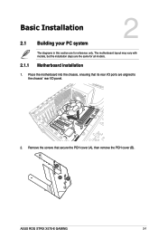
The motherboard layout may vary with models, but the installation steps are for all models. Chapter 2 ASUS ROG STRIX X570-E GAMING 2-1 Place the motherboard into the chassis, ensuring that secure the PCH cover (A), then remove the PCH cover (B). Motherboard installation 1. Remove the screws that its rear I/O ports are aligned to the chassis' rear I/O panel. 2. Chapter 2: Basic Installation Basic Installation 2.1 Building your PC system 2 2.1.1 The diagrams in this section are the same for reference only.
The motherboard layout may vary with models, but the installation steps are for all models. Chapter 2 ASUS ROG STRIX X570-E GAMING 2-1 Place the motherboard into the chassis, ensuring that secure the PCH cover (A), then remove the PCH cover (B). Motherboard installation 1. Remove the screws that its rear I/O ports are aligned to the chassis' rear I/O panel. 2. Chapter 2: Basic Installation Basic Installation 2.1 Building your PC system 2 2.1.1 The diagrams in this section are the same for reference only.

Users Manual English
Page 38
3. Chapter 2 4. Place nine (9) screws into the holes indicated by circles to secure the motherboard to the chassis. Doing so can damage the motherboard. 2-2 Chapter 2: Basic Installation Remove the screws that secure the M.2 heatsink (A), then remove the M.2 heatsink (B). STRIX X570-e GAMING DO NOT over tighten the screws!
3. Chapter 2 4. Place nine (9) screws into the holes indicated by circles to secure the motherboard to the chassis. Doing so can damage the motherboard. 2-2 Chapter 2: Basic Installation Remove the screws that secure the M.2 heatsink (A), then remove the M.2 heatsink (B). STRIX X570-e GAMING DO NOT over tighten the screws!
Users Manual English
Page 39
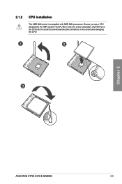
Ensure you use a CPU designed for the AM4 socket. The CPU fits in only one correct orientation. DO NOT force the CPU into the socket to prevent bending the connectors on the socket and damaging the CPU! 1 2 3 Chapter 2 ASUS ROG STRIX X570-E GAMING 2-3 2.1.2 CPU installation The AMD AM4 socket is compatible with AMD AM4 processors.
Ensure you use a CPU designed for the AM4 socket. The CPU fits in only one correct orientation. DO NOT force the CPU into the socket to prevent bending the connectors on the socket and damaging the CPU! 1 2 3 Chapter 2 ASUS ROG STRIX X570-E GAMING 2-3 2.1.2 CPU installation The AMD AM4 socket is compatible with AMD AM4 processors.

Users Manual English
Page 40
2.1.3 CPU heatsink and fan assembly installation Apply the Thermal Interface Material to the CPU heatsink and CPU before you install the heatsink and fan if necessary. CPU Heatsink and fan assembly Type 1 1 2 Chapter 2 3 5 2-4 4 Chapter 2: Basic Installation
2.1.3 CPU heatsink and fan assembly installation Apply the Thermal Interface Material to the CPU heatsink and CPU before you install the heatsink and fan if necessary. CPU Heatsink and fan assembly Type 1 1 2 Chapter 2 3 5 2-4 4 Chapter 2: Basic Installation
Users Manual English
Page 43
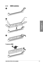
2.1.4 DIMM installation Chapter 2 To remove a DIMM ASUS ROG STRIX X570-E GAMING 2-7
2.1.4 DIMM installation Chapter 2 To remove a DIMM ASUS ROG STRIX X570-E GAMING 2-7

Users Manual English
Page 44
2.1.5 ATX power connection A B OR AND Chapter 2 • DO NOT connect the 4-pin power plug only, the motherboard may overheat under heavy usage. • Ensure to connect the 8-pin power plug, or connect both the 8-pin and 4-pin power plugs. 2.1.6 SATA device connection 3 4 5 6 3 4 5 6 2-8 OR Chapter 2: Basic Installation
2.1.5 ATX power connection A B OR AND Chapter 2 • DO NOT connect the 4-pin power plug only, the motherboard may overheat under heavy usage. • Ensure to connect the 8-pin power plug, or connect both the 8-pin and 4-pin power plugs. 2.1.6 SATA device connection 3 4 5 6 3 4 5 6 2-8 OR Chapter 2: Basic Installation
Users Manual English
Page 45
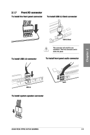
To install front panel audio connector USB 2.0 AAFP To install system speaker connector ASUS ROG STRIX X570-E GAMING 2-9 Chapter 2 2.1.7 Front I/O connector To install the front panel connector To install USB 3.2 Gen2 connector To install USB 2.0 connector USB 3.2 Gen2 This connector will only fit in one orientation. Push the connector until it clicks into place.
To install front panel audio connector USB 2.0 AAFP To install system speaker connector ASUS ROG STRIX X570-E GAMING 2-9 Chapter 2 2.1.7 Front I/O connector To install the front panel connector To install USB 3.2 Gen2 connector To install USB 2.0 connector USB 3.2 Gen2 This connector will only fit in one orientation. Push the connector until it clicks into place.


