
Users Manual English
Page 1
Motherboard ROG STRIX B550-E GAMING
Motherboard ROG STRIX B550-E GAMING
Users Manual English
Page 3
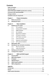
...ROG STRIX B550-E GAMING specifications summary vi Connectors with shared bandwidth x Package contents...xi Installation tools and components xii Chapter 1: Product Introduction 1.1 Before you proceed 1-1 1.2 Motherboard layout 1-2 Chapter 2: Basic Installation 2.1 Building your PC system 2-1 2.1.1 CPU installation 2-1 2.1.2 Cooling system installation 2-2 2.1.3 DIMM installation 2-5 2.1.4 M.2 installation 2-6 2.1.5 Motherboard...Wi-Fi antenna installation 2-13 2.2 BIOS update utility 2-14 2.3 Motherboard rear and audio connections 2-15 2.3.1 Rear I/O connection 2-15 ...
...ROG STRIX B550-E GAMING specifications summary vi Connectors with shared bandwidth x Package contents...xi Installation tools and components xii Chapter 1: Product Introduction 1.1 Before you proceed 1-1 1.2 Motherboard layout 1-2 Chapter 2: Basic Installation 2.1 Building your PC system 2-1 2.1.1 CPU installation 2-1 2.1.2 Cooling system installation 2-2 2.1.3 DIMM installation 2-5 2.1.4 M.2 installation 2-6 2.1.5 Motherboard...Wi-Fi antenna installation 2-13 2.2 BIOS update utility 2-14 2.3 Motherboard rear and audio connections 2-15 2.3.1 Rear I/O connection 2-15 ...

Users Manual English
Page 4
... system before you encounter technical problems with the product, contact a qualified service technician or your retailer. • Your motherboard should only be used in your dealer immediately. • To avoid short circuits, keep paper clips, screws, and staples away from the... power cables for the devices are unplugged before the signal cables are using an adapter or extension cord. Operation safety • Before installing the motherboard and adding devices on a stable surface. • If you add a device. • Before connecting or removing signal cables from connectors, ...
... system before you encounter technical problems with the product, contact a qualified service technician or your retailer. • Your motherboard should only be used in your dealer immediately. • To avoid short circuits, keep paper clips, screws, and staples away from the... power cables for the devices are unplugged before the signal cables are using an adapter or extension cord. Operation safety • Before installing the motherboard and adding devices on a stable surface. • If you add a device. • Before connecting or removing signal cables from connectors, ...

Users Manual English
Page 5
... Refer to the following symbols used in this guide This user guide contains the information you need when installing and configuring the motherboard. v Optional documentation Your product package may have to perform when installing system components. • Chapter 3: BIOS and RAID ...Support This chapter tells how to complete a task. ASUS website The ASUS website (www.asus.com) provides updated information on RAID. IMPORTANT: Instructions that may include optional documentation, such as warranty flyers, that you...
... Refer to the following symbols used in this guide This user guide contains the information you need when installing and configuring the motherboard. v Optional documentation Your product package may have to perform when installing system components. • Chapter 3: BIOS and RAID ...Support This chapter tells how to complete a task. ASUS website The ASUS website (www.asus.com) provides updated information on RAID. IMPORTANT: Instructions that may include optional documentation, such as warranty flyers, that you...
Users Manual English
Page 11
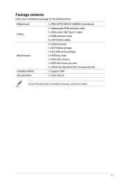
Package contents Check your motherboard package for the following items. Motherboard Cables Miscellaneous Installation Media Documentation 1 x ROG STRIX B550-E GAMING motherboard 1 x Addressable RGB extension cable 1 x ROG audio USB Type-C® cable 1 x RGB extension cable 4 x SATA 6Gb/s cables 1 x Cable ties pack 1 x M.2 Rubber package 1 x M.2 SSD screw package 1 x ROG key chain 1 x ROG Strix stickers 1 x ROG Strix thank you card 1 x ASUS 2x2 dual band Wi-Fi moving antennas 1 x Support DVD 1 x User manual If any of the above items is damaged or missing, contact your retailer. xi
Package contents Check your motherboard package for the following items. Motherboard Cables Miscellaneous Installation Media Documentation 1 x ROG STRIX B550-E GAMING motherboard 1 x Addressable RGB extension cable 1 x ROG audio USB Type-C® cable 1 x RGB extension cable 4 x SATA 6Gb/s cables 1 x Cable ties pack 1 x M.2 Rubber package 1 x M.2 SSD screw package 1 x ROG key chain 1 x ROG Strix stickers 1 x ROG Strix thank you card 1 x ASUS 2x2 dual band Wi-Fi moving antennas 1 x Support DVD 1 x User manual If any of the above items is damaged or missing, contact your retailer. xi

Users Manual English
Page 12
xii Installation tools and components Phillips (cross) screwdriver PC chassis Power supply unit AMD AM4 CPU AMD AM4/AM3 compatible CPU Fan DDR4 DIMM SATA hard disk drive SATA optical disc drive (optional) Graphics card (optional) M.2 SSD module (optional) 1 Bag of screws The tools and components in the table above are not included in the motherboard package.
xii Installation tools and components Phillips (cross) screwdriver PC chassis Power supply unit AMD AM4 CPU AMD AM4/AM3 compatible CPU Fan DDR4 DIMM SATA hard disk drive SATA optical disc drive (optional) Graphics card (optional) M.2 SSD module (optional) 1 Bag of screws The tools and components in the table above are not included in the motherboard package.

Users Manual English
Page 13
... Product Introduction Product Introduction 1 1.1 Before you proceed Take note of the following precautions before you install motherboard components or change any motherboard settings. • Unplug the power cord from the wall socket before touching any component. • ...power supply case, to avoid damaging them due to static electricity. • Hold components by the edges to the motherboard, peripherals, or components. Failure to do so may cause severe damage to avoid touching the ICs on them. ... or the power cord is detached from the power supply. ROG STRIX B550-E GAMING 1-1
... Product Introduction Product Introduction 1 1.1 Before you proceed Take note of the following precautions before you install motherboard components or change any motherboard settings. • Unplug the power cord from the wall socket before touching any component. • ...power supply case, to avoid damaging them due to static electricity. • Hold components by the edges to the motherboard, peripherals, or components. Failure to do so may cause severe damage to avoid touching the ICs on them. ... or the power cord is detached from the power supply. ROG STRIX B550-E GAMING 1-1

Users Manual English
Page 14
Chapter 1 1.2 Motherboard layout 5 4 21 FLBK_LED1 BIOS_FLBK USB_E5-8 EATX12V_2 EATX12V_1 1 24.4cm(9.6in) U32G2_C7 15 LAN_U32G2_34 HDMI _DP Intel® I225-V M.2(WIFI) LED1_CON CHA_FAN1 M.2_1(SOCKET3) ...module) DDR4 DIMM_A1 (64bit, 288-pin module) DDR4 DIMM_A2* (64bit, 288-pin module) 5 9 8 U32G1_12 USB3.2_7 30.5cm(12in) 3 Super I/O PCIEX1_1 BATTERY AMD B550 6 M.2_2(SOCKET3) SATA6G_56 SATA6G_34 SATA6G_12 PCIEX16_2 7 PCIEX1_2 TPU 22110 2280 2260 2242 PCIEX16_3 ARUR SPDIF_OUT CHA_FAN2 ADD GEN 2_2CHA_FAN3 T_SENSOR AAFP Q_CODE RGB_HEADER2 TB_HEADER USB_E34...
Chapter 1 1.2 Motherboard layout 5 4 21 FLBK_LED1 BIOS_FLBK USB_E5-8 EATX12V_2 EATX12V_1 1 24.4cm(9.6in) U32G2_C7 15 LAN_U32G2_34 HDMI _DP Intel® I225-V M.2(WIFI) LED1_CON CHA_FAN1 M.2_1(SOCKET3) ...module) DDR4 DIMM_A1 (64bit, 288-pin module) DDR4 DIMM_A2* (64bit, 288-pin module) 5 9 8 U32G1_12 USB3.2_7 30.5cm(12in) 3 Super I/O PCIEX1_1 BATTERY AMD B550 6 M.2_2(SOCKET3) SATA6G_56 SATA6G_34 SATA6G_12 PCIEX16_2 7 PCIEX1_2 TPU 22110 2280 2260 2242 PCIEX16_3 ARUR SPDIF_OUT CHA_FAN2 ADD GEN 2_2CHA_FAN3 T_SENSOR AAFP Q_CODE RGB_HEADER2 TB_HEADER USB_E34...

Users Manual English
Page 16
SOCKET AM4 The AM4 socket has a different pinout design. DO NOT force the CPU into the socket to prevent bending the connectors on the socket and damaging the CPU! Ensure that you use a CPU designed for 3rd Gen AMD Ryzen™ Processors. CPU socket The motherboard comes with an AMD Socket AM4 for the AM4 socket. Chapter 1 1. Ensure that all power cables are unplugged before installing the CPU. 1-4 Chapter 1: Product Introduction The CPU fits in only one correct orientation.
SOCKET AM4 The AM4 socket has a different pinout design. DO NOT force the CPU into the socket to prevent bending the connectors on the socket and damaging the CPU! Ensure that you use a CPU designed for 3rd Gen AMD Ryzen™ Processors. CPU socket The motherboard comes with an AMD Socket AM4 for the AM4 socket. Chapter 1 1. Ensure that all power cables are unplugged before installing the CPU. 1-4 Chapter 1: Product Introduction The CPU fits in only one correct orientation.

Users Manual English
Page 17
DIMM slots The motherboard comes with Dual Inline Memory Modules (DIMM) slots designed for DDR4 (Double Data Rate 4) memory modules. A DDR4 memory module is notched differently from a DDR, DDR2, or DDR3 module. Recommended memory configurations ROG STRIX B550-E GAMING 1-5 DIMM_B1 DIMM_B2* DIMM_A1 DIMM_A2* Chapter 1 2. DO NOT install a DDR, DDR2, or DDR3 memory module to the DDR4 slot.
DIMM slots The motherboard comes with Dual Inline Memory Modules (DIMM) slots designed for DDR4 (Double Data Rate 4) memory modules. A DDR4 memory module is notched differently from a DDR, DDR2, or DDR3 module. Recommended memory configurations ROG STRIX B550-E GAMING 1-5 DIMM_B1 DIMM_B2* DIMM_A1 DIMM_A2* Chapter 1 2. DO NOT install a DDR, DDR2, or DDR3 memory module to the DDR4 slot.
Users Manual English
Page 19
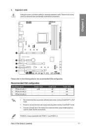
Dual VGA x8 x8 - Triple VGA x8 x8 x4 • We recommend that you physical injury and damage motherboard components. 3. PCIe 4.0 x16_1 3. PCIEX16_3 shares bandwidth with PCIEX1_1 and PCIEX1_2. PCIe 4.0 x16_2 5. Chapter 1 1 PCIEX16_1 2 PCIEX1_1 3 PCIEX16_2 4 PCIEX1_2 5... recommended VGA configuration. Failure to the following table for better thermal environment. PCIe 3.0 x16_3 Single VGA x16 - ROG STRIX B550-E GAMING 1-7 Recommended VGA configuration Slot Description 1. Expansion slots Unplug the power cord before adding or removing expansion cards.
Dual VGA x8 x8 - Triple VGA x8 x8 x4 • We recommend that you physical injury and damage motherboard components. 3. PCIe 4.0 x16_1 3. PCIEX16_3 shares bandwidth with PCIEX1_1 and PCIEX1_2. PCIe 4.0 x16_2 5. Chapter 1 1 PCIEX16_1 2 PCIEX1_1 3 PCIEX16_2 4 PCIEX1_2 5... recommended VGA configuration. Failure to the following table for better thermal environment. PCIe 3.0 x16_3 Single VGA x16 - ROG STRIX B550-E GAMING 1-7 Recommended VGA configuration Slot Description 1. Expansion slots Unplug the power cord before adding or removing expansion cards.
Users Manual English
Page 21
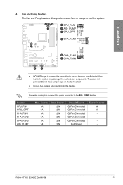
... Controlled Q-Fan Controlled Q-Fan Controlled Q-Fan Controlled Full-Speed Shared Control A A - These are not jumpers! Insufficient air flow inside the system may damage the motherboard components. ROG STRIX B550-E GAMING 1-9 Do not place jumper caps on the fan headers! • Ensure the cable is fully inserted into the header. Header CPU_FAN CPU_OPT CHA_FAN1 CHA_FAN2 CHA_FAN3...
... Controlled Q-Fan Controlled Q-Fan Controlled Q-Fan Controlled Full-Speed Shared Control A A - These are not jumpers! Insufficient air flow inside the system may damage the motherboard components. ROG STRIX B550-E GAMING 1-9 Do not place jumper caps on the fan headers! • Ensure the cable is fully inserted into the header. Header CPU_FAN CPU_OPT CHA_FAN1 CHA_FAN2 CHA_FAN3...

Users Manual English
Page 22
...PIN 1 GND +5 Volts +5 Volts +5 Volts -5 Volts GND GND GND PSON# GND -12 Volts +3 Volts • DO NOT connect the 4-pin power plug only, the motherboard may not boot up if the power is inadequate. • If you want to use two or more high-end PCI Express x16 cards, use...PSU) that complies with ATX 12V Specification 2.0 (or later version) and provides a minimum power of 350 W. • We recommend that you to connect your motherboard to fit in only one orientation, find the proper orientation and push down firmly until the power supply plugs are designed to a power supply. Chapter 1 5....
...PIN 1 GND +5 Volts +5 Volts +5 Volts -5 Volts GND GND GND PSON# GND -12 Volts +3 Volts • DO NOT connect the 4-pin power plug only, the motherboard may not boot up if the power is inadequate. • If you want to use two or more high-end PCI Express x16 cards, use...PSU) that complies with ATX 12V Specification 2.0 (or later version) and provides a minimum power of 350 W. • We recommend that you to connect your motherboard to fit in only one orientation, find the proper orientation and push down firmly until the power supply plugs are designed to a power supply. Chapter 1 5....

Users Manual English
Page 24
... SATA6G_6 A B C A GND RSATA_TXP B RSATA_TXN GND C RSATA_RXN RSATA_RXP GND GND RSATA_TXP RSATA_TXN GND RSATA_RXN RSATA_RXP GND • These connectors are set the SATA Mode in the motherboard support DVD. • When using NCQ, set to connect SATA devices such as optical disc drives and hard disk drives via a SATA cable. Chapter 1 7.
... SATA6G_6 A B C A GND RSATA_TXP B RSATA_TXN GND C RSATA_RXN RSATA_RXP GND GND RSATA_TXP RSATA_TXN GND RSATA_RXN RSATA_RXP GND • These connectors are set the SATA Mode in the motherboard support DVD. • When using NCQ, set to connect SATA devices such as optical disc drives and hard disk drives via a SATA cable. Chapter 1 7.

Users Manual English
Page 26
A USBE_34 B USBE_12 USB+5V USB_P1USB_P1+ GND NC USB+5V USB_P2USB_P2+ GND AB PIN 1 DO NOT connect a 1394 cable to 480 Mb/s. Chapter 1 10. The USB 2.0 header provides data transfer speeds of up to the USB connectors. Doing so will damage the motherboard! USB 2.0 header The USB 2.0 header allows you to connect a USB module for additional USB 2.0 ports. The USB 2.0 module is purchased separately. 1-14 Chapter 1: Product Introduction
A USBE_34 B USBE_12 USB+5V USB_P1USB_P1+ GND NC USB+5V USB_P2USB_P2+ GND AB PIN 1 DO NOT connect a 1394 cable to 480 Mb/s. Chapter 1 10. The USB 2.0 header provides data transfer speeds of up to the USB connectors. Doing so will damage the motherboard! USB 2.0 header The USB 2.0 header allows you to connect a USB module for additional USB 2.0 ports. The USB 2.0 module is purchased separately. 1-14 Chapter 1: Product Introduction

Users Manual English
Page 27
... cause severe damage to connect individually addressable RGB WS2812B LED strips or WS2812B based LED strips. Before you to the motherboard, peripherals, or components. • Actual lighting and color will vary with LED strip. • If your LED...motherboard. • The addressable RGB LED strip will only light up , check if the addressable RGB LED strip is connected in the correct orientation, and the 5V connector is aligned with a maximum power rating of 3A (5V), and the addressable headers on . • The addressable RGB LED strip is purchased separately. ROG STRIX B550-E GAMING...
... cause severe damage to connect individually addressable RGB WS2812B LED strips or WS2812B based LED strips. Before you to the motherboard, peripherals, or components. • Actual lighting and color will vary with LED strip. • If your LED...motherboard. • The addressable RGB LED strip will only light up , check if the addressable RGB LED strip is connected in the correct orientation, and the 5V connector is aligned with a maximum power rating of 3A (5V), and the addressable headers on . • The addressable RGB LED strip is purchased separately. ROG STRIX B550-E GAMING...

Users Manual English
Page 28
...PIN 1 +12V G R B B RGB_HEADER2 PIN 1 +12V G R B B The AURA RGB header supports 5050 RGB multi-color LED strips (12V/G/R/B), with the 12V header on the motherboard. • The LED strip will vary with LED strip. • If your LED strip does not light up when the system is powered on. • ...The LED strip is purchased separately. 1-16 Chapter 1: Product Introduction Before you to the motherboard, peripherals, or components. • Actual lighting and color will only light up , check if the RGB LED extension cable and the RGB LED ...
...PIN 1 +12V G R B B RGB_HEADER2 PIN 1 +12V G R B B The AURA RGB header supports 5050 RGB multi-color LED strips (12V/G/R/B), with the 12V header on the motherboard. • The LED strip will vary with LED strip. • If your LED strip does not light up when the system is powered on. • ...The LED strip is purchased separately. 1-16 Chapter 1: Product Introduction Before you to the motherboard, peripherals, or components. • Actual lighting and color will only light up , check if the RGB LED extension cable and the RGB LED ...

Users Manual English
Page 30
LED connector This connector is for connecting the LED strip on your back I /O module cable to avail of the front panel audio I /O cover. Chapter 1 We recommend that supports HD Audio. Front Panel Audio header The front panel audio header is for a chassis-mounted front panel audio I/O module that you connect a high-definition front panel audio module to this connector to this header. LED1_CON 1-18 Chapter 1: Product Introduction Connect one end of the motherboard's high-definition audio capability. 15. 14.
LED connector This connector is for connecting the LED strip on your back I /O module cable to avail of the front panel audio I /O cover. Chapter 1 We recommend that supports HD Audio. Front Panel Audio header The front panel audio header is for a chassis-mounted front panel audio I/O module that you connect a high-definition front panel audio module to this connector to this header. LED1_CON 1-18 Chapter 1: Product Introduction Connect one end of the motherboard's high-definition audio capability. 15. 14.

Users Manual English
Page 33
Connect the thermal sensor and place it on the device or the motherboard's component to monitor the temperature of the devices and the critical components inside the motherboard. ROG STRIX B550-E GAMING 1-21 Thermal Sensor header The Thermal Sensor header allows you to connect a sensor to detect its temperature. T_SENSOR PIN 1 The thermal sensor is purchased separately. SENSOR IN GND Chapter 1 19.
Connect the thermal sensor and place it on the device or the motherboard's component to monitor the temperature of the devices and the critical components inside the motherboard. ROG STRIX B550-E GAMING 1-21 Thermal Sensor header The Thermal Sensor header allows you to connect a sensor to detect its temperature. T_SENSOR PIN 1 The thermal sensor is purchased separately. SENSOR IN GND Chapter 1 19.

Users Manual English
Page 35
... (YELLOW) The Q-LEDs provide the most probable cause of an error code as a starting point for troubleshooting. ROG STRIX B550-E GAMING 1-23 Q-LEDs The Q-LEDs check key components (CPU, DRAM, VGA, and booting devices) during the motherboard booting process. The actual cause may vary from case to the Q-Code table in the Appendix section for...
... (YELLOW) The Q-LEDs provide the most probable cause of an error code as a starting point for troubleshooting. ROG STRIX B550-E GAMING 1-23 Q-LEDs The Q-LEDs check key components (CPU, DRAM, VGA, and booting devices) during the motherboard booting process. The actual cause may vary from case to the Q-Code table in the Appendix section for...


