
Users Manual English
Page 3
Contents Safety information...vi About this guide...vii ROG MAXIMUS XI FORMULA specifications summary ix Package contents...xiv Installation tools and components xv Chapter 1: Product...14 Chapter 2: Basic Installation 2.1 Building your PC system 2-1 2.1.1 CPU installation 2-1 2.1.2 Cooling system installation 2-2 2.1.3 Motherboard installation 2-5 2.1.4 DIMM installation 2-6 2.1.5 ATX power connection 2-7 2.1.6 SATA device connection 2-8 2.1.7 Front I/O connector 2-9 2.1.8 Expansion card installation 2-10 2.1.9 M.2 installation 2-12 2.1.10 Wi-Fi antenna installation ...
Contents Safety information...vi About this guide...vii ROG MAXIMUS XI FORMULA specifications summary ix Package contents...xiv Installation tools and components xv Chapter 1: Product...14 Chapter 2: Basic Installation 2.1 Building your PC system 2-1 2.1.1 CPU installation 2-1 2.1.2 Cooling system installation 2-2 2.1.3 Motherboard installation 2-5 2.1.4 DIMM installation 2-6 2.1.5 ATX power connection 2-7 2.1.6 SATA device connection 2-8 2.1.7 Front I/O connector 2-9 2.1.8 Expansion card installation 2-10 2.1.9 M.2 installation 2-12 2.1.10 Wi-Fi antenna installation ...
Users Manual English
Page 13
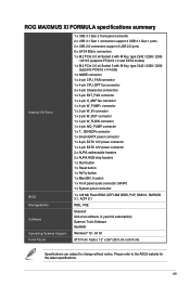
Please refer to change without notice. xiii ROG MAXIMUS XI FORMULA specifications summary Internal I/O Ports BIOS Manageability Software Operating System Support Form Factor 1 x USB 3.1 Gen 2 front panel connector 2 x USB 3.1 Gen 1 connectors support 4 USB 3.1 Gen 1 ports 2 x USB 2.0 ... AMI BIOS, PnP, DMI3.0, SM BIOS 3.1, ACPI 6.1 WOL, PXE Overwolf Anti-virus software (1-year full subscription) Daemon Tools Software WinRAR Windows® 10 - 64 bit ATX Form Factor, 12" x 9.6" (30.5 cm x 24.4 cm) Specifications are subject to the...
Please refer to change without notice. xiii ROG MAXIMUS XI FORMULA specifications summary Internal I/O Ports BIOS Manageability Software Operating System Support Form Factor 1 x USB 3.1 Gen 2 front panel connector 2 x USB 3.1 Gen 1 connectors support 4 USB 3.1 Gen 1 ports 2 x USB 2.0 ... AMI BIOS, PnP, DMI3.0, SM BIOS 3.1, ACPI 6.1 WOL, PXE Overwolf Anti-virus software (1-year full subscription) Daemon Tools Software WinRAR Windows® 10 - 64 bit ATX Form Factor, 12" x 9.6" (30.5 cm x 24.4 cm) Specifications are subject to the...
Users Manual English
Page 17
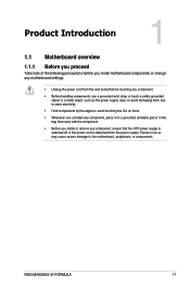
ROG MAXIMUS XI FORMULA 1-1 Chapter 1 Chapter 1: Product Introduction Product Introduction 1 1.1 Motherboard overview 1.1.1 Before you proceed Take note of the following precautions before you install or remove any component, ensure that the ATX power supply is switched off or the power cord is detached from the wall socket before touching any component. • Before handling components, use...
ROG MAXIMUS XI FORMULA 1-1 Chapter 1 Chapter 1: Product Introduction Product Introduction 1 1.1 Motherboard overview 1.1.1 Before you proceed Take note of the following precautions before you install or remove any component, ensure that the ATX power supply is switched off or the power cord is detached from the wall socket before touching any component. • Before handling components, use...
Users Manual English
Page 19
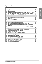
...1-18 1-25 1-5 1-24 1-13 1-9 1-9 1-15 1-16 1-14 1-23 1-21 1-17 1-10 1-17 1-19 1-11 1-15 1-26 1-22 1-22 1-23 ROG MAXIMUS XI FORMULA 1-3 Addressable RGB header (4-1 pin ADD_HEADER1-2) 5. USB1112) 18. M.2 sockets (M.2_1 (Socket 3); Fan and pump connectors (4-pin CPU_FAN; 4-pin CPU_OPT; 4-pin H_AMP; 5-pin...) 24. Chapter 1 Layout contents Connectors/Jumpers/Buttons and switches/Slots 1. Intel® Z390 Serial ATA 6 Gb/s connectors (7-pin SATA6G_12; ATX power connectors (24-pin EATXPWR; 8-pin EATX12V_1; 4-pin EATX12V_2) 2. RESET button (RESET) 10. II switch (MemOK!_II) 17. ...
...1-18 1-25 1-5 1-24 1-13 1-9 1-9 1-15 1-16 1-14 1-23 1-21 1-17 1-10 1-17 1-19 1-11 1-15 1-26 1-22 1-22 1-23 ROG MAXIMUS XI FORMULA 1-3 Addressable RGB header (4-1 pin ADD_HEADER1-2) 5. USB1112) 18. M.2 sockets (M.2_1 (Socket 3); Fan and pump connectors (4-pin CPU_FAN; 4-pin CPU_OPT; 4-pin H_AMP; 5-pin...) 24. Chapter 1 Layout contents Connectors/Jumpers/Buttons and switches/Slots 1. Intel® Z390 Serial ATA 6 Gb/s connectors (7-pin SATA6G_12; ATX power connectors (24-pin EATXPWR; 8-pin EATX12V_1; 4-pin EATX12V_2) 2. RESET button (RESET) 10. II switch (MemOK!_II) 17. ...
Users Manual English
Page 36
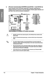
...8-pin and 4-pin power plugs. • For a fully configured system, we recommend that you use a power supply unit (PSU) that complies with ATX 12V Specification 2.0 (or later version) and provides a minimum power of 350 W. • We recommend that you want to use a PSU with more...PSU with a higher power output when configuring a system with 1000W power or above to fit these connectors in only one orientation. 9. ATX power connectors (24-pin EATXPWR; 8-pin EATX12V_1; 4-pin EATX12V_2) These connectors are designed to ensure the system stability. 1-20 Chapter 1: Product Introduction
...8-pin and 4-pin power plugs. • For a fully configured system, we recommend that you use a power supply unit (PSU) that complies with ATX 12V Specification 2.0 (or later version) and provides a minimum power of 350 W. • We recommend that you want to use a PSU with more...PSU with a higher power output when configuring a system with 1000W power or above to fit these connectors in only one orientation. 9. ATX power connectors (24-pin EATXPWR; 8-pin EATX12V_1; 4-pin EATX12V_2) These connectors are designed to ensure the system stability. 1-20 Chapter 1: Product Introduction
Users Manual English
Page 37
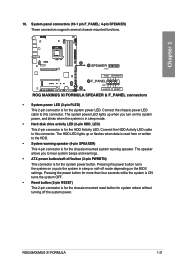
The speaker allows you turn on the BIOS settings. ROG MAXIMUS XI FORMULA 1-21 10. Connect the chassis power LED cable to hear system beeps and warnings. • ATX power button/soft-off button (2-pin PWRBTN) This connector is for the system power LED. Chapter 1 • System power LED (2-pin PLED) This 2-pin connector ...
The speaker allows you turn on the BIOS settings. ROG MAXIMUS XI FORMULA 1-21 10. Connect the chassis power LED cable to hear system beeps and warnings. • ATX power button/soft-off button (2-pin PWRBTN) This connector is for the system power LED. Chapter 1 • System power LED (2-pin PLED) This 2-pin connector ...
Users Manual English
Page 40
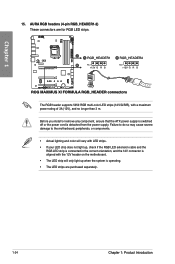
... 12V connector is aligned with a maximum power rating of 3A (12V), and no longer than 3 m. Before you install or remove any component, ensure that the ATX power supply is switched off or the power cord is operating. • The LED strips are for RGB LED strips. The RGB header supports 5050...
... 12V connector is aligned with a maximum power rating of 3A (12V), and no longer than 3 m. Before you install or remove any component, ensure that the ATX power supply is switched off or the power cord is operating. • The LED strips are for RGB LED strips. The RGB header supports 5050...
Users Manual English
Page 41
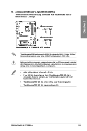
... strip is purchased separately. Before you install or remove any component, ensure that the ATX power supply is switched off or the power cord is aligned with a maximum power rating of 3A (5V) and a maximum of 120 LEDs. ROG MAXIMUS XI FORMULA 1-25 Failure to do so may cause severe damage to the motherboard, peripherals...
... strip is purchased separately. Before you install or remove any component, ensure that the ATX power supply is switched off or the power cord is aligned with a maximum power rating of 3A (5V) and a maximum of 120 LEDs. ROG MAXIMUS XI FORMULA 1-25 Failure to do so may cause severe damage to the motherboard, peripherals...
Users Manual English
Page 49
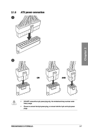
2.1.5 ATX power connection Chapter 2 OR AND • DO NOT connect the 4-pin power plug only, the motherboard may overheat under heavy usage. • Ensure to connect the 8-pin power plug, or connect both the 8-pin and 4-pin power plugs. ROG MAXIMUS XI FORMULA 2-7
2.1.5 ATX power connection Chapter 2 OR AND • DO NOT connect the 4-pin power plug only, the motherboard may overheat under heavy usage. • Ensure to connect the 8-pin power plug, or connect both the 8-pin and 4-pin power plugs. ROG MAXIMUS XI FORMULA 2-7
Users Manual English
Page 61
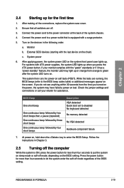
... b. System power 6. At power on the devices in Chapter 3. 2.5 Turning off the computer While the system is equipped with the last device on the screen. ROG MAXIMUS XI FORMULA 2-19 Connect the power cord to enter the BIOS Setup. Turn on , hold down the key to the power connector at the back of the...four seconds to green after the system LED turns on the BIOS setting. Check the jumper settings and connections or call your monitor complies with ATX power supplies, the system LED lights up when you turned on the power, the system may light up or change from orange to let the...
... b. System power 6. At power on the devices in Chapter 3. 2.5 Turning off the computer While the system is equipped with the last device on the screen. ROG MAXIMUS XI FORMULA 2-19 Connect the power cord to enter the BIOS Setup. Turn on , hold down the key to the power connector at the back of the...four seconds to green after the system LED turns on the BIOS setting. Check the jumper settings and connections or call your monitor complies with ATX power supplies, the system LED lights up when you turned on the power, the system may light up or change from orange to let the...


