
User Guide
Page 3
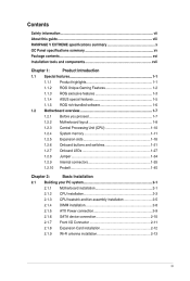
... guide viii RAMPAGE V EXTREME specifications summary OC Panel specifications summary xv Package contents xvi Installation tools and components xvii Chapter 1: Product Introduction 1.1 Special features 1-1 1.1.1 Product highlights 1-1 1.1.2 ROG Unique Gaming Features 1-2 1.1.3 ROG exclusive features 1-3 1.1.4 ASUS special features 1-5 1.1.5 ROG rich-bundled software 1-6 1.2 Motherboard overview 1-7 1.2.1 Before you proceed 1-7 1.2.2 Motherboard layout 1-8 1.2.3 Central Processing Unit (CPU) 1-10 1.2.4 System memory...
... guide viii RAMPAGE V EXTREME specifications summary OC Panel specifications summary xv Package contents xvi Installation tools and components xvii Chapter 1: Product Introduction 1.1 Special features 1-1 1.1.1 Product highlights 1-1 1.1.2 ROG Unique Gaming Features 1-2 1.1.3 ROG exclusive features 1-3 1.1.4 ASUS special features 1-5 1.1.5 ROG rich-bundled software 1-6 1.2 Motherboard overview 1-7 1.2.1 Before you proceed 1-7 1.2.2 Motherboard layout 1-8 1.2.3 Central Processing Unit (CPU) 1-10 1.2.4 System memory...
User Guide
Page 4
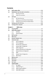
... setup 3.1 Knowing BIOS 3-1 3.2 BIOS setup program 3-2 3.2.1 EZ Mode 3-3 3.2.2 Advanced Mode 3-4 3.3 My Favorites 3-6 3.4 Main menu 3-7 3.5 Extreme Tweaker menu 3-9 3.6 Advanced menu 3-28 3.6.1 CPU Configuration 3-29 3.6.2 PCH Configuration 3-32 3.6.3 PCH Storage Configuration 3-33 3.6.4 System Agent Configuration 3-35...42 3.6.10 ROG Effects 3-42 3.7 Monitor menu 3-43 3.8 Boot menu 3-47 3.9 Tool menu 3-53 3.10 Exit menu 3-55 3.11 Updating BIOS 3-56 3.11.1 EZ Update 3-56 3.11.2 ASUS EZ Flash 2 3-57 3.11.3 ASUS CrashFree BIOS 3 3-58 3.11.4 ASUS BIOS ...
... setup 3.1 Knowing BIOS 3-1 3.2 BIOS setup program 3-2 3.2.1 EZ Mode 3-3 3.2.2 Advanced Mode 3-4 3.3 My Favorites 3-6 3.4 Main menu 3-7 3.5 Extreme Tweaker menu 3-9 3.6 Advanced menu 3-28 3.6.1 CPU Configuration 3-29 3.6.2 PCH Configuration 3-32 3.6.3 PCH Storage Configuration 3-33 3.6.4 System Agent Configuration 3-35...42 3.6.10 ROG Effects 3-42 3.7 Monitor menu 3-43 3.8 Boot menu 3-47 3.9 Tool menu 3-53 3.10 Exit menu 3-55 3.11 Updating BIOS 3-56 3.11.1 EZ Update 3-56 3.11.2 ASUS EZ Flash 2 3-57 3.11.3 ASUS CrashFree BIOS 3 3-58 3.11.4 ASUS BIOS ...
User Guide
Page 5
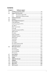
... Streamer 4.6 ROG Audio features Sonic Studio Sonic SenseAmp Sonic SoundStage DTS Connect 4.7 Sonic Radar II 4.8 GameFirst III 4.9 KeyBot 4.10 ASUS Disk Unlocker 4.11 RAMDisk 4.12 MemTweakIt 4.13 ROG CPU-Z 4.14 ROG Connect 4-1 4-1 4-1 4-3 4-4 4-4 4-7 4-7 4-8 4-10 4-11 4-13 4-14 4-17 4-18 4-19 4-21 4-22 4-23 4-26 4-27 4-29 4-39 4-41 4-41 4-43 4-45 4-46 4-47 4-49...
... Streamer 4.6 ROG Audio features Sonic Studio Sonic SenseAmp Sonic SoundStage DTS Connect 4.7 Sonic Radar II 4.8 GameFirst III 4.9 KeyBot 4.10 ASUS Disk Unlocker 4.11 RAMDisk 4.12 MemTweakIt 4.13 ROG CPU-Z 4.14 ROG Connect 4-1 4-1 4-1 4-3 4-4 4-4 4-7 4-7 4-8 4-10 4-11 4-13 4-14 4-17 4-18 4-19 4-21 4-22 4-23 4-26 4-27 4-29 4-39 4-41 4-41 4-43 4-45 4-46 4-47 4-49...
User Guide
Page 10
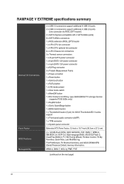
... SATAEXPRESS_E1 will be enabled. **The PCIE_X4_1 (gray) slot shares bandwidth with the PCIE_X1_1 slot, USB3_E910 and SATAExpress_E1 connector. RAMPAGE V EXTREME specifications summary emory Expansion Slots Multi-GPU Technology Storage New Inter Core, i7 Processors on LGA 2011-v3 socket Supports 22nm.../x8/x8 mode with 40-Lane CPU; supports x16, x16/x8, or x8/ x8/x8 with the M.2 connector. Intel° X99 Express Chipset with RAID 0, 1, 5, 10, and Intel Rapid Storage Technology 13 support: - 1 x SATA Express port (red@bottom, compatible with 2 x SATA 6.0 Gb/s ports) - 1 x M.2 Socket 3 with...
... SATAEXPRESS_E1 will be enabled. **The PCIE_X4_1 (gray) slot shares bandwidth with the PCIE_X1_1 slot, USB3_E910 and SATAExpress_E1 connector. RAMPAGE V EXTREME specifications summary emory Expansion Slots Multi-GPU Technology Storage New Inter Core, i7 Processors on LGA 2011-v3 socket Supports 22nm.../x8/x8 mode with 40-Lane CPU; supports x16, x16/x8, or x8/ x8/x8 with the M.2 connector. Intel° X99 Express Chipset with RAID 0, 1, 5, 10, and Intel Rapid Storage Technology 13 support: - 1 x SATA Express port (red@bottom, compatible with 2 x SATA 6.0 Gb/s ports) - 1 x M.2 Socket 3 with...

User Guide
Page 11
... audio capacitors - Sonic Studio - Content Protection for ROG Connect) 10 x USB 3.0 ports [blue] 1 x Anti-surge LAN (RJ45) port 1 x ASUS Wi-Fi GO! DTS Connect Intel° X99 Express Chipset - RAMPAGE V EXTREME specifications summary Wireless / Bluetooth SupremeFX High Definition Audio USB Back Panel...8-Channel High Definition Audio CODEC - SupremeFX Shielding Technology - Jack-detection, Multi-streaming, and Front Panel Jack-retasking - Sonic SenseAmp - supports Asus USB 3.0 Boost: - 4 x USB 3.0 ports ( at mid-board [red])* - 6 x USB 2.0 ports (2 ports at back panel, 4 ports ...
... audio capacitors - Sonic Studio - Content Protection for ROG Connect) 10 x USB 3.0 ports [blue] 1 x Anti-surge LAN (RJ45) port 1 x ASUS Wi-Fi GO! DTS Connect Intel° X99 Express Chipset - RAMPAGE V EXTREME specifications summary Wireless / Bluetooth SupremeFX High Definition Audio USB Back Panel...8-Channel High Definition Audio CODEC - SupremeFX Shielding Technology - Jack-detection, Multi-streaming, and Front Panel Jack-retasking - Sonic SenseAmp - supports Asus USB 3.0 Boost: - 4 x USB 3.0 ports ( at mid-board [red])* - 6 x USB 2.0 ports (2 ports at back panel, 4 ports ...
User Guide
Page 12
...(continued on button 1 x Reset button 1 x Safe boot button 1 x ReTry button 1 x LN2 mode jumper 1 x Slow mode switch 1 x MemOK! RAMPAGE V EXTREME specifications summary Internal I/O Connectors Form Factor BIOS Features Manageability 2 x USB 3.0 connectors support additional 4 USB 3.0 ports 2 x USB 2.0 connectors support additional 4 USB... x System panel connector Extended ATX Form Factor, 12-inch x 10.7-inch (30.5cm x 27.2 cm) 2 x 128 Mb Flash ROM, UEFI AMI BIOS, PnP, DMI2.7, WfM2.0, SM BIOS 2.8, ACPI 5.0, Multi-language BIOS, ASUS EZ Flash 2, CrashFree BIOS 3, Fl1 EZ Tuning Wizard, F6 Qfan...
...(continued on button 1 x Reset button 1 x Safe boot button 1 x ReTry button 1 x LN2 mode jumper 1 x Slow mode switch 1 x MemOK! RAMPAGE V EXTREME specifications summary Internal I/O Connectors Form Factor BIOS Features Manageability 2 x USB 3.0 connectors support additional 4 USB 3.0 ports 2 x USB 2.0 connectors support additional 4 USB... x System panel connector Extended ATX Form Factor, 12-inch x 10.7-inch (30.5cm x 27.2 cm) 2 x 128 Mb Flash ROM, UEFI AMI BIOS, PnP, DMI2.7, WfM2.0, SM BIOS 2.8, ACPI 5.0, Multi-language BIOS, ASUS EZ Flash 2, CrashFree BIOS 3, Fl1 EZ Tuning Wizard, F6 Qfan...
User Guide
Page 19
...maximum of 32Gb/s, double the 16Gb/s of 3D graphics, multimedia, and Internet applications. Functions are available when using PCie 3.0-compliant devices. ASUS RAMPAGE V EXTREME 1-1 Intel® X99 Express Chipset Intel® X99 Express Chipset is the perfect choice for a system drive making your system to ...package. PCIe 3.0 provides you the ultimate gaming experience. SATA Express support SATA Express provides faster data transfer speeds of up to 10 Gb/s allowing your OS and apps launch as fast as possible. It provides great graphics and system performance with the speed ...
...maximum of 32Gb/s, double the 16Gb/s of 3D graphics, multimedia, and Internet applications. Functions are available when using PCie 3.0-compliant devices. ASUS RAMPAGE V EXTREME 1-1 Intel® X99 Express Chipset Intel® X99 Express Chipset is the perfect choice for a system drive making your system to ...package. PCIe 3.0 provides you the ultimate gaming experience. SATA Express support SATA Express provides faster data transfer speeds of up to 10 Gb/s allowing your OS and apps launch as fast as possible. It provides great graphics and system performance with the speed ...
User Guide
Page 27
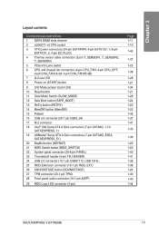
... AAFP) 29 ROG Logo LED connector (3-pin) Page 1-11 1-10 1-42 1-37 1-25 1-38 1-28 1-21 1-34 1-21 1-26 1-24 1-23 1-22 1-45 1-37 1-41 1-35 1-36 1-25 1-23 1-43 1-41 1-38 1-36 1-24 1-40 1-40 1-44 ASUS RAMPAGE V EXTREME 1-9 Layout contents Connectors/Jumpers/Slots 1 DDR4 DIMM slots channel 2 LGA2011-...(4-pin CPU_FAN; 4-pin CPU_OPT; 4-pin CHA_FAN1A-3A; 4-pin CHA_FAN1B-3B) 7 Q-Code LED 8 Power-on (START) button 9 LN2 Mode jumper (3-pin LN2) 10 Reset button 11 Slow Mode Switch (SLOW_MODE) 12 Safe Boot button (SAFE_BOOT) 13 ReTry button (RETRY) 14 MemOK! SATAEXPRESS_1) 19 ASMedia® Serial ATA 6 Gb...
... AAFP) 29 ROG Logo LED connector (3-pin) Page 1-11 1-10 1-42 1-37 1-25 1-38 1-28 1-21 1-34 1-21 1-26 1-24 1-23 1-22 1-45 1-37 1-41 1-35 1-36 1-25 1-23 1-43 1-41 1-38 1-36 1-24 1-40 1-40 1-44 ASUS RAMPAGE V EXTREME 1-9 Layout contents Connectors/Jumpers/Slots 1 DDR4 DIMM slots channel 2 LGA2011-...(4-pin CPU_FAN; 4-pin CPU_OPT; 4-pin CHA_FAN1A-3A; 4-pin CHA_FAN1B-3B) 7 Q-Code LED 8 Power-on (START) button 9 LN2 Mode jumper (3-pin LN2) 10 Reset button 11 Slow Mode Switch (SLOW_MODE) 12 Safe Boot button (SAFE_BOOT) 13 ReTry button (RETRY) 14 MemOK! SATAEXPRESS_1) 19 ASMedia® Serial ATA 6 Gb...
User Guide
Page 28
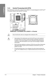
.../incorrect removal of repair only if the damage is shipment/ transit-related. • Keep the cap after installing the motherboard. ASUS will process Return Merchandise Authorization (RMA) requests only if the motherboard comes with a surface mount LGA2011-v3 socket designed for Intel...r-F i7 Processor Family for the LGA 2011-v3 socket. ASUS will shoulder the cost of the PnP cap. 1-10 Chapter 1: Product introduction RD '1::1:1' 0 AMC I=C 0 w I 'DO L ED uu Eno LEEEEnfo°591M__ImmEmEol =not RAMPAGE V EXTREME CPU LGA2011-v3 Socket Ensure that all power cables are not...
.../incorrect removal of repair only if the damage is shipment/ transit-related. • Keep the cap after installing the motherboard. ASUS will process Return Merchandise Authorization (RMA) requests only if the motherboard comes with a surface mount LGA2011-v3 socket designed for Intel...r-F i7 Processor Family for the LGA 2011-v3 socket. ASUS will shoulder the cost of the PnP cap. 1-10 Chapter 1: Product introduction RD '1::1:1' 0 AMC I=C 0 w I 'DO L ED uu Eno LEEEEnfo°591M__ImmEmEol =not RAMPAGE V EXTREME CPU LGA2011-v3 Socket Ensure that all power cables are not...
User Guide
Page 40
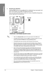
... During the tuning process, the system loads and tests failsafe memory settings. It takes about 5-10 seconds. • If your system fails to boot up when the DIMM is tested. To ... recommended in the Memory QVL (Qualified Vendors Lists) in this user manual or at www.asus.com. • If you download and update to memory tuning requirement, the system automatically reboots... properly installed. via IzQ , Eun MOW% V EXITIEWIZC Da ito ,I nami:o=olia=mrarommo anatook, RAMPAGE V EXTREME MemOK! button to boot after the tuning process is the DRAM_LED lighting continuously. A message will appear...
... During the tuning process, the system loads and tests failsafe memory settings. It takes about 5-10 seconds. • If your system fails to boot up when the DIMM is tested. To ... recommended in the Memory QVL (Qualified Vendors Lists) in this user manual or at www.asus.com. • If you download and update to memory tuning requirement, the system automatically reboots... properly installed. via IzQ , Eun MOW% V EXITIEWIZC Da ito ,I nami:o=olia=mrarommo anatook, RAMPAGE V EXTREME MemOK! button to boot after the tuning process is the DRAM_LED lighting continuously. A message will appear...

User Guide
Page 44
...does not warm fast enough, it comes out of crashes, even when trying to maintain stability at their highest frequency. 10. Temperatures that fall outside this , simply flip the switch over to Slow-Mode during critical moments when Temperature/Max Frequency... frequencies, the CPU's temperature tolerance increases. SLOW_MODE Disabled Enabled 7 (Default) I I❑O E L E =02l= 1=1=7= MEM EMEZOt RAMPAGE V EXTREME Slow Mode switch 1-26 Chapter 1: Product introduction Once it may yield instability. It will however remain stable at lower frequencies at cold temperatures.
...does not warm fast enough, it comes out of crashes, even when trying to maintain stability at their highest frequency. 10. Temperatures that fall outside this , simply flip the switch over to Slow-Mode during critical moments when Temperature/Max Frequency... frequencies, the CPU's temperature tolerance increases. SLOW_MODE Disabled Enabled 7 (Default) I I❑O E L E =02l= 1=1=7= MEM EMEZOt RAMPAGE V EXTREME Slow Mode switch 1-26 Chapter 1: Product introduction Once it may yield instability. It will however remain stable at lower frequencies at cold temperatures.
User Guide
Page 47
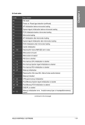
... microcode loading OB Cache initialization OC - IQ 00 Not used .0 U 01 Power on the next page) ASUS RAMPAGE V EXTREME 1-29 OD Reserved for future AMI SEC error codes OE Microcode not found OF Microcode not loaded 10 PEI Core is started 11 -14 Pre-memory CPU initialization is started 15 -18 Pre-memory System...
... microcode loading OB Cache initialization OC - IQ 00 Not used .0 U 01 Power on the next page) ASUS RAMPAGE V EXTREME 1-29 OD Reserved for future AMI SEC error codes OE Microcode not found OF Microcode not loaded 10 PEI Core is started 11 -14 Pre-memory CPU initialization is started 15 -18 Pre-memory System...
User Guide
Page 53
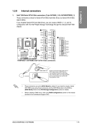
...creating a RAID array, refer to the RAID configurations section or the manual bundled in the BIOS to SATA device. ASUS RAMPAGE V EXTREME 1-35 SATA6G_4 1.0.17,TXPO IISATA_TGXNln4 GSATAJO044 RSATAJO:Pa SATA6G_7 SATA6G_6 o AKIO' OND GSATA_TXP7 IISATA_TXN) GND FISATAJUOG O FI...Ert =mot OM FISATA_MS RSATA_TXNII OND IISATAJIXN0 PAGIAJGO29 OND OND FISATA_TXPIO IISMA_TXN10 GND PSATUTOGO GSATAPX1.10 OND - Intel® X99 Serial ATA 6 Gb/s connectors (7-pin SATA6G_1-10; 1.2.9 Internal connectors 1. SATAEXPRESS_1) These connectors connect to avoid mechanical conflict with the ...
...creating a RAID array, refer to the RAID configurations section or the manual bundled in the BIOS to SATA device. ASUS RAMPAGE V EXTREME 1-35 SATA6G_4 1.0.17,TXPO IISATA_TGXNln4 GSATAJO044 RSATAJO:Pa SATA6G_7 SATA6G_6 o AKIO' OND GSATA_TXP7 IISATA_TXN) GND FISATAJUOG O FI...Ert =mot OM FISATA_MS RSATA_TXNII OND IISATAJIXN0 PAGIAJGO29 OND OND FISATA_TXPIO IISMA_TXN10 GND PSATUTOGO GSATAPX1.10 OND - Intel® X99 Serial ATA 6 Gb/s connectors (7-pin SATA6G_1-10; 1.2.9 Internal connectors 1. SATAEXPRESS_1) These connectors connect to avoid mechanical conflict with the ...
User Guide
Page 56
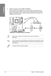
USB1314) r-F These connectors are for USB 2.0 ports. Ptg RAMPAGE V EXTREME USB2.0 connectors zo OUSB1112 PIN 1 Never connect a 1394 cable to 480 Mbps connection speed. 1E= 0 f= 0 0 /NM O ,c) Lu Er OUSB1314 PIN 1 - 1 - 1 . The USB 2.0 module is purchased ... the module to the USB connector onboard if your chassis supports front panel USB ports. You can connect the front panel USB cable to the ASUS Q-Connector (USB) first, and then install the Q-Connector (USB) to a slot opening at the back of the system chassis. USB 2.0 connectors...
USB1314) r-F These connectors are for USB 2.0 ports. Ptg RAMPAGE V EXTREME USB2.0 connectors zo OUSB1112 PIN 1 Never connect a 1394 cable to 480 Mbps connection speed. 1E= 0 f= 0 0 /NM O ,c) Lu Er OUSB1314 PIN 1 - 1 - 1 . The USB 2.0 module is purchased ... the module to the USB connector onboard if your chassis supports front panel USB ports. You can connect the front panel USB cable to the ASUS Q-Connector (USB) first, and then install the Q-Connector (USB) to a slot opening at the back of the system chassis. USB 2.0 connectors...
User Guide
Page 58
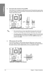
CI AIM AAFP PIN 9 $22 2 222.2 z HD-audio-compliant Legacy AC'97 pin definition compliant definition RAMPAGE V EXTREME Analog front panel connector • We recommend that supports either HD Audio or legacy AC'97 audio standard. By default, this ...set to [HD]; E u MP= u CJ • • • Eg c2H,A, TPM zcls:Lk, (z73e:5 ,.Zz m •=• RAMPAGE V EXTREME TPM connector 1-40 Chapter 1: Product introduction 8. Front panel audio connector (10-1 pin AAFP) This connector is set the Front Panel Type item in the BIOS setup to [HD]. 9. TPM connector (20...
CI AIM AAFP PIN 9 $22 2 222.2 z HD-audio-compliant Legacy AC'97 pin definition compliant definition RAMPAGE V EXTREME Analog front panel connector • We recommend that supports either HD Audio or legacy AC'97 audio standard. By default, this ...set to [HD]; E u MP= u CJ • • • Eg c2H,A, TPM zcls:Lk, (z73e:5 ,.Zz m •=• RAMPAGE V EXTREME TPM connector 1-40 Chapter 1: Product introduction 8. Front panel audio connector (10-1 pin AAFP) This connector is set the Front Panel Type item in the BIOS setup to [HD]. 9. TPM connector (20...

User Guide
Page 59
ASUS RAMPAGE V EXTREME 1-41 When PCIE_X8_4 is for the add-on Thunderbolt I/O card that supports Intel's Thunderbolt a Technology, allowing you to connect up to six Thunderbolt-enabled devices and a CU DisplayPort-enabled display in a daisy-chain configuration. 10. U CI= 'Nur J TB_HEADER H -7177 21111 Izo ID() LE 1=10. 11 EE =t === mmozd RAMPAGE V EXTREME TB_HEADER connector 11. Thunderbolt header (5-pin...
ASUS RAMPAGE V EXTREME 1-41 When PCIE_X8_4 is for the add-on Thunderbolt I/O card that supports Intel's Thunderbolt a Technology, allowing you to connect up to six Thunderbolt-enabled devices and a CU DisplayPort-enabled display in a daisy-chain configuration. 10. U CI= 'Nur J TB_HEADER H -7177 21111 Izo ID() LE 1=10. 11 EE =t === mmozd RAMPAGE V EXTREME TB_HEADER connector 11. Thunderbolt header (5-pin...

User Guide
Page 63
1.2.10 Probelt The ROG Probelt allows you to the motherboard as shown on the following figure. 0 CD 0 00 The illustration above are for reference only, the ... the respective Probelt points. .0 U El= T u GND O VIN El CORE El CACHE * SA ▪ RAM_AB ▪ RAM_CD ▪ PCH ▪ PCHJO un u RAMPAGE V EXTREME Probelt Using Probelt You can connect the multimeter to detect your system's current voltage and OC settings. Use a co multimeter to measure the Probelt points even during overclocking. ASUS RAMPAGE V EXTREME 1-45
1.2.10 Probelt The ROG Probelt allows you to the motherboard as shown on the following figure. 0 CD 0 00 The illustration above are for reference only, the ... the respective Probelt points. .0 U El= T u GND O VIN El CORE El CACHE * SA ▪ RAM_AB ▪ RAM_CD ▪ PCH ▪ PCHJO un u RAMPAGE V EXTREME Probelt Using Probelt You can connect the multimeter to detect your system's current voltage and OC settings. Use a co multimeter to measure the Probelt points even during overclocking. ASUS RAMPAGE V EXTREME 1-45
User Guide
Page 65
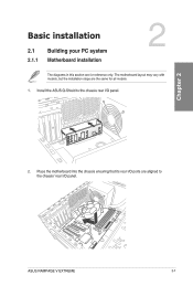
Install the ASUS Q-Shield to the chassis' rear I /O panel. a 10 U o k7a0o0g700,o0,og,,00,00g40no0olLi60oOo000i0. Basic installation 2.1 2.1.1 Building your PC system Motherboard installation The diagrams in this section are for all models. +CaT, 1. Place the motherboard into the chassis ensuring that its rear I/O ports are the same for reference only. ASUS RAMPAGE V EXTREME 2-1 The motherboard layout may vary with N models, but the installation steps are aligned to the chassis rear I /O panel. tosogsosoossso9, c oo 8 a CD 2.
Install the ASUS Q-Shield to the chassis' rear I /O panel. a 10 U o k7a0o0g700,o0,og,,00,00g40no0olLi60oOo000i0. Basic installation 2.1 2.1.1 Building your PC system Motherboard installation The diagrams in this section are for all models. +CaT, 1. Place the motherboard into the chassis ensuring that its rear I/O ports are the same for reference only. ASUS RAMPAGE V EXTREME 2-1 The motherboard layout may vary with N models, but the installation steps are aligned to the chassis rear I /O panel. tosogsosoossso9, c oo 8 a CD 2.

User Guide
Page 67
2.1.2 CPU installation Ensure that you install the correct CPU designed for LGA1150, LGA1155, and LGA1156 sockets on the LGA2011-v3 socket. 0 0 O O 0 O O N O 0 Triangle mark CT, a 10 U 0 0 0 air Load lever B 10 O O O O 0 O O O O 0 O O O O ASUS RAMPAGE V EXTREME 2-3 DO NOT install a CPU designed for LGA2011-v3 socket only.
2.1.2 CPU installation Ensure that you install the correct CPU designed for LGA1150, LGA1155, and LGA1156 sockets on the LGA2011-v3 socket. 0 0 O O 0 O O N O 0 Triangle mark CT, a 10 U 0 0 0 air Load lever B 10 O O O O 0 O O O O 0 O O O O ASUS RAMPAGE V EXTREME 2-3 DO NOT install a CPU designed for LGA2011-v3 socket only.

User Guide
Page 73
2.1.5 0 ATX Power connection 0 N +CaT, a 10 = U OR II1YTI I I OR ...> .... ASUS RAMPAGE V EXTREME 2-9
2.1.5 0 ATX Power connection 0 N +CaT, a 10 = U OR II1YTI I I OR ...> .... ASUS RAMPAGE V EXTREME 2-9


