
User Manual
Page 4
... 2.11.2 Using the dual function power switch 2-54 Chapter 3: BIOS setup 3.1 Managing and updating your BIOS 3-1 3.1.1 ASUS Update utility 3-1 3.1.2 ASUS EZ Flash 2 utility 3-4 3.1.3 ASUS CrashFree BIOS 3 utility 3-5 3.2 BIOS setup program 3-6 3.2.1 BIOS menu screen 3-7 3.2.2 Menu bar 3-7 3.2.3 Navigation keys 3-7 3.2.4 Menu items 3-8 3.2.5 Submenu items 3-8 3.2.6 Configuration fields 3-8 3.2.7 Pop-up window 3-8 3.2.8 Scroll bar 3-8 3.2.9 General help 3-8 3.3 Extreme Tweaker menu 3-9 3.3.1 CPU Level Up [Auto 3-10 3.3.2 Sync...
... 2.11.2 Using the dual function power switch 2-54 Chapter 3: BIOS setup 3.1 Managing and updating your BIOS 3-1 3.1.1 ASUS Update utility 3-1 3.1.2 ASUS EZ Flash 2 utility 3-4 3.1.3 ASUS CrashFree BIOS 3 utility 3-5 3.2 BIOS setup program 3-6 3.2.1 BIOS menu screen 3-7 3.2.2 Menu bar 3-7 3.2.3 Navigation keys 3-7 3.2.4 Menu items 3-8 3.2.5 Submenu items 3-8 3.2.6 Configuration fields 3-8 3.2.7 Pop-up window 3-8 3.2.8 Scroll bar 3-8 3.2.9 General help 3-8 3.3 Extreme Tweaker menu 3-9 3.3.1 CPU Level Up [Auto 3-10 3.3.2 Sync...

User Manual
Page 6
... [Disabled 3-34 3.6.7 Hardware Monitor 3-36 3.7 Boot menu 3-39 3.7.1 Boot Device Priority 3-39 3.7.2 Boot Settings Configuration 3-40 3.7.3 Security 3-41 3.8 Tools menu 3-43 3.8.1 ASUS EZ Flash 2 3-43 3.8.2 ASUS O.C. Profile 3-44 3.8.3 GO_Button File 3-46 3.8.4 BIOS FlashBack 3-47 3.9 Exit menu 3-48 Chapter 4: Software support 4.1 Installing an operating system 4-1 4.2 Support DVD information 4-1 4.2.1 Running the support DVD 4-1 4.2.2 Drivers menu...
... [Disabled 3-34 3.6.7 Hardware Monitor 3-36 3.7 Boot menu 3-39 3.7.1 Boot Device Priority 3-39 3.7.2 Boot Settings Configuration 3-40 3.7.3 Security 3-41 3.8 Tools menu 3-43 3.8.1 ASUS EZ Flash 2 3-43 3.8.2 ASUS O.C. Profile 3-44 3.8.3 GO_Button File 3-46 3.8.4 BIOS FlashBack 3-47 3.9 Exit menu 3-48 Chapter 4: Software support 4.1 Installing an operating system 4-1 4.2 Support DVD information 4-1 4.2.1 Running the support DVD 4-1 4.2.2 Drivers menu...

User Manual
Page 7
...Manager 4-9 4.3.2 ASUS PC Probe II 4-15 4.3.3 ASUS AI Suite 4-21 4.3.4 ASUS Fan Xpert 4-23 4.3.5 CPU Level Up 4-24 4.3.6 TurboV EVO 4-24 4.3.7 ROG Connect 4-26 4.4 RAID configurations 4-28 4.4.1 RAID definitions 4-28 4.4.2 Installing Serial ATA hard disks 4-29 4.4.3 Setting the RAID item in BIOS 4-29 4.4.4...® SLI™ technology 5-6 Appendix: Reference information A.1 Debug code table A-1 A.2 Qualified Vendors Lists (QVL) for BIOS FlashBack A-4 A.3 Qualified Vendors Lists (QVL) for RC Bluetooth A-4 A.4 Qualified Vendors Lists (QVL) for 500W Power Supply or above A-5 vii
...Manager 4-9 4.3.2 ASUS PC Probe II 4-15 4.3.3 ASUS AI Suite 4-21 4.3.4 ASUS Fan Xpert 4-23 4.3.5 CPU Level Up 4-24 4.3.6 TurboV EVO 4-24 4.3.7 ROG Connect 4-26 4.4 RAID configurations 4-28 4.4.1 RAID definitions 4-28 4.4.2 Installing Serial ATA hard disks 4-29 4.4.3 Setting the RAID item in BIOS 4-29 4.4.4...® SLI™ technology 5-6 Appendix: Reference information A.1 Debug code table A-1 A.2 Qualified Vendors Lists (QVL) for BIOS FlashBack A-4 A.3 Qualified Vendors Lists (QVL) for RC Bluetooth A-4 A.4 Qualified Vendors Lists (QVL) for 500W Power Supply or above A-5 vii

User Manual
Page 14
...procedures that you need when installing and configuring the motherboard. ASUS websites The ASUS website provides updated information on the motherboard. • Chapter 3: BIOS setup This chapter tells how to change system settings through the BIOS Setup menus. How this guide This user guide contains ... as warranty flyers, that may refer to perform when installing system components. Where to find more information Refer to the ASUS contact information. 2. These documents are also provided. • Chapter 4: Software support This chapter describes the contents of the switches, ...
...procedures that you need when installing and configuring the motherboard. ASUS websites The ASUS website provides updated information on the motherboard. • Chapter 3: BIOS setup This chapter tells how to change system settings through the BIOS Setup menus. How this guide This user guide contains ... as warranty flyers, that may refer to perform when installing system components. Where to find more information Refer to the ASUS contact information. 2. These documents are also provided. • Chapter 4: Software support This chapter describes the contents of the switches, ...
User Manual
Page 17
...;) CPU Level Up MemOK! Rampage III Extreme specifications summary USB ROG Exclusive Overclocking Features Other Special Features BIOS Features NEC® USB 3.0 controller - 2 x USB 3.0/2.0 ports (at back panel) Intel® ICH10R Southbridge - 9 x USB 2.0/1.1 ports (2 ports at midboard; 6 ports at rear) ASUS MyLogo3 ASUS Fan Xpert ASUS EZ Flash 2 ASUS CrashFree BIOS 3 Q-Fan Plus ROG BIOS Wallpaper ASUS Q-Connector ASUS Q-LED (CPU, DRAM...
...;) CPU Level Up MemOK! Rampage III Extreme specifications summary USB ROG Exclusive Overclocking Features Other Special Features BIOS Features NEC® USB 3.0 controller - 2 x USB 3.0/2.0 ports (at back panel) Intel® ICH10R Southbridge - 9 x USB 2.0/1.1 ports (2 ports at midboard; 6 ports at rear) ASUS MyLogo3 ASUS Fan Xpert ASUS EZ Flash 2 ASUS CrashFree BIOS 3 Q-Fan Plus ROG BIOS Wallpaper ASUS Q-Connector ASUS Q-LED (CPU, DRAM...

User Manual
Page 18
xviii Rampage III Extreme specifications summary Manageability Back Panel I/O Ports Internal I/O Connectors Software Form... 2 x EZ Plug connectors (4-pin Molex Power connectors) 1 x OC Station header 1 x RC Bluetooth header 1 x Go Button 1 x BIOS Switch button 1 x ROG light connector 1 x CD Audio in 1 x Audio front panel 1 x System panel connector Support DVD: - Drivers... and Applications Futuremark® 3DMark® Vantage Advanced Edition Kaspersky Anti-Virus ASUS TurboV EVO Utility ASUS PC Probe II ASUS Update ASUS AI Suite extended ATX Form Factor, 12"x 10.6" (30.5cm x 26.9cm)...
xviii Rampage III Extreme specifications summary Manageability Back Panel I/O Ports Internal I/O Connectors Software Form... 2 x EZ Plug connectors (4-pin Molex Power connectors) 1 x OC Station header 1 x RC Bluetooth header 1 x Go Button 1 x BIOS Switch button 1 x ROG light connector 1 x CD Audio in 1 x Audio front panel 1 x System panel connector Support DVD: - Drivers... and Applications Futuremark® 3DMark® Vantage Advanced Edition Kaspersky Anti-Virus ASUS TurboV EVO Utility ASUS PC Probe II ASUS Update ASUS AI Suite extended ATX Form Factor, 12"x 10.6" (30.5cm x 26.9cm)...

User Manual
Page 23
...architecture double the bandwidth of the latest operation system, 3D graphics, multimedia, and Internet applications. ROG Connect Plug and Overclock - ROG Rampage III Extreme 1-3 Refer to do! PCIe 2.0 Double Speed; When users want to use oridinary bluetooth functions, just simply push the button once ...as well as voltages and frequency on -the-fly parameter adjustments at a purely hardware level. Diagram, power, reset button, flash BIOS through a USB cable, allowing you the whole new idea of conventional overclocking Still overclocking in real-time via a notebook-just like ...
...architecture double the bandwidth of the latest operation system, 3D graphics, multimedia, and Internet applications. ROG Connect Plug and Overclock - ROG Rampage III Extreme 1-3 Refer to do! PCIe 2.0 Double Speed; When users want to use oridinary bluetooth functions, just simply push the button once ...as well as voltages and frequency on -the-fly parameter adjustments at a purely hardware level. Diagram, power, reset button, flash BIOS through a USB cable, allowing you the whole new idea of conventional overclocking Still overclocking in real-time via a notebook-just like ...

User Manual
Page 24
.... 1-4 Chapter 1: Product Introduction Any memory is the fastest memory booting solution today. Extreme Engine Digi+ Powerful combination of the motherboard at any stage! Worry no doubt that easy USB BIOS Flashback must be the most convenient way to determine failsafe settings that gives users full disposal... hardware level. Refer to page 2-32 for PC enthusiasts and it comes to bring the ultimate user experience. Extreme Engine Digi+ balances the need to enter the BIOS or the operating system, just plug the thumb drive into the ROG Connect port & push the ROG Connect button...
.... 1-4 Chapter 1: Product Introduction Any memory is the fastest memory booting solution today. Extreme Engine Digi+ Powerful combination of the motherboard at any stage! Worry no doubt that easy USB BIOS Flashback must be the most convenient way to determine failsafe settings that gives users full disposal... hardware level. Refer to page 2-32 for PC enthusiasts and it comes to bring the ultimate user experience. Extreme Engine Digi+ balances the need to enter the BIOS or the operating system, just plug the thumb drive into the ROG Connect port & push the ROG Connect button...

User Manual
Page 25
...the overclocking adventure, while the other BIOS is never as easy as the "red zone" of extreme performance, overvoltage adjustment is answered! Extreme Tweaker One stop shop to save & boot from. With the new BIOS Flashback, PC enthusiasts can be stored ...the "SaveGame" function, one stop performance tuning shop Extreme Tweakers is the one BIOS can overclock with hardware-based overclocking ProbeIt takes the guesswork out of locating the motherboard's measurement points, identifying them clearly in a intuitive color-coded fashion. ROG Rampage III Extreme 1-5
...the overclocking adventure, while the other BIOS is never as easy as the "red zone" of extreme performance, overvoltage adjustment is answered! Extreme Tweaker One stop shop to save & boot from. With the new BIOS Flashback, PC enthusiasts can be stored ...the "SaveGame" function, one stop performance tuning shop Extreme Tweakers is the one BIOS can overclock with hardware-based overclocking ProbeIt takes the guesswork out of locating the motherboard's measurement points, identifying them clearly in a intuitive color-coded fashion. ROG Rampage III Extreme 1-5
User Manual
Page 27
...0Gb/s data transfer rates. Profile Conveniently store or load multiple BIOS settings Freely share and distribute favorite overclocking settings The motherboard features the ASUS O.C. SATA 6Gb/s Support Experience the Future of current bus systems.... O.C. It is renowned for malicious program detection rates that are among the industry's highest. Supporting next-generation Serial ATA (SATA) storage interface, this motherboard delivers up to conveniently store or load multiple BIOS settings. ROG Rampage III Extreme...
...0Gb/s data transfer rates. Profile Conveniently store or load multiple BIOS settings Freely share and distribute favorite overclocking settings The motherboard features the ASUS O.C. SATA 6Gb/s Support Experience the Future of current bus systems.... O.C. It is renowned for malicious program detection rates that are among the industry's highest. Supporting next-generation Serial ATA (SATA) storage interface, this motherboard delivers up to conveniently store or load multiple BIOS settings. ROG Rampage III Extreme...

User Manual
Page 32
... the location of the northbridge/ southbridge LEDs and the table below for LED definition. 2. You may adjust the voltages in BIOS. Refer to display in BIOS. For more information about voltage adjustment, refer to the illustration below for the location of the memory LED and the table ... an onboard switch for LED definition. 3. The northbridge LED displays either the 1.50V CPU PLL voltage or the 1.05V SB voltage. Refer to 3.3 Extreme Tweaker menu. 1. CPU LED The CPU LED has three voltage displays: CPU Voltage, CPU PLL, and IMC Voltage; Onboard LEDs The motherboard comes with...
... the location of the northbridge/ southbridge LEDs and the table below for LED definition. 2. You may adjust the voltages in BIOS. Refer to display in BIOS. For more information about voltage adjustment, refer to the illustration below for the location of the memory LED and the table ... an onboard switch for LED definition. 3. The northbridge LED displays either the 1.50V CPU PLL voltage or the 1.05V SB voltage. Refer to 3.3 Extreme Tweaker menu. 1. CPU LED The CPU LED has three voltage displays: CPU Voltage, CPU PLL, and IMC Voltage; Onboard LEDs The motherboard comes with...

User Manual
Page 34
GO LED Blinking: Indicates that the system loads the preset profile (GO_Button file) for temporary overclocking when in use. 6. Press the BIOS button to switch between BIOS1 and BIOS2 and the LED lights up when the corresponding BIOS is enabled before POST. is in OS. 2-4 Chapter 2: Hardware information Lighting: Indicates that MemOK! BIOS LED The BIOS LEDs help indicate the BIOS activity. 5.
GO LED Blinking: Indicates that the system loads the preset profile (GO_Button file) for temporary overclocking when in use. 6. Press the BIOS button to switch between BIOS1 and BIOS2 and the LED lights up when the corresponding BIOS is enabled before POST. is in OS. 2-4 Chapter 2: Hardware information Lighting: Indicates that MemOK! BIOS LED The BIOS LEDs help indicate the BIOS activity. 5.

User Manual
Page 37
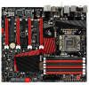
DDR3 DIMM slots 7. PCIe x16 Lane switch 11. ICH10R Serial ATA connectors (7-pin SATA 1-6 [grey]) 14. ROG Rampage III Extreme 2-7 2.2.2 Layout contents Connectors/Jumpers/Switches/Slots 1. CPU, chassis, and optional fan connectors (4-pin CPU_FAN; 4-pin PWR_FAN; 4-pin CHA_FAN1-3; 4-pin OPT_FAN1-3) 3. Thermal sensor cable connectors ... (8-pin OC_STATION) 20. LN2 Mode jumper (3-pin LN2) 9. Optical drive audio connector (4-pin CD) 22. Front panel audio connector (10-1 pin AAFP) 23. BIOS switch 17. LGA1366 CPU Socket 6. Q reset button 2.
DDR3 DIMM slots 7. PCIe x16 Lane switch 11. ICH10R Serial ATA connectors (7-pin SATA 1-6 [grey]) 14. ROG Rampage III Extreme 2-7 2.2.2 Layout contents Connectors/Jumpers/Switches/Slots 1. CPU, chassis, and optional fan connectors (4-pin CPU_FAN; 4-pin PWR_FAN; 4-pin CHA_FAN1-3; 4-pin OPT_FAN1-3) 3. Thermal sensor cable connectors ... (8-pin OC_STATION) 20. LN2 Mode jumper (3-pin LN2) 9. Optical drive audio connector (4-pin CD) 22. Front panel audio connector (10-1 pin AAFP) 23. BIOS switch 17. LGA1366 CPU Socket 6. Q reset button 2.

User Manual
Page 55
...drivers support "Share IRQ" or that came with the slot and press firmly until the card is already installed in a chassis). 3. ROG Rampage III Extreme 2-25 Refer to the chassis with the screw you removed earlier. 6. Replace the system cover. 2.5.2 Configuring an expansion card After installing the... Failure to use . 4. Remove the system unit cover (if your motherboard is completely seated on the system and change the necessary BIOS settings, if any. Otherwise, conflicts will arise between the two PCI groups, making the system unstable and the card inoperable. Assign an...
...drivers support "Share IRQ" or that came with the slot and press firmly until the card is already installed in a chassis). 3. ROG Rampage III Extreme 2-25 Refer to the chassis with the screw you removed earlier. 6. Replace the system cover. 2.5.2 Configuring an expansion card After installing the... Failure to use . 4. Remove the system unit cover (if your motherboard is completely seated on the system and change the necessary BIOS settings, if any. Otherwise, conflicts will arise between the two PCI groups, making the system unstable and the card inoperable. Assign an...

User Manual
Page 59
... Recall) feature, shut down the clr CMOS switch on the back I /O helps you to default values. Press down and reboot the system so the BIOS can clear the CMOS memory and system setup parameters by erasing the CMOS RTC RAM data. You can automatically reset CPU parameter settings to enable... The clr CMOS switch will not function if the CLRTC_SW jumper is moved to the Disable position. • Ensure to re-enter your previous BIOS settings after you clear the CMOS. • You do not need to clear the RTC when the system hangs due to re-enter data. ROG Rampage III Extreme 2-29
... Recall) feature, shut down the clr CMOS switch on the back I /O helps you to default values. Press down and reboot the system so the BIOS can clear the CMOS memory and system setup parameters by erasing the CMOS RTC RAM data. You can automatically reset CPU parameter settings to enable... The clr CMOS switch will not function if the CLRTC_SW jumper is moved to the Disable position. • Ensure to re-enter your previous BIOS settings after you clear the CMOS. • You do not need to clear the RTC when the system hangs due to re-enter data. ROG Rampage III Extreme 2-29

User Manual
Page 63
... panel connectors Rear panel connectors 1. USB 3.0 ports 1 and 2 12. 6. RC Bluetooth switch 11. 5. See section 3.5.3 Onboard Devices Configuration for details. USB 2.0 ports 3 and 4 13. 7. ROG Rampage III Extreme 2-33 Optical S/PDIF Out port IEEE 1394a port External SATA port USB 2.0 ports 1 and 2 ROG Connect switch USB 2.0 port 14/ ROG Connect port Audio ports...
... panel connectors Rear panel connectors 1. USB 3.0 ports 1 and 2 12. 6. RC Bluetooth switch 11. 5. See section 3.5.3 Onboard Devices Configuration for details. USB 2.0 ports 3 and 4 13. 7. ROG Rampage III Extreme 2-33 Optical S/PDIF Out port IEEE 1394a port External SATA port USB 2.0 ports 1 and 2 ROG Connect switch USB 2.0 port 14/ ROG Connect port Audio ports...

User Manual
Page 64
... Connect cable to the ROG Connect port and the other computer through the provided ROG Connect cable.This switch also features USB BIOS FlashBack, which enables you to monitor and control remotely with standby power). 4. Connect the USB flash drive to connection. When the... Refer to the Appendix for the qualified vendor list for the USB flash disk before using the USB BIOS Flashback function. 2-34 Chapter 2: Hardware information Download the latest BIOS from ASUS support website. * LAN port LED indications Activity/Link Speed LED OFF OFF Yellow Blinking OFF Yellow Blinking...
... Connect cable to the ROG Connect port and the other computer through the provided ROG Connect cable.This switch also features USB BIOS FlashBack, which enables you to monitor and control remotely with standby power). 4. Connect the USB flash drive to connection. When the... Refer to the Appendix for the qualified vendor list for the USB flash disk before using the USB BIOS Flashback function. 2-34 Chapter 2: Hardware information Download the latest BIOS from ASUS support website. * LAN port LED indications Activity/Link Speed LED OFF OFF Yellow Blinking OFF Yellow Blinking...

User Manual
Page 69
...8226; These connectors are for the Serial ATA signal cables for details. ROG Rampage III Extreme 2-39 In Standard IDE mode, you can connect Serial ATA boot/data hard disk drives to these connectors, set the Configure SATA as in the BIOS to [AHCI]. 2.9.4 Internal connectors 1. ���IC��... using Windows® XP SP2 or later versions. • When using hot-plug and NCQ, set the Configure SATA as item in the BIOS to create a Serial ATA RAID set using Serial ATA hard disk drives. See section 3.4.5 Storage Configuration for Serial ATA hard disk drives and...
...8226; These connectors are for the Serial ATA signal cables for details. ROG Rampage III Extreme 2-39 In Standard IDE mode, you can connect Serial ATA boot/data hard disk drives to these connectors, set the Configure SATA as in the BIOS to [AHCI]. 2.9.4 Internal connectors 1. ���IC��... using Windows® XP SP2 or later versions. • When using hot-plug and NCQ, set the Configure SATA as item in the BIOS to create a Serial ATA RAID set using Serial ATA hard disk drives. See section 3.4.5 Storage Configuration for Serial ATA hard disk drives and...
User Manual
Page 70
... ATA hard disk drive or optical disc drive via Serial ATA 6.0 Gb/s signal cables. • These connectors are set the Marvell Controller item in the BIOS to section 3.5.3 Onboard Devices Configuration for details. 3. In Standard IDE mode, you can connect Serial ATA data hard disk drives to these connectors. • You...
... ATA hard disk drive or optical disc drive via Serial ATA 6.0 Gb/s signal cables. • These connectors are set the Marvell Controller item in the BIOS to section 3.5.3 Onboard Devices Configuration for details. 3. In Standard IDE mode, you can connect Serial ATA data hard disk drives to these connectors. • You...

User Manual
Page 74
Enable OPT FAN1/2/3 overheat protection in BIOS if you connect thermal sensor cables to monitor temperature. Connect the thermal sensor cables to these connectors. 11. Optical drive audio connector (4-pin CD) These ...
Enable OPT FAN1/2/3 overheat protection in BIOS if you connect thermal sensor cables to monitor temperature. Connect the thermal sensor cables to these connectors. 11. Optical drive audio connector (4-pin CD) These ...


