

User Manual
Page 4
... the computer 2-61 2.5.1 Using the OS shut down function 2-61 2.5.2 Using the dual function power switch 2-61 Chapter 3: BIOS Setup 3.1 Managing and updating your BIOS 3-1 3.1.1 ASUS Update utility 3-1 3.1.2 ASUS EZ Flash 2 utility 3-5 3.1.3 ASUS CrashFree BIOS 3 utility 3-6 3.2 BIOS Setup program 3-7 3.2.1 BIOS menu screen 3-8 3.2.2 Menu bar 3-8 3.2.3 Navigation keys 3-8 3.2.4 Menu items 3-9 3.2.5 Submenu items 3-9 3.2.6 Configuration fields 3-9 3.2.7 Pop-up window 3-9 3.2.8 Scroll bar 3-9 3.2.9 General...
... the computer 2-61 2.5.1 Using the OS shut down function 2-61 2.5.2 Using the dual function power switch 2-61 Chapter 3: BIOS Setup 3.1 Managing and updating your BIOS 3-1 3.1.1 ASUS Update utility 3-1 3.1.2 ASUS EZ Flash 2 utility 3-5 3.1.3 ASUS CrashFree BIOS 3 utility 3-6 3.2 BIOS Setup program 3-7 3.2.1 BIOS menu screen 3-8 3.2.2 Menu bar 3-8 3.2.3 Navigation keys 3-8 3.2.4 Menu items 3-9 3.2.5 Submenu items 3-9 3.2.6 Configuration fields 3-9 3.2.7 Pop-up window 3-9 3.2.8 Scroll bar 3-9 3.2.9 General...

User Manual
Page 7
... Wi-Fi Agent 4-22 4.3.11 Audio configurations 4-25 4.4 RAID configurations 4-27 4.4.1 RAID definitions 4-27 4.4.2 Installing Serial ATA hard disks 4-28 4.4.3 Setting the RAID item in BIOS 4-28 4.4.4 Intel® Rapid Storage Technology Option ROM utility..... 4-29 4.5 Creating a RAID driver disk 4-33 4.5.1 Creating a RAID driver disk without entering the OS.... 4-33 4.5.2 Creating...
... Wi-Fi Agent 4-22 4.3.11 Audio configurations 4-25 4.4 RAID configurations 4-27 4.4.1 RAID definitions 4-27 4.4.2 Installing Serial ATA hard disks 4-28 4.4.3 Setting the RAID item in BIOS 4-28 4.4.4 Intel® Rapid Storage Technology Option ROM utility..... 4-29 4.5 Creating a RAID driver disk 4-33 4.5.1 Creating a RAID driver disk without entering the OS.... 4-33 4.5.2 Creating...

User Manual
Page 15
...this guide This user guide contains the information you have been added by your dealer. ASUS websites The ASUS website provides updated information on the motherboard. • Chapter 3: BIOS setup This chapter tells how to install and configure multiple ATI® CrossFireX™ ...and NVIDIA® SLI™ graphics cards. Detailed descriptions of the BIOS parameters are not part of the switches, jumpers, and connectors on ASUS hardware and software products. It includes description of the standard package. These documents are also provided...
...this guide This user guide contains the information you have been added by your dealer. ASUS websites The ASUS website provides updated information on the motherboard. • Chapter 3: BIOS setup This chapter tells how to install and configure multiple ATI® CrossFireX™ ...and NVIDIA® SLI™ graphics cards. Detailed descriptions of the BIOS parameters are not part of the switches, jumpers, and connectors on ASUS hardware and software products. It includes description of the standard package. These documents are also provided...

User Manual
Page 19
Onboard Switches: Power / Reset / Clr CMOS (at rear) ASUS MyLogo3 ASUS Fan Xpert ASUS EZ Flash 2 ASUS CrashFree BIOS 3 Q-Fan Plus ROG BIOS Wallpaper ASUS EPU Engine ASUS Q-Connector ASUS Q-LED (CPU, DRAM, VGA, Boot Device LED) ASUS Q-Slot ASUS Q-DIMM 1 x PS/2 Keyboard port 2 x Wi-Fi antenna jacks 1 x Clr ...65533;ll�) CPU Level Up MemOK! Rampage III Black Edition specifications summary ROG Exclusive Overclocking Features Other Special Features Back Panel I/O Ports Manageability BIOS Features ProbeIt iROG Extreme Tweaker BIOS Flashback with onboard switch button Loadline Calibration ROG...
Onboard Switches: Power / Reset / Clr CMOS (at rear) ASUS MyLogo3 ASUS Fan Xpert ASUS EZ Flash 2 ASUS CrashFree BIOS 3 Q-Fan Plus ROG BIOS Wallpaper ASUS EPU Engine ASUS Q-Connector ASUS Q-LED (CPU, DRAM, VGA, Boot Device LED) ASUS Q-Slot ASUS Q-DIMM 1 x PS/2 Keyboard port 2 x Wi-Fi antenna jacks 1 x Clr ...65533;ll�) CPU Level Up MemOK! Rampage III Black Edition specifications summary ROG Exclusive Overclocking Features Other Special Features Back Panel I/O Ports Manageability BIOS Features ProbeIt iROG Extreme Tweaker BIOS Flashback with onboard switch button Loadline Calibration ROG...

User Manual
Page 20
xx Rampage III Black Edition specifications summary Internal I/O Connectors Software Form Factor 1 x USB 3.0 connector supports additional 2 USB 3.0 ��p�o�rt�s 2 x USB 2.0 connectors support additional 4 USB ... 1 x EZ Plug connector (4-pin Molex Power connector) 1 x Go Button 1 x BIOS Switch button 1 x ROG light connector 1 x Audio front panel (AAFP) 1 x System panel connector Support DVD: - Drivers and Applications Kaspersky Anti-Virus ASUS TurboV EVO Utility ASUS PC Probe II ASUS Update ASUS AI Suite II Ai Charger Wi-Fi Agent extended ATX Form Factor...
xx Rampage III Black Edition specifications summary Internal I/O Connectors Software Form Factor 1 x USB 3.0 connector supports additional 2 USB 3.0 ��p�o�rt�s 2 x USB 2.0 connectors support additional 4 USB ... 1 x EZ Plug connector (4-pin Molex Power connector) 1 x Go Button 1 x BIOS Switch button 1 x ROG light connector 1 x Audio front panel (AAFP) 1 x System panel connector Support DVD: - Drivers and Applications Kaspersky Anti-Virus ASUS TurboV EVO Utility ASUS PC Probe II ASUS Update ASUS AI Suite II Ai Charger Wi-Fi Agent extended ATX Form Factor...

User Manual
Page 26
...keep gaming framerates solid. With GPU.DIMM Post, quickly and easily check your graphics cards and memory DIMMs status in the BIOS, potentially keeping that dominate your gaming experience, the advanced integration of your iPhone or iPad now! It expedites heat dissipation and...end CPU and GPU, FPS and MMORPGs can save valuable minutes in -game experience to the limit, hitting benchmark scores that comes with select ASUS ROG motherboards, you ! Let ROG iDirect bring the ultimate user experience. 1-4 Chapter 1: Product Introduction Extreme Engine Digi+ Powerful combination of ...
...keep gaming framerates solid. With GPU.DIMM Post, quickly and easily check your graphics cards and memory DIMMs status in the BIOS, potentially keeping that dominate your gaming experience, the advanced integration of your iPhone or iPad now! It expedites heat dissipation and...end CPU and GPU, FPS and MMORPGs can save valuable minutes in -game experience to the limit, hitting benchmark scores that comes with select ASUS ROG motherboards, you ! Let ROG iDirect bring the ultimate user experience. 1-4 Chapter 1: Product Introduction Extreme Engine Digi+ Powerful combination of ...

User Manual
Page 27
... links your main system to a notebook through notebook. Diagram, power, reset button, flash BIOS through a USB cable, allowing you 'll know exactly where to Bluetooth and wireless internet devices with no additional adapters. and any stage! ROG Rampage III Black Edition 1-5 The Bluetooth® word mark and logos are those of locating the motherboard's measurement...
... links your main system to a notebook through notebook. Diagram, power, reset button, flash BIOS through a USB cable, allowing you 'll know exactly where to Bluetooth and wireless internet devices with no additional adapters. and any stage! ROG Rampage III Black Edition 1-5 The Bluetooth® word mark and logos are those of locating the motherboard's measurement...

User Manual
Page 28
... reminder on Voltage Settings In the pursuit of extreme performance, overvoltage adjustment is never as easy as the "red zone" of the BIOS simultaneously. COP EX Maximum OC with confidence with any previous version. It can overclock with ROG's CPU Level Up! Twice the overclocking... and the motherboard will do the rest! Acting as this. Upgrade your system to chipsets and GPU! Overclocking is critical but risky. BIOS Flashback brings the ultimate convenience to save two versions of a tachometer, the Voltiminder LED displays the voltage status for frequency adjustment, over-...
... reminder on Voltage Settings In the pursuit of extreme performance, overvoltage adjustment is never as easy as the "red zone" of the BIOS simultaneously. COP EX Maximum OC with confidence with any previous version. It can overclock with ROG's CPU Level Up! Twice the overclocking... and the motherboard will do the rest! Acting as this. Upgrade your system to chipsets and GPU! Overclocking is critical but risky. BIOS Flashback brings the ultimate convenience to save two versions of a tachometer, the Voltiminder LED displays the voltage status for frequency adjustment, over-...

User Manual
Page 35
...2. Power connectors (24-pin EATXPWR, 8-pin EATX12V, 4-pin EZ_PLUG) 3. Start Switch 10. QPI_LL_SW jumper 14. BIOS switch 18. Clear RTC RAM (3-pin CLRTC_SW) 21. 2.2.2 Layout contents Connectors/Jumpers/Switches/Slots 1. CPU, chassis...2-21 2-20 2-32 2-36 2-33 2-34 2-20 2-41 2-35 2-31 2-36 2-39 2-38 ASUS Rampage III Black Edition 2-3 Thermal sensor cable connectors (2-pin OPT_TEMP1-3) 5. ICH10R Serial ATA 3.0 Gb/s connectors (7-pin SATA3G_3-6 [black]) 17. Digital audio connector (4-1 pin SPDIF_OUT) 22. System panel connector (20-8 pin PANEL) 19. ...
...2. Power connectors (24-pin EATXPWR, 8-pin EATX12V, 4-pin EZ_PLUG) 3. Start Switch 10. QPI_LL_SW jumper 14. BIOS switch 18. Clear RTC RAM (3-pin CLRTC_SW) 21. 2.2.2 Layout contents Connectors/Jumpers/Switches/Slots 1. CPU, chassis...2-21 2-20 2-32 2-36 2-33 2-34 2-20 2-41 2-35 2-31 2-36 2-39 2-38 ASUS Rampage III Black Edition 2-3 Thermal sensor cable connectors (2-pin OPT_TEMP1-3) 5. ICH10R Serial ATA 3.0 Gb/s connectors (7-pin SATA3G_3-6 [black]) 17. Digital audio connector (4-1 pin SPDIF_OUT) 22. System panel connector (20-8 pin PANEL) 19. ...

User Manual
Page 48
...next page. 3. Refer to install expansion cards. 2.2.5 Expansion slots In the future, you physical injury and damage motherboard components. Turn on BIOS setup. 2. Assign an IRQ to unplug the power cord before adding or removing expansion cards. Configuring an expansion card After installing the expansion ...card, configure it and make the necessary hardware settings for information on the system and change the necessary BIOS settings, if any. See Chapter 3 for the card. 2. Align the card connector with the slot and press firmly until the ...
...next page. 3. Refer to install expansion cards. 2.2.5 Expansion slots In the future, you physical injury and damage motherboard components. Turn on BIOS setup. 2. Assign an IRQ to unplug the power cord before adding or removing expansion cards. Configuring an expansion card After installing the expansion ...card, configure it and make the necessary hardware settings for information on the system and change the necessary BIOS settings, if any. See Chapter 3 for the card. 2. Align the card connector with the slot and press firmly until the ...

User Manual
Page 52
GO button Press the GO button before POST to quickly load the preset profile (GO_Button file) for temporary overclocking when in OS. 4. or press it to enable MemOK! Press the BIOS button to switch BIOS and load different BIOS settings. BIOS button The motherboard comes with two BIOS. 3. The nearby BIOS LEDs indicate the BIOS you are using. 2-20 Chapter 2: Hardware information
GO button Press the GO button before POST to quickly load the preset profile (GO_Button file) for temporary overclocking when in OS. 4. or press it to enable MemOK! Press the BIOS button to switch BIOS and load different BIOS settings. BIOS button The motherboard comes with two BIOS. 3. The nearby BIOS LEDs indicate the BIOS you are using. 2-20 Chapter 2: Hardware information

User Manual
Page 54
...to the illustration below for the location of the CPU LED and the table below for LED definition. 2. Refer to display in BIOS. Northbridge LED Northbridge LED has two different voltage displays. Southbridge LED Southbridge LED has two different voltage displays. Refer to the ...northbridge and southbridge. The southbridge LED shows either the 1.11V IOH voltage or the 1.50V IOH PCIE voltage. You may adjust the voltages in BIOS. Memory LED The Memory LED has one voltage display: DRAM Voltage. You can select the voltage to 3.3 Extreme Tweaker menu. 1. 2.2.7 Onboard...
...to the illustration below for the location of the CPU LED and the table below for LED definition. 2. Refer to display in BIOS. Northbridge LED Northbridge LED has two different voltage displays. Southbridge LED Southbridge LED has two different voltage displays. Refer to the ...northbridge and southbridge. The southbridge LED shows either the 1.11V IOH voltage or the 1.50V IOH PCIE voltage. You may adjust the voltages in BIOS. Memory LED The Memory LED has one voltage display: DRAM Voltage. You can select the voltage to 3.3 Extreme Tweaker menu. 1. 2.2.7 Onboard...

User Manual
Page 56
Press the BIOS button to switch between BIOS1 and BIOS2 and the LED lights up when the corresponding BIOS is enabled before POST. GO LED Blinking: Indicates that the system loads the preset profile (GO_Button file) for temporary overclocking when in use. 7. is in OS. 2-24 Chapter 2: Hardware information 6. Lighting: Indicates that MemOK! BIOS LED The BIOS LEDs help indicate the BIOS activity.
Press the BIOS button to switch between BIOS1 and BIOS2 and the LED lights up when the corresponding BIOS is enabled before POST. GO LED Blinking: Indicates that the system loads the preset profile (GO_Button file) for temporary overclocking when in use. 7. is in OS. 2-24 Chapter 2: Hardware information 6. Lighting: Indicates that MemOK! BIOS LED The BIOS LEDs help indicate the BIOS activity.

User Manual
Page 63
...turn ON the computer. 4. The onboard button cell battery powers the RAM data in CMOS. Hold down and reboot the system so the BIOS can clear the CMOS memory of date, time, and system setup parameters by erasing the CMOS RTC RAM data. function. Clear RTC RAM .... After the CMOS clearance, reinstall the battery. • You do not help, remove the onboard battery and move the cap back to enable C.P.R. ASUS Rampage III Black Edition 2-31 Plug the power cord and turn off is required to pins 1-2. 3. Move the jumper cap from pins 1-2 (default) to overclocking, use the...
...turn ON the computer. 4. The onboard button cell battery powers the RAM data in CMOS. Hold down and reboot the system so the BIOS can clear the CMOS memory of date, time, and system setup parameters by erasing the CMOS RTC RAM data. function. Clear RTC RAM .... After the CMOS clearance, reinstall the battery. • You do not help, remove the onboard battery and move the cap back to enable C.P.R. ASUS Rampage III Black Edition 2-31 Plug the power cord and turn off is required to pins 1-2. 3. Move the jumper cap from pins 1-2 (default) to overclocking, use the...

User Manual
Page 65
2.2.9 Internal connectors 1. ASUS Rampage III Black Edition 2-33 Marvell® Serial ATA 6.0 Gb/s connectors (7-pin SATA6G_E1/2 [gray]) These connectors connect to Serial ATA 6.0 Gb/s hard disk drives via Serial ATA 6.0 Gb/s signal cables. • These connectors are set to [AHCI Mode] by default. • When using hot-plug and NCQ, set Onboard SATA6G Controller in the BIOS to section 3.5.3 Onboard Devices Configuration for details. • You must install Windows® XP Service Pack 3 or later versions before using Serial ATA hard disk drives. Refer to [AHCI Mode].
2.2.9 Internal connectors 1. ASUS Rampage III Black Edition 2-33 Marvell® Serial ATA 6.0 Gb/s connectors (7-pin SATA6G_E1/2 [gray]) These connectors connect to Serial ATA 6.0 Gb/s hard disk drives via Serial ATA 6.0 Gb/s signal cables. • These connectors are set to [AHCI Mode] by default. • When using hot-plug and NCQ, set Onboard SATA6G Controller in the BIOS to section 3.5.3 Onboard Devices Configuration for details. • You must install Windows® XP Service Pack 3 or later versions before using Serial ATA hard disk drives. Refer to [AHCI Mode].

User Manual
Page 66
...RAID configurations or the manual bundled in the motherboard support DVD. • When using hot-plug and NCQ, set Configure SATA as in the BIOS to section 3.5.3 Storage Configuration for details. • You must install Windows® XP Service Pack 3 or later versions before using these connectors..., set Configure SATA as in the BIOS to [RAID Mode]. ICH10R Serial ATA 3.0 Gb/s connectors (7-pin SATA3G_1-6 [black]) These connectors connect to [IDE] by default. The Serial ATA RAID feature is available only if you ...
...RAID configurations or the manual bundled in the motherboard support DVD. • When using hot-plug and NCQ, set Configure SATA as in the BIOS to section 3.5.3 Storage Configuration for details. • You must install Windows® XP Service Pack 3 or later versions before using these connectors..., set Configure SATA as in the BIOS to [RAID Mode]. ICH10R Serial ATA 3.0 Gb/s connectors (7-pin SATA3G_1-6 [black]) These connectors connect to [IDE] by default. The Serial ATA RAID feature is available only if you ...

User Manual
Page 70
Enable OPT FAN1/2/3 overheat protection in BIOS if you want to these connectors. 8. The optional fan1/2/3 can work with the temperature sensors for temperature monitoring. Connect the cable of the box and ...
Enable OPT FAN1/2/3 overheat protection in BIOS if you want to these connectors. 8. The optional fan1/2/3 can work with the temperature sensors for temperature monitoring. Connect the cable of the box and ...
User Manual
Page 71
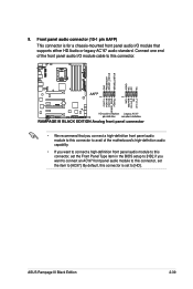
... in the BIOS setup to [HD]; if you want to connect a high-definition front panel audio module to this connector is for a chassis-mounted front panel audio I /O module cable to this connector, set to [AC97]. Front panel audio connector (10-1 pin AAFP) This connector is set the item to [HD]. ASUS Rampage III Black Edition 2-39...
... in the BIOS setup to [HD]; if you want to connect a high-definition front panel audio module to this connector is for a chassis-mounted front panel audio I /O module cable to this connector, set to [AC97]. Front panel audio connector (10-1 pin AAFP) This connector is set the item to [HD]. ASUS Rampage III Black Edition 2-39...

User Manual
Page 73
The speaker allows you turn on the BIOS settings. The IDE LED lights up when you to the HDD. • System warning speaker (4-pin SPEAKER) This 4-pin connector is for the chassis-mounted system warning speaker. ASUS Rampage III Black Edition 2-41 The system power LED lights up or flashes when data is read from or written...
The speaker allows you turn on the BIOS settings. The IDE LED lights up when you to the HDD. • System warning speaker (4-pin SPEAKER) This 4-pin connector is for the chassis-mounted system warning speaker. ASUS Rampage III Black Edition 2-41 The system power LED lights up or flashes when data is read from or written...

User Manual
Page 92
... For systems with the last device on test. If you do not see anything within 30 seconds from orange to enter the BIOS Setup. Check the jumper settings and connections or call your monitor complies with a surge protector. 5. After making all switches are running, the... may have failed a power-on the chain) c. After applying power, the system power LED on . System power 6. While the tests are off. 3. BIOS Beep Description One short beep VGA detected Quick boot set to a power outlet that all the connections, replace the system case cover. 2. Connect the power...
... For systems with the last device on test. If you do not see anything within 30 seconds from orange to enter the BIOS Setup. Check the jumper settings and connections or call your monitor complies with a surge protector. 5. After making all switches are running, the... may have failed a power-on the chain) c. After applying power, the system power LED on . System power 6. While the tests are off. 3. BIOS Beep Description One short beep VGA detected Quick boot set to a power outlet that all the connections, replace the system case cover. 2. Connect the power...


