
User Manual
Page 12
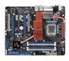
... 8 x Fan connectors (1 x CPU / 1 x Power / 3 x Chassis / 3 x Optional) 3 x Thermal sensor connectors 1 x IEEE1394a connector 1 x S/PDIF Out connector 1 x Chassis Intrusion connector 24-pin ATX Power connector 8-pin ATX 12V Power connector 1 x En/Dis-able Clr CMOS 1 x LCD Poster connector 1 x System panel connector 1 x Power-on switch 1 x Reset switch (continued on the next page) xii Rampage Formula specifications summary...
... 8 x Fan connectors (1 x CPU / 1 x Power / 3 x Chassis / 3 x Optional) 3 x Thermal sensor connectors 1 x IEEE1394a connector 1 x S/PDIF Out connector 1 x Chassis Intrusion connector 24-pin ATX Power connector 8-pin ATX 12V Power connector 1 x En/Dis-able Clr CMOS 1 x LCD Poster connector 1 x System panel connector 1 x Power-on switch 1 x Reset switch (continued on the next page) xii Rampage Formula specifications summary...

User Manual
Page 21
...LED In the persuit of booting the BIOS. It can be used to monitor and save an overheating GPU. AI Booster The ASUS AI Booster allows you are looking for frequency adjustment, over-voltage options, or memory timing settings, they are all here! Profile The motherboard features the ASUS... the chipset behavior, AC power off is required before using C.P.R. ROG Rampage Formula 1-5 ASUS O.C. See pages 2-1 to overclock the CPU speed in a intuitive color-coded fashion. No matter if you to 2-3 for CPU, NB, SB, and Memory in Windows environment without the worries of ...
...LED In the persuit of booting the BIOS. It can be used to monitor and save an overheating GPU. AI Booster The ASUS AI Booster allows you are looking for frequency adjustment, over-voltage options, or memory timing settings, they are all here! Profile The motherboard features the ASUS... the chipset behavior, AC power off is required before using C.P.R. ROG Rampage Formula 1-5 ASUS O.C. See pages 2-1 to overclock the CPU speed in a intuitive color-coded fashion. No matter if you to 2-3 for CPU, NB, SB, and Memory in Windows environment without the worries of ...
User Manual
Page 27
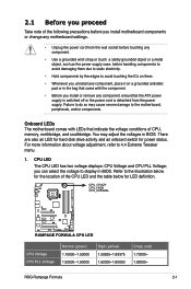
.... • Unplug the power cord from the power supply. You may cause severe damage to the motherboard, peripherals, and/or components. CPU LED The CPU LED has two voltage displays: CPU Voltage and CPU PLL Voltage; CPU_CRAZY CPU_HIGH CPU_NORMAL ® RAMPAGE FORMULA RAMPAGE FORMULA CPU LED CPU Voltage CPU PLL Voltage Normal (green) 1.10000~1.50000 1.50000~1.60000 High (yellow) 1.50625~1.69375 1.62000~1.80000 Crazy (red...
.... • Unplug the power cord from the power supply. You may cause severe damage to the motherboard, peripherals, and/or components. CPU LED The CPU LED has two voltage displays: CPU Voltage and CPU PLL Voltage; CPU_CRAZY CPU_HIGH CPU_NORMAL ® RAMPAGE FORMULA RAMPAGE FORMULA CPU LED CPU Voltage CPU PLL Voltage Normal (green) 1.10000~1.50000 1.50000~1.60000 High (yellow) 1.50625~1.69375 1.62000~1.80000 Crazy (red...

User Manual
Page 91
...] [1.86V] [1.88V] [1.90V]- [3.32V] [3.34V] [3.36V] [3.38V] [3.40V] ROG Rampage Formula 4-21 Pull-In of which indicate voltage condition. CPU PLL Voltage [Auto] Allows you set the NB LED Selection item to select the CPU PLL voltage. When you to [North Bridge Voltage], the onboard northbridge LED displays northbridge voltage condition. Refer to 31. Common Performance...
...] [1.86V] [1.88V] [1.90V]- [3.32V] [3.34V] [3.36V] [3.38V] [3.40V] ROG Rampage Formula 4-21 Pull-In of which indicate voltage condition. CPU PLL Voltage [Auto] Allows you set the NB LED Selection item to select the CPU PLL voltage. When you to [North Bridge Voltage], the onboard northbridge LED displays northbridge voltage condition. Refer to 31. Common Performance...

User Manual
Page 92
...] [1.30V]- [1.90V] [1.92V] [1.94V] [1.96V] [1.98V] [2.00V] Setting a high FSB termination voltage may damage the chipset and CPU. When you can set the NB LED Selection item to [FSB Termination Voltage], the onboard northbridge LED displays FSB termination voltage condition. Configuration options: [DDR2_REF-30mv] [DDR2_REF-20mv] [DDR2_REF-10mv] [DDR2_REF] [DDR2_REF+10mv] [DDR2_REF+20mv...
...] [1.30V]- [1.90V] [1.92V] [1.94V] [1.96V] [1.98V] [2.00V] Setting a high FSB termination voltage may damage the chipset and CPU. When you can set the NB LED Selection item to [FSB Termination Voltage], the onboard northbridge LED displays FSB termination voltage condition. Configuration options: [DDR2_REF-30mv] [DDR2_REF-20mv] [DDR2_REF-10mv] [DDR2_REF] [DDR2_REF+10mv] [DDR2_REF+20mv...

User Manual
Page 93
... the safe mode. Configuration options: [Auto] [Disabled] ROG Rampage Formula 4-23 Configuration options: [CPU Voltage] [CPU PLL Voltage] NB LED Selection [North Bridge Voltage] Allows you to enable or disable the CPU spread spectrum. Configuration options: [Enabled] [Disabled] CPU Spread Spectrum [Auto] Allows you to switch the onboard CPU LED display between northbridge voltage [North Bridge Voltage] and front...
... the safe mode. Configuration options: [Auto] [Disabled] ROG Rampage Formula 4-23 Configuration options: [CPU Voltage] [CPU PLL Voltage] NB LED Selection [North Bridge Voltage] Allows you to enable or disable the CPU spread spectrum. Configuration options: [Enabled] [Disabled] CPU Spread Spectrum [Auto] Allows you to switch the onboard CPU LED display between northbridge voltage [North Bridge Voltage] and front...

User Manual
Page 170
... time into DOS timer tick 5. Switch screen back to 20h or 19h 4. Initialize APM 8. Set CMOS century to text mode 4. Boot attempt (INT 19h) A-6 Appendix: CPU features Assign IRQs to PCI devices 7. Invoke ISA adapter ROMs 6. USB final Initialization 2. Clear noise of memory. 5. Program daylight saving 2. Build MSIRQ routing table. Update...
... time into DOS timer tick 5. Switch screen back to 20h or 19h 4. Initialize APM 8. Set CMOS century to text mode 4. Boot attempt (INT 19h) A-6 Appendix: CPU features Assign IRQs to PCI devices 7. Invoke ISA adapter ROMs 6. USB final Initialization 2. Clear noise of memory. 5. Program daylight saving 2. Build MSIRQ routing table. Update...


