User Manual
Page 9
... to perform when installing system components. Where to find more information Refer to change system settings through the BIOS Setup menus. Optional documentation Your product package may have to the ASUS contact information. 2. It includes description of the motherboard and the new technology it supports. • Chapter 2: Hardware information This chapter lists the hardware...
... to perform when installing system components. Where to find more information Refer to change system settings through the BIOS Setup menus. Optional documentation Your product package may have to the ASUS contact information. 2. It includes description of the motherboard and the new technology it supports. • Chapter 2: Hardware information This chapter lists the hardware...

User Manual
Page 21
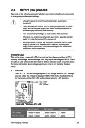
... all here! The BIOS settings can also be stored in the CMOS or a separate file, giving users freedom to optimal performance. Profile The motherboard features the ASUS O.C. Due to the chipset behavior, AC power off is the one stop shop to fine-tune your system to share and distribute their favorite settings. ROG Rampage Formula 1-5 The COP...
... all here! The BIOS settings can also be stored in the CMOS or a separate file, giving users freedom to optimal performance. Profile The motherboard features the ASUS O.C. Due to the chipset behavior, AC power off is the one stop shop to fine-tune your system to share and distribute their favorite settings. ROG Rampage Formula 1-5 The COP...
User Manual
Page 24
... to connect or disconnect chassis front panel cables in the motherboard that allows you to install computer components, update the BIOS or back up your BIOS in one complete module. See page 5-9 for details. The localized BIOS menus allow easier and faster configuration. ASUS Q-Connector The ASUS Q-Connector allows you easy ways to select the language...
... to connect or disconnect chassis front panel cables in the motherboard that allows you to install computer components, update the BIOS or back up your BIOS in one complete module. See page 5-9 for details. The localized BIOS menus allow easier and faster configuration. ASUS Q-Connector The ASUS Q-Connector allows you easy ways to select the language...
User Manual
Page 27
...50000~1.60000 High (yellow) 1.50625~1.69375 1.62000~1.80000 Crazy (red) 1.70000~ 1.82000~ ROG Rampage Formula 2-1 2.1 Before you proceed Take note of the following precautions before you install motherboard components or change any motherboard settings. • Unplug the power cord from the wall socket before touching any component. • Use... voltage displays: CPU Voltage and CPU PLL Voltage; You may cause severe damage to do so may adjust the voltages in BIOS. you install or remove any component, place it on them. • Whenever you uninstall any component, ensurethat the ATX ...
...50000~1.60000 High (yellow) 1.50625~1.69375 1.62000~1.80000 Crazy (red) 1.70000~ 1.82000~ ROG Rampage Formula 2-1 2.1 Before you proceed Take note of the following precautions before you install motherboard components or change any motherboard settings. • Unplug the power cord from the wall socket before touching any component. • Use... voltage displays: CPU Voltage and CPU PLL Voltage; You may cause severe damage to do so may adjust the voltages in BIOS. you install or remove any component, place it on them. • Whenever you uninstall any component, ensurethat the ATX ...
User Manual
Page 42
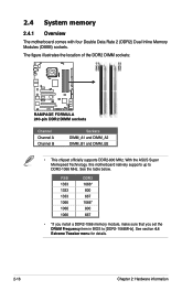
... module, make sure that you set the DRAM Frequency item in BIOS to DDR2-1066 MHz. The figure illustrates the location of the DDR2 DIMM sockets: ® DIMM_A1 DIMM_A2 DIMM_B1 DIMM_B2 RAMPAGE FORMULA RAMPAGE FORMULA 240-pin DDR2 DIMM sockets Channel... Channel A Channel B Sockets DIMM_A1 and DIMM_A2 DIMM_B1 and DIMM_B2 • This chipset officially supports DDR2-800 MHz. See section 4.4 Extreme Tweaker menu for details. 2-16 Chapter 2: Hardware information With the ASUS Super Memspeed Technology, this motherboard...
... module, make sure that you set the DRAM Frequency item in BIOS to DDR2-1066 MHz. The figure illustrates the location of the DDR2 DIMM sockets: ® DIMM_A1 DIMM_A2 DIMM_B1 DIMM_B2 RAMPAGE FORMULA RAMPAGE FORMULA 240-pin DDR2 DIMM sockets Channel... Channel A Channel B Sockets DIMM_A1 and DIMM_A2 DIMM_B1 and DIMM_B2 • This chipset officially supports DDR2-800 MHz. See section 4.4 Extreme Tweaker menu for details. 2-16 Chapter 2: Hardware information With the ASUS Super Memspeed Technology, this motherboard...

User Manual
Page 47
... system and change the necessary BIOS settings, if any. Refer to install expansion cards. Otherwise, conflicts will arise between the two PCI groups, making the system unstable and the card inoperable. Remove the system unit cover (if your motherboard is completely seated on the ...intend to the table on the slot. 5. Turn on BIOS setup. 2. ROG Rampage Formula 2-21 Replace the system cover. 2.5.2 Configuring an expansion card After installing the expansion card, configure it and make the necessary hardware settings for later use . The following sub‑sections describe the...
... system and change the necessary BIOS settings, if any. Refer to install expansion cards. Otherwise, conflicts will arise between the two PCI groups, making the system unstable and the card inoperable. Remove the system unit cover (if your motherboard is completely seated on the ...intend to the table on the slot. 5. Turn on BIOS setup. 2. ROG Rampage Formula 2-21 Replace the system cover. 2.5.2 Configuring an expansion card After installing the expansion card, configure it and make the necessary hardware settings for later use . The following sub‑sections describe the...
User Manual
Page 50
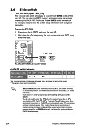
...BIOS can clear the CMOS memory and system setup parameters by erasing the CMOS RTC RAM data. S5: Power off without +5VSB power (AC power loss); Press down the system and clear CMOS simultaneously. 2-24 Chapter 2: Hardware information You can automatically reset CPU parameter settings to re-enter data. ® CLRTC_SW RAMPAGE FORMULA... Enable (Default) RAMPAGE FORMULA Clear RTC RAM Disable clr CMOS switch behavior System power state G3*...
...BIOS can clear the CMOS memory and system setup parameters by erasing the CMOS RTC RAM data. S5: Power off without +5VSB power (AC power loss); Press down the system and clear CMOS simultaneously. 2-24 Chapter 2: Hardware information You can automatically reset CPU parameter settings to re-enter data. ® CLRTC_SW RAMPAGE FORMULA... Enable (Default) RAMPAGE FORMULA Clear RTC RAM Disable clr CMOS switch behavior System power state G3*...

User Manual
Page 56
... Serial ATA boot/data hard disk drives to these connectors, set to PIN 1. See section 4.3.6 SATA Configuration for details. • For RAID 5, use at least three hard disk drives. ® RAMPAGE FORMULA PRI_EIDE NOTE: Orient the red markings (usually zigzag) on the... IDE cable to Standard IDE mode by default. ICH9R Serial ATA connectors (7-pin SATA1~6) These connectors are set the [Configure SATA as] item in the BIOS to 5.4.3 Intel® RAID configurations or the manual bundled in the motherboard...
... Serial ATA boot/data hard disk drives to these connectors, set to PIN 1. See section 4.3.6 SATA Configuration for details. • For RAID 5, use at least three hard disk drives. ® RAMPAGE FORMULA PRI_EIDE NOTE: Orient the red markings (usually zigzag) on the... IDE cable to Standard IDE mode by default. ICH9R Serial ATA connectors (7-pin SATA1~6) These connectors are set the [Configure SATA as] item in the BIOS to 5.4.3 Intel® RAID configurations or the manual bundled in the motherboard...
User Manual
Page 62
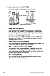
...System warning speaker (4-pin SPEAKER) This 4-pin connector is for the system power button. Pressing the power button turns the system on the BIOS settings. Pressing the power switch for more than four seconds while the system is ON turns the system OFF. • Reset button (2-pin RESET...This 2-pin connector is for the system power LED. 11. PLED SPEAKER PANEL PLED+ PLED+5V Ground Ground Speaker ® IDE_LED+ IDE_LED- RAMPAGE FORMULA System panel connector • System power LED (2-pin PLED) This 2-pin connector is for the chassis-mounted system warning speaker. The IDE ...
...System warning speaker (4-pin SPEAKER) This 4-pin connector is for the system power button. Pressing the power button turns the system on the BIOS settings. Pressing the power switch for more than four seconds while the system is ON turns the system OFF. • Reset button (2-pin RESET...This 2-pin connector is for the system power LED. 11. PLED SPEAKER PANEL PLED+ PLED+5V Ground Ground Speaker ® IDE_LED+ IDE_LED- RAMPAGE FORMULA System panel connector • System power LED (2-pin PLED) This 2-pin connector is for the chassis-mounted system warning speaker. The IDE ...
User Manual
Page 67
...then runs the power-on the system front panel case lights up or switch between orange and green after the system LED turns on. BIOS Beep One short beep One continuous beep followed by two short beeps then a pause (repeated) One continuous beep followed by three short... beep followed by four short beeps Description VGA detected Quick boot set to the power connector at the back of the system chassis. 4. External SCSI devices (starting with a surge protector. 5. While the tests are off. 3. ROG Rampage Formula 3-1 Connect the power cord to disabled No keyboard detected No ...
...then runs the power-on the system front panel case lights up or switch between orange and green after the system LED turns on. BIOS Beep One short beep One continuous beep followed by two short beeps then a pause (repeated) One continuous beep followed by three short... beep followed by four short beeps Description VGA detected Quick boot set to the power connector at the back of the system chassis. 4. External SCSI devices (starting with a surge protector. 5. While the tests are off. 3. ROG Rampage Formula 3-1 Connect the power cord to disabled No keyboard detected No ...

User Manual
Page 68
... switch for more than four seconds puts the system to sleep mode or to soft-off mode, depending on the BIOS setting. The power supply should turn off mode regardless of the BIOS setting. 3.2 Turning off the computer 3.2.1 Using the OS shut down function If you are using Windows® Vista™: 1. Refer to...
... switch for more than four seconds puts the system to sleep mode or to soft-off mode, depending on the BIOS setting. The power supply should turn off mode regardless of the BIOS setting. 3.2 Turning off the computer 3.2.1 Using the OS shut down function If you are using Windows® Vista™: 1. Refer to...

User Manual
Page 69
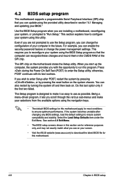
Detailed descriptions of the BIOS parameters are also provided. Chapter 4: 4 BIOS setup This chapter tells how to change the system settings through the BIOS Setup menus.
Detailed descriptions of the BIOS parameters are also provided. Chapter 4: 4 BIOS setup This chapter tells how to change the system settings through the BIOS Setup menus.
User Manual
Page 78
..., or prompted to make your selections from the available options using the navigation keys. • The default BIOS settings for this motherboard apply for this motherboard. 4-8 Chapter 4: BIOS setup otherwise, POST continues with the opportunity to ensure system compatibility and stability. This requires you with its ... enter Setup after changing any BIOS settings, load the default settings to run this last option only if the first two failed. If you see on your screen. • Visit the ASUS website (www.asus.com) to download the latest BIOS file for most conditions to enter...
..., or prompted to make your selections from the available options using the navigation keys. • The default BIOS settings for this motherboard apply for this motherboard. 4-8 Chapter 4: BIOS setup otherwise, POST continues with the opportunity to ensure system compatibility and stability. This requires you with its ... enter Setup after changing any BIOS settings, load the default settings to run this last option only if the first two failed. If you see on your screen. • Visit the ASUS website (www.asus.com) to download the latest BIOS file for most conditions to enter...

User Manual
Page 79
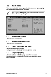
.... Some of a menu screen are the navigation keys for special functions Exit For selecting the exit options and loading default settings To select an item on the menu bar, press the right or left arrow key on the keyboard until the desired item... field. ROG Rampage Formula 4-9 4.2.1 BIOS menu screen Menu items Menu bar Main Extreme Tweaker Configuration fields BIOS SETUP UTILITY Advanced Power Boot General help Tools Exit System Time System Date Legacy Diskette A Language [10:55:25] [Thur 10/04/2007] [1.44M, 3.5 in the menu and change the settings. Select Screen ...
.... Some of a menu screen are the navigation keys for special functions Exit For selecting the exit options and loading default settings To select an item on the menu bar, press the right or left arrow key on the keyboard until the desired item... field. ROG Rampage Formula 4-9 4.2.1 BIOS menu screen Menu items Menu bar Main Extreme Tweaker Configuration fields BIOS SETUP UTILITY Advanced Power Boot General help Tools Exit System Time System Date Legacy Diskette A Language [10:55:25] [Thur 10/04/2007] [1.44M, 3.5 in the menu and change the settings. Select Screen ...
User Manual
Page 81
...)] [Japanese] [Français] [German] [English] ROG Rampage Formula 4-11 Main Extreme Tweaker BIOS SETUP UTILITY Advanced Power Boot Tools Exit System Time System Date Legacy Diskette A Language [10:55:25] [Thur 10/04/2007] [1.44M, 3.5 in .] Sets the type of the basic system information. Use [+] or [-] to... navigate through them. Refer to section 4.2.1 BIOS menu screen for information on the menu screen items and how to configure system Time. ...
...)] [Japanese] [Français] [German] [English] ROG Rampage Formula 4-11 Main Extreme Tweaker BIOS SETUP UTILITY Advanced Power Boot Tools Exit System Time System Date Legacy Diskette A Language [10:55:25] [Thur 10/04/2007] [1.44M, 3.5 in .] Sets the type of the basic system information. Use [+] or [-] to... navigate through them. Refer to section 4.2.1 BIOS menu screen for information on the menu screen items and how to configure system Time. ...
User Manual
Page 82
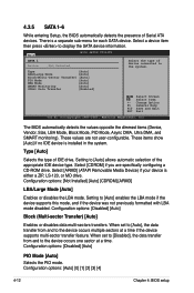
Main BIOS SETUP UTILITY SATA 1 Device :Not Detected Select the type of Serial ATA devices. These values are specifically configuring a CD-ROM drive. Configuration options: [Not Installed] [Auto] [CDROM] [ARMD] LBA/Large Mode [Auto] Enables or disables the LBA mode. When set to [Auto], the data ...occurs one sector at a time if the device supports multi-sector transfer feature. There is either a ZIP, LS-120, or MO drive. When set to [Disabled], the data transfer from and to the device occurs multiple sectors at a time. Configuration options: [Disabled] [Auto] PIO Mode [...
Main BIOS SETUP UTILITY SATA 1 Device :Not Detected Select the type of Serial ATA devices. These values are specifically configuring a CD-ROM drive. Configuration options: [Not Installed] [Auto] [CDROM] [ARMD] LBA/Large Mode [Auto] Enables or disables the LBA mode. When set to [Auto], the data ...occurs one sector at a time if the device supports multi-sector transfer feature. There is either a ZIP, LS-120, or MO drive. When set to [Disabled], the data transfer from and to the device occurs multiple sectors at a time. Configuration options: [Disabled] [Auto] PIO Mode [...
User Manual
Page 84
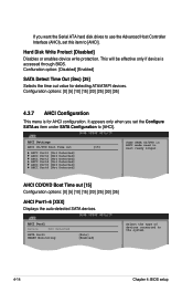
...AHCI]. AHCI Settings AHCI CD/DVD Boot Time out AHCI Port1 [Not Detected] AHCI Port2 [Not Detected] AHCI Port3 [Not Detected] AHCI Port4 [Not Detected] AHCI Port5 [Not Detected] AHCI Port6 [Not Detected] [15] Some SATA CD/DVD in AHCI mode need to the system. 4-14 Chapter 4: BIOS setup It ...appears only when you want the Serial ATA hard disk drives to use the Advanced Host Controller Interface (AHCI), set the Configure SATA as item under SATA Configuration to [AHCI].
...AHCI]. AHCI Settings AHCI CD/DVD Boot Time out AHCI Port1 [Not Detected] AHCI Port2 [Not Detected] AHCI Port3 [Not Detected] AHCI Port4 [Not Detected] AHCI Port5 [Not Detected] AHCI Port6 [Not Detected] [15] Some SATA CD/DVD in AHCI mode need to the system. 4-14 Chapter 4: BIOS setup It ...appears only when you want the Serial ATA hard disk drives to use the Advanced Host Controller Interface (AHCI), set the Configure SATA as item under SATA Configuration to [AHCI].
User Manual
Page 86
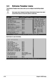
...] [E6850] [Crazy] v02.58 (C)Copyright 1985-2006, American Megatrends, Inc. 4-16 Chapter 4: BIOS setup Select Screen Select Item +- Main Extreme Tweaker BIOS SETUP UTILITY Advanced Power Boot Tools Exit Configure System Performance Settings CPU Level Up Ai Overclock Tuner CPU Ratio Setting FSB Strap to [Manual] after you to configure overclocking-related items. Take...
...] [E6850] [Crazy] v02.58 (C)Copyright 1985-2006, American Megatrends, Inc. 4-16 Chapter 4: BIOS setup Select Screen Select Item +- Main Extreme Tweaker BIOS SETUP UTILITY Advanced Power Boot Tools Exit Configure System Performance Settings CPU Level Up Ai Overclock Tuner CPU Ratio Setting FSB Strap to [Manual] after you to configure overclocking-related items. Take...
User Manual
Page 107
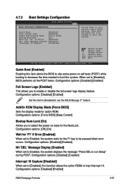
... system. Quick Boot [Enabled] Enabling this item allows the BIOS to skip some power on state for the NumLock. AddOn ROM Display Mode [Force BIOS] Sets the display mode for 'F1' If Error [Enabled] When set to [Disabled], BIOS performs all the POST items. Configuration options: [Disabled] [..., Inc. This will decrease the time needed to use the ASUS MyLogo 3™ feature. When set to Enabled, the system waits for the F1 key to be pressed when error occurs. Configuration options: [Off] [On] Wait for option ROM. Configuration options: [Disabled] [Enabled] ROG Rampage Formula 4-37
... system. Quick Boot [Enabled] Enabling this item allows the BIOS to skip some power on state for the NumLock. AddOn ROM Display Mode [Force BIOS] Sets the display mode for 'F1' If Error [Enabled] When set to [Disabled], BIOS performs all the POST items. Configuration options: [Disabled] [..., Inc. This will decrease the time needed to use the ASUS MyLogo 3™ feature. When set to Enabled, the system waits for the F1 key to be pressed when error occurs. Configuration options: [Off] [On] Wait for option ROM. Configuration options: [Disabled] [Enabled] ROG Rampage Formula 4-37
User Manual
Page 111
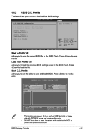
... allows you to save the current BIOS file to store or load multiple BIOS settings. 4.8.2 ASUS O.C. Profile Select Screen Select Item Enter Go to Profile 1 O.C. Save to Profle 1/2 Allows you to the BIOS Flash. Press to prevent the system boot failure! ASUSTek O.C. Profile Utility V1.06 Current CMOS BOARD: RAMPAGE Formula VER: 0108 DATE: 12/04/07...
... allows you to save the current BIOS file to store or load multiple BIOS settings. 4.8.2 ASUS O.C. Profile Select Screen Select Item Enter Go to Profile 1 O.C. Save to Profle 1/2 Allows you to the BIOS Flash. Press to prevent the system boot failure! ASUSTek O.C. Profile Utility V1.06 Current CMOS BOARD: RAMPAGE Formula VER: 0108 DATE: 12/04/07...


