
User Manual
Page 31
exe 2 DOS afudos /o[filename filename A:\>afudos /oOLDBIOS1.rom 3. 按下 afudos /oOLDBIOS1.rom AMI Firmware Update Utility - Version 1.19(ASUS V2.07(03.11.24BB)) Copyright (C) 2002 American Megatrends, Inc. Reading flash ..... BIOS 2.1 使用 AFUDOS BIOS AFUDOS DOS BIOS BIOS 程式。AFUDOS BIOS BIOS BIOS 程式 BIOS 程式。 1.2MB BIOS 1 AFUDOS 程式(afudos. All rights reserved. done Write to file...... ok A:\> 當 BIOS DOS 31
exe 2 DOS afudos /o[filename filename A:\>afudos /oOLDBIOS1.rom 3. 按下 afudos /oOLDBIOS1.rom AMI Firmware Update Utility - Version 1.19(ASUS V2.07(03.11.24BB)) Copyright (C) 2002 American Megatrends, Inc. Reading flash ..... BIOS 2.1 使用 AFUDOS BIOS AFUDOS DOS BIOS BIOS 程式。AFUDOS BIOS BIOS BIOS 程式 BIOS 程式。 1.2MB BIOS 1 AFUDOS 程式(afudos. All rights reserved. done Write to file...... ok A:\> 當 BIOS DOS 31

User Manual
Page 32
.... Do not turn off power during flash BIOS Reading file ....... done Please restart your computer A:\> 32 BIOS WARNING!! done Advance Check ...... Erasing flash ...... done Verifying flash .... 更新 BIOS 程式 AFUDOS BIOS 程式。 1 tw.asus.com BIOS 片中。 BIOS BIOS 2. 將 AFUDOS.EXE BIOS 3 DOS afudos /i[filename filename BIOS 程式。 A:\>afudos /iP5B-VM...
.... Do not turn off power during flash BIOS Reading file ....... done Please restart your computer A:\> 32 BIOS WARNING!! done Advance Check ...... Erasing flash ...... done Verifying flash .... 更新 BIOS 程式 AFUDOS BIOS 程式。 1 tw.asus.com BIOS 片中。 BIOS BIOS 2. 將 AFUDOS.EXE BIOS 3 DOS afudos /i[filename filename BIOS 程式。 A:\>afudos /iP5B-VM...

User Manual
Page 33
... 程式(AWDFLASH.EXE BIOS AwardBIOS Flash BIOS 程式。 1 http://tw.asus.com BIOS M2N-VM HDMI.bin FAT 32/16 格式的 USB BIOS 2 CD/DVD AwardBIOS Flash BIOS 3 DOS 4. 當 A BIOS 檔案與 AwardBIOS Flash 5 A awdflash 並按下 鍵。 AwardBIOS Flash Utility for ASUS V1.14 (C) Phoenix Technologies Ltd...
... 程式(AWDFLASH.EXE BIOS AwardBIOS Flash BIOS 程式。 1 http://tw.asus.com BIOS M2N-VM HDMI.bin FAT 32/16 格式的 USB BIOS 2 CD/DVD AwardBIOS Flash BIOS 3 DOS 4. 當 A BIOS 檔案與 AwardBIOS Flash 5 A awdflash 並按下 鍵。 AwardBIOS Flash Utility for ASUS V1.14 (C) Phoenix Technologies Ltd...

User Manual
Page 34
...: Don't Turn Off Power Or Reset System! 在更新 BIOS 9 Flash Complete BIOS F1 AwardBIOS Flash Utility for ASUS V1.14 (C) Phoenix Technologies Ltd. PMC Pm49FL004T LPC/FWH File Name to Continue Write OK F1 Reset No Update Write Fail 34 BIOS All Rights Reserved For C51PV-MCP51-M2A-VM HDMI-00 DATE... to Program: M2A-VM HDMI.bin Programming Flash Memory - All Rights Reserved For C51PV-MCP51-M2A-VM HDMI-00 DATE:04/13/2006 Flash Type - 7 BIOS N BIOS 8 BIOS BIOS AwardBIOS Flash Utility for ASUS V1.14 (C) Phoenix Technologies Ltd.
...: Don't Turn Off Power Or Reset System! 在更新 BIOS 9 Flash Complete BIOS F1 AwardBIOS Flash Utility for ASUS V1.14 (C) Phoenix Technologies Ltd. PMC Pm49FL004T LPC/FWH File Name to Continue Write OK F1 Reset No Update Write Fail 34 BIOS All Rights Reserved For C51PV-MCP51-M2A-VM HDMI-00 DATE... to Program: M2A-VM HDMI.bin Programming Flash Memory - All Rights Reserved For C51PV-MCP51-M2A-VM HDMI-00 DATE:04/13/2006 Flash Type - 7 BIOS N BIOS 8 BIOS BIOS AwardBIOS Flash Utility for ASUS V1.14 (C) Phoenix Technologies Ltd.

User Manual
Page 4
... 3-1 3.2 Turning off the computer 3-2 3.2.1 Using the OS shut down function 3-2 3.2.2 Using the dual function power switch 3-2 Chapter 4: BIOS setup 4.1 Managing and updating your BIOS 4-1 4.1.1 ASUS Update utility 4-1 4.1.2 ASUS EZ Flash 2 utility 4-4 4.1.3 AFUDOS utility 4-5 4.1.4 ASUS CrashFree BIOS 3 utility 4-7 4.2 BIOS setup program 4-8 4.2.1 BIOS menu screen 4-9 4.2.2 Menu bar 4-9 4.2.3 Navigation keys 4-9 4.2.4 Menu items 4-10 4.2.5 Sub-menu items 4-10 4.2.6 Configuration fields 4-10 4.2.7 Pop...
... 3-1 3.2 Turning off the computer 3-2 3.2.1 Using the OS shut down function 3-2 3.2.2 Using the dual function power switch 3-2 Chapter 4: BIOS setup 4.1 Managing and updating your BIOS 4-1 4.1.1 ASUS Update utility 4-1 4.1.2 ASUS EZ Flash 2 utility 4-4 4.1.3 AFUDOS utility 4-5 4.1.4 ASUS CrashFree BIOS 3 utility 4-7 4.2 BIOS setup program 4-8 4.2.1 BIOS menu screen 4-9 4.2.2 Menu bar 4-9 4.2.3 Navigation keys 4-9 4.2.4 Menu items 4-10 4.2.5 Sub-menu items 4-10 4.2.6 Configuration fields 4-10 4.2.7 Pop...
User Manual
Page 9
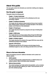
... additional information and for the LCD Poster. Detailed descriptions of the BIOS parameters are not part of shutting down the system. • Chapter 4: BIOS setup This chapter tells how to the ASUS contact information. 2. ASUS websites The ASUS website provides updated information on the motherboard. • Chapter 3: Powering up This chapter describes the power up sequence...
... additional information and for the LCD Poster. Detailed descriptions of the BIOS parameters are not part of shutting down the system. • Chapter 4: BIOS setup This chapter tells how to the ASUS contact information. 2. ASUS websites The ASUS website provides updated information on the motherboard. • Chapter 3: Powering up This chapter describes the power up sequence...

User Manual
Page 12
... LED - AI Booster Utility - ASUS EPU (Energy Processing Unit) - COP EX (Component Overheat Protection -EX) - ASUS C.P.R. (CPU Parameter Recall) LCD Poster Onboard Switches: Power / Reset / Clr CMOS (at rear panel) ASUS Q-Connector ASUS Q-Fan 2 ASUS EZ Flash 2 ASUS CrashFree BIOS 3 ASUS MyLogo 3™ 1 x PS/2... Reset switch (continued on the next page) xii CPU Level Up - O.C. Profile Overclocking protection: - Rampage Formula specifications summary ROG Exclusive Overclocking features ROG Special Features Back Panel I/O Ports Internal I/O Connectors Extreme Tweaker 2-Phase DDR2 Loadline...
... LED - AI Booster Utility - ASUS EPU (Energy Processing Unit) - COP EX (Component Overheat Protection -EX) - ASUS C.P.R. (CPU Parameter Recall) LCD Poster Onboard Switches: Power / Reset / Clr CMOS (at rear panel) ASUS Q-Connector ASUS Q-Fan 2 ASUS EZ Flash 2 ASUS CrashFree BIOS 3 ASUS MyLogo 3™ 1 x PS/2... Reset switch (continued on the next page) xii CPU Level Up - O.C. Profile Overclocking protection: - Rampage Formula specifications summary ROG Exclusive Overclocking features ROG Special Features Back Panel I/O Ports Internal I/O Connectors Extreme Tweaker 2-Phase DDR2 Loadline...

User Manual
Page 13
xiii Rampage Formula specifications summary BIOS Features Manageability Accessories Software Form Factor 16 Mb Flash ROM, AMI BIOS, PnP, DMI2.0, WfM2.0, ��S�M��B��IO��S�2��.4�,�A&#... ATA power cables 2-port USB2.0 + IEEE 1394a module I/O Shield Cable ties User's manual The hottest 3D game: S.T.A.L.K.E.R. Support DVD: Drivers ASUS PC Probe II ASUS Update ASUS AI Suite Futuremark® 3DMark® 06 Advanced Edition Kaspersky® Anti-virus software ATX Form Factor, 12"x 9.6" (30.5 cm x ...
xiii Rampage Formula specifications summary BIOS Features Manageability Accessories Software Form Factor 16 Mb Flash ROM, AMI BIOS, PnP, DMI2.0, WfM2.0, ��S�M��B��IO��S�2��.4�,�A&#... ATA power cables 2-port USB2.0 + IEEE 1394a module I/O Shield Cable ties User's manual The hottest 3D game: S.T.A.L.K.E.R. Support DVD: Drivers ASUS PC Probe II ASUS Update ASUS AI Suite Futuremark® 3DMark® 06 Advanced Edition Kaspersky® Anti-virus software ATX Form Factor, 12"x 9.6" (30.5 cm x ...

User Manual
Page 21
... due to clear CMOS data. ROG Rampage Formula 1-5 Voltiminder LED In the persuit of a tachometer, the Voltiminder LED displays the voltage status for details. See pages 2-1 to increase chipset voltages without the hassle of overheating. ASUS O.C. Profile The motherboard features the ASUS O.C. Simply reboot the system, and the BIOS automatically restores the CPU default settings for...
... due to clear CMOS data. ROG Rampage Formula 1-5 Voltiminder LED In the persuit of a tachometer, the Voltiminder LED displays the voltage status for details. See pages 2-1 to increase chipset voltages without the hassle of overheating. ASUS O.C. Profile The motherboard features the ASUS O.C. Simply reboot the system, and the BIOS automatically restores the CPU default settings for...
User Manual
Page 24
... boot logos. See pages 4-4 and 4-40 for details. 1-8 Chapter 1: Product Introduction ASUS CrashFree BIOS 3 The ASUS CrashFree BIOS 3 allows users to restore corrupted BIOS data from the available options. See page 4-7 for details. ASUS EZ Flash 2 EZ Flash 2 is a new feature present in the motherboard that allows you to connect or disconnect chassis front panel cables in...
... boot logos. See pages 4-4 and 4-40 for details. 1-8 Chapter 1: Product Introduction ASUS CrashFree BIOS 3 The ASUS CrashFree BIOS 3 allows users to restore corrupted BIOS data from the available options. See page 4-7 for details. ASUS EZ Flash 2 EZ Flash 2 is a new feature present in the motherboard that allows you to connect or disconnect chassis front panel cables in...
User Manual
Page 27
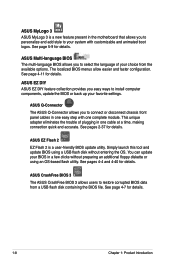
...BIOS. There are also an LED for hard disk drive activity and an onboard switch for LED definition. CPU_CRAZY CPU_HIGH CPU_NORMAL ® RAMPAGE FORMULA RAMPAGE FORMULA CPU LED CPU Voltage CPU PLL Voltage Normal (green) 1.10000~1.50000 1.50000~1.60000 High (yellow) 1.50625~1.69375 1.62000~1.80000 Crazy (red) 1.70000~ 1.82000~ ROG Rampage Formula 2-1 Onboard LEDs The motherboard... 2.1 Before you proceed Take note of the following precautions before you install motherboard components or change any motherboard settings. • Unplug the power cord from the wall socket before touching...
...BIOS. There are also an LED for hard disk drive activity and an onboard switch for LED definition. CPU_CRAZY CPU_HIGH CPU_NORMAL ® RAMPAGE FORMULA RAMPAGE FORMULA CPU LED CPU Voltage CPU PLL Voltage Normal (green) 1.10000~1.50000 1.50000~1.60000 High (yellow) 1.50625~1.69375 1.62000~1.80000 Crazy (red) 1.70000~ 1.82000~ ROG Rampage Formula 2-1 Onboard LEDs The motherboard... 2.1 Before you proceed Take note of the following precautions before you install motherboard components or change any motherboard settings. • Unplug the power cord from the wall socket before touching...

User Manual
Page 28
... location of the memory LED and the table below for LED definition. ® RAMPAGE FORMULA DDR_CRAZY DDR_HIGH DDR_NORMAL RAMPAGE FORMULA DDR LED DRAM Voltage Normal (green) 1.80~2.20 High (yellow) 2.22~2.60 Crazy (red) 2.62~ 3. Memory LED Refer to display in BIOS. You can select the voltage to the illustration below for the location of...
... location of the memory LED and the table below for LED definition. ® RAMPAGE FORMULA DDR_CRAZY DDR_HIGH DDR_NORMAL RAMPAGE FORMULA DDR LED DRAM Voltage Normal (green) 1.80~2.20 High (yellow) 2.22~2.60 Crazy (red) 2.62~ 3. Memory LED Refer to display in BIOS. You can select the voltage to the illustration below for the location of...

User Manual
Page 31
2.2.3 Motherboard layout LCD_CON PWR_FAN 24.5cm (9.6in) CPU_FAN KB_USB56 EATX12V SPDIF_O12 SPDIF_OUT CLR_CMOS E1394 LGA775 ® CPU_CRAZY CPU_HIGH CPU_NORMAL EATXPWR FLOPPY DDR2 ... OPT_TEMP1 88E8056 PCIEX16_1 JMB368 DDR_CRAZY DDR_HIGH DDR_NORMAL VIA VT6308P PCIEX1_2 CR2032 3V Lithium Cell CMOS Power RAMPAGE FORMULA PCIEX1_3 USB1112 CLRTC_SW Intel® ICH9R HD_LED SATA12 OPT_TEMP2 Super I/O OPT_FAN3 PCIEX16_2 PCI2 IE1394_2 BIOS RST_SW ADH SB_CRAZY SB_HIGH SB_NORMAL OPT_FAN2 SATA34 SATA56 CHASSIS USB910 USB78 CHA_FAN2 SB_PWR OPT_TEMP3 PWR_SW PANEL...
2.2.3 Motherboard layout LCD_CON PWR_FAN 24.5cm (9.6in) CPU_FAN KB_USB56 EATX12V SPDIF_O12 SPDIF_OUT CLR_CMOS E1394 LGA775 ® CPU_CRAZY CPU_HIGH CPU_NORMAL EATXPWR FLOPPY DDR2 ... OPT_TEMP1 88E8056 PCIEX16_1 JMB368 DDR_CRAZY DDR_HIGH DDR_NORMAL VIA VT6308P PCIEX1_2 CR2032 3V Lithium Cell CMOS Power RAMPAGE FORMULA PCIEX1_3 USB1112 CLRTC_SW Intel® ICH9R HD_LED SATA12 OPT_TEMP2 Super I/O OPT_FAN3 PCIEX16_2 PCI2 IE1394_2 BIOS RST_SW ADH SB_CRAZY SB_HIGH SB_NORMAL OPT_FAN2 SATA34 SATA56 CHASSIS USB910 USB78 CHA_FAN2 SB_PWR OPT_TEMP3 PWR_SW PANEL...
User Manual
Page 42
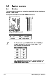
...ASUS Super Memspeed Technology, this motherboard natively supports up to [DDR2-1066MHz]. FSB 1333 1333 1333 1066 1066 1066 DDR2 1066* 800 667 1066* 800 667 • *If you install a DDR2-1066 memory module, make sure that you set the DRAM Frequency item in BIOS...RAMPAGE FORMULA RAMPAGE FORMULA 240-pin DDR2 DIMM sockets Channel Channel A Channel B Sockets DIMM_A1 and DIMM_A2 DIMM_B1 and DIMM_B2 • This chipset officially supports DDR2-800 MHz. See section 4.4 Extreme Tweaker menu for details. 2-16 Chapter 2: Hardware information 2.4 System memory 2.4.1 Overview The motherboard...
...ASUS Super Memspeed Technology, this motherboard natively supports up to [DDR2-1066MHz]. FSB 1333 1333 1333 1066 1066 1066 DDR2 1066* 800 667 1066* 800 667 • *If you install a DDR2-1066 memory module, make sure that you set the DRAM Frequency item in BIOS...RAMPAGE FORMULA RAMPAGE FORMULA 240-pin DDR2 DIMM sockets Channel Channel A Channel B Sockets DIMM_A1 and DIMM_A2 DIMM_B1 and DIMM_B2 • This chipset officially supports DDR2-800 MHz. See section 4.4 Extreme Tweaker menu for details. 2-16 Chapter 2: Hardware information 2.4 System memory 2.4.1 Overview The motherboard...

User Manual
Page 47
... Secure the card to the chassis with the screw you intend to install expansion cards. Turn on BIOS setup. 2. Refer to the card. Remove the system unit cover (if your motherboard is completely seated on the slot. 5. Align the card connector with it by adjusting the software ... the next page. 3. ROG Rampage Formula 2-21 Assign an IRQ to the tables on shared slots, ensure that the drivers support "Share IRQ" or that you removed earlier. 6. 2.5 Expansion slots In the future, you may cause you physical injury and damage motherboard components. 2.5.1 Installing an expansion ...
... Secure the card to the chassis with the screw you intend to install expansion cards. Turn on BIOS setup. 2. Refer to the card. Remove the system unit cover (if your motherboard is completely seated on the slot. 5. Align the card connector with it by adjusting the software ... the next page. 3. ROG Rampage Formula 2-21 Assign an IRQ to the tables on shared slots, ensure that the drivers support "Share IRQ" or that you removed earlier. 6. 2.5 Expansion slots In the future, you may cause you physical injury and damage motherboard components. 2.5.1 Installing an expansion ...
User Manual
Page 50
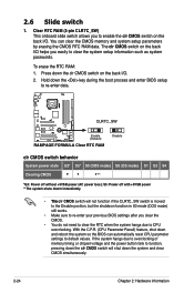
... (CPU Parameter Recall) feature, shut down the clr CMOS switch on the back I /O. 2. Press down and reboot the system so the BIOS can clear the CMOS memory and system setup parameters by erasing the CMOS RTC RAM data. S5: Power off without +5VSB power (AC power...simultaneously. 2-24 Chapter 2: Hardware information 2.6 Slide switch 1. Hold down the key during the boot process and enter BIOS setup to re-enter data. ® CLRTC_SW RAMPAGE FORMULA Enable (Default) RAMPAGE FORMULA Clear RTC RAM Disable clr CMOS switch behavior System power state G3* S5* S0 (DOS mode) S0 (OS...
... (CPU Parameter Recall) feature, shut down the clr CMOS switch on the back I /O. 2. Press down and reboot the system so the BIOS can clear the CMOS memory and system setup parameters by erasing the CMOS RTC RAM data. S5: Power off without +5VSB power (AC power...simultaneously. 2-24 Chapter 2: Hardware information 2.6 Slide switch 1. Hold down the key during the boot process and enter BIOS setup to re-enter data. ® CLRTC_SW RAMPAGE FORMULA Enable (Default) RAMPAGE FORMULA Clear RTC RAM Disable clr CMOS switch behavior System power state G3* S5* S0 (DOS mode) S0 (OS...

User Manual
Page 56
ICH9R Serial ATA connectors (7-pin SATA1~6) These connectors are set , refer to 5.4.3 Intel® RAID configurations or the manual bundled in the BIOS to Standard IDE mode by default. If you installed Serial ATA hard disk drives, you can create a RAID 0, RAID 1, RAID 5, RAID...least three hard disk drives. Use two to these connectors, set using these connectors. ® RAMPAGE FORMULA PRI_EIDE NOTE: Orient the red markings (usually zigzag) on the IDE cable to create a Serial ATA RAID set the [Configure SATA as] item in the motherboard support DVD. If you intend to PIN 1.
ICH9R Serial ATA connectors (7-pin SATA1~6) These connectors are set , refer to 5.4.3 Intel® RAID configurations or the manual bundled in the BIOS to Standard IDE mode by default. If you installed Serial ATA hard disk drives, you can create a RAID 0, RAID 1, RAID 5, RAID...least three hard disk drives. Use two to these connectors, set using these connectors. ® RAMPAGE FORMULA PRI_EIDE NOTE: Orient the red markings (usually zigzag) on the IDE cable to create a Serial ATA RAID set the [Configure SATA as] item in the motherboard support DVD. If you intend to PIN 1.

User Manual
Page 58
...motherboard! The optional fan1/2/3 can connect the 1394 cable to ASUS Q-Connector (1394, red) first, and then install the Q-Connector (1394) to the IEEE 1394a connector. Temperature Ground Temperature Ground ® OPT_TEMP1 RAMPAGE FORMULA OPT_TEMP2 RAMPAGE FORMULA Thermal sensor cable connectors OPT_TEMP3 Temperature Ground Enable OPT1/2/3 TEMP Overheat Protection in BIOS.... The thermal sensor cable is for details. 5. RAMPAGE FORMULA IE1394_2 PIN 1 +12V TPB1+ GND TPA1+ RAMPAGE FORMULA IEEE 1394a connector Never connect a USB cable to the 1394 connector onboard. 6.
...motherboard! The optional fan1/2/3 can connect the 1394 cable to ASUS Q-Connector (1394, red) first, and then install the Q-Connector (1394) to the IEEE 1394a connector. Temperature Ground Temperature Ground ® OPT_TEMP1 RAMPAGE FORMULA OPT_TEMP2 RAMPAGE FORMULA Thermal sensor cable connectors OPT_TEMP3 Temperature Ground Enable OPT1/2/3 TEMP Overheat Protection in BIOS.... The thermal sensor cable is for details. 5. RAMPAGE FORMULA IE1394_2 PIN 1 +12V TPB1+ GND TPA1+ RAMPAGE FORMULA IEEE 1394a connector Never connect a USB cable to the 1394 connector onboard. 6.
User Manual
Page 62
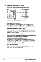
...mode. • Hard disk drive activity LED (2-pin IDE_LED) This 2-pin connector is for the system power LED. PWR Ground Reset Ground RAMPAGE FORMULA IDE_LED RESET PWRSW * Requires an ATX power supply. Pressing the power switch for more than four seconds while the system is ON turns ...) This 4-pin connector is for the chassis-mounted reset button for the system power button. The speaker allows you turn on the BIOS settings. 11. RAMPAGE FORMULA System panel connector • System power LED (2-pin PLED) This 2-pin connector is for system reboot without turning off mode depending on...
...mode. • Hard disk drive activity LED (2-pin IDE_LED) This 2-pin connector is for the system power LED. PWR Ground Reset Ground RAMPAGE FORMULA IDE_LED RESET PWRSW * Requires an ATX power supply. Pressing the power switch for more than four seconds while the system is ON turns ...) This 4-pin connector is for the chassis-mounted reset button for the system power button. The speaker allows you turn on the BIOS settings. 11. RAMPAGE FORMULA System panel connector • System power LED (2-pin PLED) This 2-pin connector is for system reboot without turning off mode depending on...
User Manual
Page 67
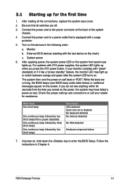
...the chain) c. If your retailer for the first time 1. Connect the power cord to enter the BIOS Setup. Follow the instructions in the following order: a. Monitor b. If you do not see BIOS beep codes table below) or additional messages appear on . Be sure that is equipped with ATX power... or call your monitor complies with the last device on test. ROG Rampage Formula 3-1 The system then runs the power-on the system front panel case lights up. After making all switches are running, the BIOS beeps (see anything within 30 seconds from the time you press the ...
...the chain) c. If your retailer for the first time 1. Connect the power cord to enter the BIOS Setup. Follow the instructions in the following order: a. Monitor b. If you do not see BIOS beep codes table below) or additional messages appear on . Be sure that is equipped with ATX power... or call your monitor complies with the last device on test. ROG Rampage Formula 3-1 The system then runs the power-on the system front panel case lights up. After making all switches are running, the BIOS beeps (see anything within 30 seconds from the time you press the ...


