User Guide
Page 4
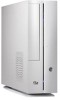
... 3-2 3.3 Support CD information 3-2 3.3.1 Running the support CD 3-3 3.3.2 Utilities menu 3-4 3.3.3 ASUS contact information 3-5 3.4 Software information 3-5 3.4.1 ASUS PC Probe II 3-5 3.4.2 DTS function 3-12 Chapter 4: Motherboard Info 4.1 Introduction 4-2 4.2 Motherboard layout 4-2 4.3 Jumpers 4-3 4.4 Connectors 4-5 Chapter 5: BIOS Information 5.1 Managing and updating your BIOS 5-2 5.1.1 ASUS Update utility 5-2 5.1.2 Creating a bootable floppy disk 5-5 5.1.3 ASUS EZ Flash utility 5-5 5.1.4 AwardBIOS Flash utility 5-7 5.1.5 Saving the current BIOS...
... 3-2 3.3 Support CD information 3-2 3.3.1 Running the support CD 3-3 3.3.2 Utilities menu 3-4 3.3.3 ASUS contact information 3-5 3.4 Software information 3-5 3.4.1 ASUS PC Probe II 3-5 3.4.2 DTS function 3-12 Chapter 4: Motherboard Info 4.1 Introduction 4-2 4.2 Motherboard layout 4-2 4.3 Jumpers 4-3 4.4 Connectors 4-5 Chapter 5: BIOS Information 5.1 Managing and updating your BIOS 5-2 5.1.1 ASUS Update utility 5-2 5.1.2 Creating a bootable floppy disk 5-5 5.1.3 ASUS EZ Flash utility 5-5 5.1.4 AwardBIOS Flash utility 5-7 5.1.5 Saving the current BIOS...

User Guide
Page 8
... system. How this guide Audience This guide provides general information and installation instructions about the motherboard that comes with hardware knowledge of the ASUS Pundit P1 - viii AH2. Chapter 4: Motherboard information This chapter gives information about the ASUS Pundit P1 - About this guide is intended for experienced users and integrators with the system. Chapter 3: Starting up This chapter helps...
... system. How this guide Audience This guide provides general information and installation instructions about the motherboard that comes with hardware knowledge of the ASUS Pundit P1 - viii AH2. Chapter 4: Motherboard information This chapter gives information about the ASUS Pundit P1 - About this guide is intended for experienced users and integrators with the system. Chapter 3: Starting up This chapter helps...
User Guide
Page 10
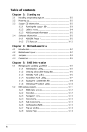
... description 1. CDs • Support CD • Recover PRO CD 4. AH2 barebone system with • ASUS motherboard • CPU fan and heatsink assembly • CompactFlash card reader • 3-in-1 storage card reader • PCI riser card • 250W power supply unit 2. ASUS Pundit P1 - Quick installation Guide x AH2 system package for the following items. If any of the...
... description 1. CDs • Support CD • Recover PRO CD 4. AH2 barebone system with • ASUS motherboard • CPU fan and heatsink assembly • CompactFlash card reader • 3-in-1 storage card reader • PCI riser card • 250W power supply unit 2. ASUS Pundit P1 - Quick installation Guide x AH2 system package for the following items. If any of the...

User Guide
Page 12
The ASUS Pundit P1-AH2 is an all-in a stylish casing and powered by the ASUS motherboard that supports the AMD® Athlon64, AMD® Athlon 64 FX, AMD® Sempron, or AMD® Athlon 64 X2 processor. The system comes in -one barebone system with a versatile home entertainment feature. Thank you for choosing the ASUS Pundit P1-AH2! The system...
The ASUS Pundit P1-AH2 is an all-in a stylish casing and powered by the ASUS motherboard that supports the AMD® Athlon64, AMD® Athlon 64 FX, AMD® Sempron, or AMD® Athlon 64 X2 processor. The system comes in -one barebone system with a versatile home entertainment feature. Thank you for choosing the ASUS Pundit P1-AH2! The system...
User Guide
Page 16
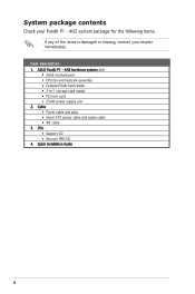
DIMM sockets 2. CPU fan and heatsink assembly 4. Power supply unit 8. ASUS motherboard inch hard disk drive cage 6. CPU socket 3. Proceed to the motherboard PCI slot) 1-6 Chapter 1: System introduction Front penel cover 7. PCI card riser bracket (connected to Chapter 2 for your reference. 1.4 Internal components The illustration below is the ...
DIMM sockets 2. CPU fan and heatsink assembly 4. Power supply unit 8. ASUS motherboard inch hard disk drive cage 6. CPU socket 3. Proceed to the motherboard PCI slot) 1-6 Chapter 1: System introduction Front penel cover 7. PCI card riser bracket (connected to Chapter 2 for your reference. 1.4 Internal components The illustration below is the ...
User Guide
Page 18
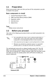
... components you uninstall any system component. SB_PWR ON OFF Standby Powered R Power Off Onboard LED 2-2 Chapter 2: Basic installation DDR2 Dual Inline Memory Module (DIMM) 3. The motherboard comes with the component. Basic components to avoid touching the ICs on a grounded antistatic pad or in the bag that came with an onboard standby...
... components you uninstall any system component. SB_PWR ON OFF Standby Powered R Power Off Onboard LED 2-2 Chapter 2: Basic installation DDR2 Dual Inline Memory Module (DIMM) 3. The motherboard comes with the component. Basic components to avoid touching the ICs on a grounded antistatic pad or in the bag that came with an onboard standby...
User Guide
Page 22
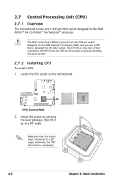
2.7 Central Processing Unit (CPU) 2.7.1 Overview The motherboard comes with a 940-pin AM2 socket designed for the AMD Opteron™ processor. The CPU fits in completely. 2-6 Chapter 2: Basic installation DO NOT force ...; processor. Make sure you use a CPU that the socket lever is designed for the AM2 socket. R CPU Socket AM2 2. Locate the CPU socket on the motherboard. otherwise, the CPU will not fit in only one correct orientation. Unlock the socket by pressing the lever sideways, then lift it up to prevent...
2.7 Central Processing Unit (CPU) 2.7.1 Overview The motherboard comes with a 940-pin AM2 socket designed for the AMD Opteron™ processor. The CPU fits in completely. 2-6 Chapter 2: Basic installation DO NOT force ...; processor. Make sure you use a CPU that the socket lever is designed for the AM2 socket. R CPU Socket AM2 2. Locate the CPU socket on the motherboard. otherwise, the CPU will not fit in only one correct orientation. Unlock the socket by pressing the lever sideways, then lift it up to prevent...
User Guide
Page 24
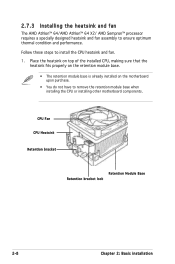
... installed CPU, making sure that the heatsink fits properly on the retention module base. • The retention module base is already installed on the motherboard upon purchase. • You do not have to remove the retention module base when installing the CPU or installing other...
... installed CPU, making sure that the heatsink fits properly on the retention module base. • The retention module base is already installed on the motherboard upon purchase. • You do not have to remove the retention module base when installing the CPU or installing other...

User Guide
Page 25
Hardware monitoring errors can occur if you cannot snap the retention bracket in place. 4. Push down the retention bracket lock on the motherboard labeled CPU_FAN. A clicking sound denotes that the fan and heatsink assembly perfectly fits the retention mechanism module base, otherwise you fail to plug this ... in place, connect the CPU fan cable to the connector on the retention mechanism to secure the heatsink and fan to the retention module base. ASUS Pundit P1-AH2 2-9 2. Align the other end of the retention bracket to connect the CPU fan connector!
Hardware monitoring errors can occur if you cannot snap the retention bracket in place. 4. Push down the retention bracket lock on the motherboard labeled CPU_FAN. A clicking sound denotes that the fan and heatsink assembly perfectly fits the retention mechanism module base, otherwise you fail to plug this ... in place, connect the CPU fan cable to the connector on the retention mechanism to secure the heatsink and fan to the retention module base. ASUS Pundit P1-AH2 2-9 2. Align the other end of the retention bracket to connect the CPU fan connector!
User Guide
Page 26
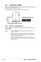
... memory modules. For optimum compatibility, we recommend that you obtain memory modules from the same vendor. 2-8 Chapter 2: Basic installation Visit the ASUS website for details. 2.8 Installing a DIMM The system motherboard comes with the same CAS latency. The following figure illustrates the location of the sockets: R DIMM_B1 DIMM_A1 128 Pins 240-pin...
... memory modules. For optimum compatibility, we recommend that you obtain memory modules from the same vendor. 2-8 Chapter 2: Basic installation Visit the ASUS website for details. 2.8 Installing a DIMM The system motherboard comes with the same CAS latency. The following figure illustrates the location of the sockets: R DIMM_B1 DIMM_A1 128 Pins 240-pin...
User Guide
Page 29
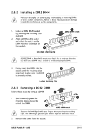
ASUS Pundit P1-AH2 2-11 Locked Retaining Clip 2.8.3 Removing a DDR2 DIMM Follow these steps to avoid damaging the DIMM. 3. DO NOT force a DIMM into the 3 socket until the retaining ... 2 DDR2 DIMM notch 1 A DDR2 DIMM is properly seated. Firmly insert the DIMM into a socket to remove a DIMM. 2 1. 2.8.2 Installing a DDR2 DIMM Make sure to both the motherboard and the components. 1. Unlock a DDR2 DIMM socket by pressing the retaining clips outward. 2. Simultaneously press the retaining clips outward to unlock the DIMM. 1 1 DDR2 DIMM...
ASUS Pundit P1-AH2 2-11 Locked Retaining Clip 2.8.3 Removing a DDR2 DIMM Follow these steps to avoid damaging the DIMM. 3. DO NOT force a DIMM into the 3 socket until the retaining ... 2 DDR2 DIMM notch 1 A DDR2 DIMM is properly seated. Firmly insert the DIMM into a socket to remove a DIMM. 2 1. 2.8.2 Installing a DDR2 DIMM Make sure to both the motherboard and the components. 1. Unlock a DDR2 DIMM socket by pressing the retaining clips outward. 2. Simultaneously press the retaining clips outward to unlock the DIMM. 1 1 DDR2 DIMM...
User Guide
Page 30
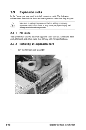
... cause you may need to unplug the power cord before adding or removing expansion cards. 2.9 Expansion slots In the future, you physical injury and damage motherboard components. 2.9.1 PCI slots This system has two PCI slot that supports cards such as a LAN card, SCSI card, USB card, and other cards that they...
... cause you may need to unplug the power cord before adding or removing expansion cards. 2.9 Expansion slots In the future, you physical injury and damage motherboard components. 2.9.1 PCI slots This system has two PCI slot that supports cards such as a LAN card, SCSI card, USB card, and other cards that they...
User Guide
Page 31
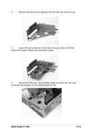
Make sure that you intend to the slot, then press the card firmly until it fits in place. Insert the card connector to use. 3. Remove the metal cover opposite the slot that the riser card connector sits properly on the motherboard PCI slot. Reinstall the PCI riser card assembly. Secure the card with a screw. 4. 2. ASUS Pundit P1-AH2 2-13
Make sure that you intend to the slot, then press the card firmly until it fits in place. Insert the card connector to use. 3. Remove the metal cover opposite the slot that the riser card connector sits properly on the motherboard PCI slot. Reinstall the PCI riser card assembly. Secure the card with a screw. 4. 2. ASUS Pundit P1-AH2 2-13

User Guide
Page 36
Because motherboard settings and hardware options vary, use the setup procedures presented in this chapter for different operating system versions. • The contents of your OS documentation ... several utility drivers that enhance the system features. • Screen display and driver options may not be the same for general reference only. Visit the ASUS website for more information. 3.2 Powering up 3.1 Installing an operating system The barebone system supports Windows® 2000/XP operating systems (OS). Refer to change at...
Because motherboard settings and hardware options vary, use the setup procedures presented in this chapter for different operating system versions. • The contents of your OS documentation ... several utility drivers that enhance the system features. • Screen display and driver options may not be the same for general reference only. Visit the ASUS website for more information. 3.2 Powering up 3.1 Installing an operating system The barebone system supports Windows® 2000/XP operating systems (OS). Refer to change at...
User Guide
Page 37
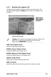
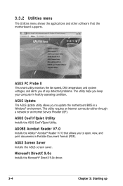
... is NOT enabled in your computer. Realtek Audio Driver Allows you to run the CD. Click an icon to display support CD/motherboard information Click an item to install If Autorun is enabled in your optical drive. Double-click the ASSETUP.EXE to install the Realtek...Installs the AMD CoolʼnʼQuiet driver. USB 2.0 Driver Installs the USB 2.0 driver file that came with the utility for details. ASUS Pundit P1-AH2 3-3 NVIDIA GeForce 61X0 Display Driver Installs the NVIDIA GeForce 61X0 display driver. 3.3.1 Running the support CD To begin using the support CD, place...
... is NOT enabled in your computer. Realtek Audio Driver Allows you to run the CD. Click an icon to display support CD/motherboard information Click an item to install If Autorun is enabled in your optical drive. Double-click the ASSETUP.EXE to install the Realtek...Installs the AMD CoolʼnʼQuiet driver. USB 2.0 Driver Installs the USB 2.0 driver file that came with the utility for details. ASUS Pundit P1-AH2 3-3 NVIDIA GeForce 61X0 Display Driver Installs the NVIDIA GeForce 61X0 display driver. 3.3.1 Running the support CD To begin using the support CD, place...
User Guide
Page 38
...® environment. ADOBE Acrobat Reader V7.0 Installs the Adobe® Acrobat® Reader V7.0 that the motherboard supports. ASUS Screen Saver Installs the ASUS screen saver. 3.3.2 Utilities menu The Utilities menu shows the applications and other software that allows you to update the... motherboard BIOS in healthy operating condition. ASUS CoolʼnʼQuiet Utility Installs the ASUS CoolʼnʼQuiet Utility. This utility requires an Internet connection either through a network...
...® environment. ADOBE Acrobat Reader V7.0 Installs the Adobe® Acrobat® Reader V7.0 that the motherboard supports. ASUS Screen Saver Installs the ASUS screen saver. 3.3.2 Utilities menu The Utilities menu shows the applications and other software that allows you to update the... motherboard BIOS in healthy operating condition. ASUS CoolʼnʼQuiet Utility Installs the ASUS CoolʼnʼQuiet Utility. This utility requires an Internet connection either through a network...
User Guide
Page 45
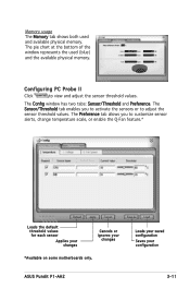
... your changes Cancels or ignores your configuration 3-11 The Sensor/Threshold tab enables you to adjust the sensor threshold values. ASUS Pundit P1-AH2 Loads your saved configuration Saves your changes *Available on some motherboards only. The pie chart at the bottom of the window represents the used and available physical memory. Configuring PC Probe...
... your changes Cancels or ignores your configuration 3-11 The Sensor/Threshold tab enables you to adjust the sensor threshold values. ASUS Pundit P1-AH2 Loads your saved configuration Saves your changes *Available on some motherboards only. The pie chart at the bottom of the window represents the used and available physical memory. Configuring PC Probe...
User Guide
Page 50
Motherboard info Chapter 4 This chapter gives information about the motherboard that comes with the system. ASUS Pundit P1-AH2 This chapter includes the motherboard layout, jumper settings, and connector locations.
Motherboard info Chapter 4 This chapter gives information about the motherboard that comes with the system. ASUS Pundit P1-AH2 This chapter includes the motherboard layout, jumper settings, and connector locations.

User Guide
Page 51
This chapter provides technical information about the motherboard for future upgrades or system reconfiguration. 4.2 Motherboard layout USB56 BUZ1 USBPW56 SB_PWR1 LED_CON1 4Mb BIOS CR2032 3V Lithium Cell CMOS Power CLRTC RSTCON1 CF_CON MCP51 SMSC 2227 PRI_IDE SATA1 SATA2 USBPW34 KBMS1 ...) DDR2 DIMM_A1(64 bit,240-pin module) 13.3inches 3IN1_CON ADP3186 SPDIF_OUT IE1394_1 PWR SW1 IE 1394_2 USB1 2 FRONT_AUD1 ATX12V1 CPU_FAN1 USBPW12 10.4inches 4-2 Chapter 4: Motherboard info 4.1 Introduction The Pundit P1-AH2 barebone system comes with an ASUS motherboard.
This chapter provides technical information about the motherboard for future upgrades or system reconfiguration. 4.2 Motherboard layout USB56 BUZ1 USBPW56 SB_PWR1 LED_CON1 4Mb BIOS CR2032 3V Lithium Cell CMOS Power CLRTC RSTCON1 CF_CON MCP51 SMSC 2227 PRI_IDE SATA1 SATA2 USBPW34 KBMS1 ...) DDR2 DIMM_A1(64 bit,240-pin module) 13.3inches 3IN1_CON ADP3186 SPDIF_OUT IE1394_1 PWR SW1 IE 1394_2 USB1 2 FRONT_AUD1 ATX12V1 CPU_FAN1 USBPW12 10.4inches 4-2 Chapter 4: Motherboard info 4.1 Introduction The Pundit P1-AH2 barebone system comes with an ASUS motherboard.
User Guide
Page 53
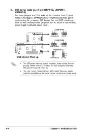
... device wake-up . • The total current consumed must NOT exceed the power supply capability (+5VSB) whether under normal condition or in sleep mode. 4-4 Chapter 4: Motherboard info Set to +5VSB to wake up the computer from S3 and S4 sleep modes (no power to wake up from S1 sleep mode (CPU...
... device wake-up . • The total current consumed must NOT exceed the power supply capability (+5VSB) whether under normal condition or in sleep mode. 4-4 Chapter 4: Motherboard info Set to +5VSB to wake up the computer from S3 and S4 sleep modes (no power to wake up from S1 sleep mode (CPU...