
User Guide
Page 1
Motherboard PRIME Z370-A Series
Motherboard PRIME Z370-A Series

User Guide
Page 13
...bit ATX Form Factor, 12"x 9.6" (30.5cm x 24.4cm) • Specifications are subject to change without notice. • Visit the ASUS website for ASUS ThunderboltEX series support 1 x TPM connector 1 x COM connector 1 x 24-pin EATX Power connector 1 x 8-pin EATX 12V Power connector 1 x ... 3, F11 EZ Tuning Wizard, F6 Qfan Control, F3 My Favorites, Last Modified log, F12 PrintScreen, and ASUS DRAM SPD (Serial Presence Detect) memory information. PRIME Z370-A specifications summary Internal I/O connectors BIOS Manageability Support DVD contents Operating system support Form factor 2 x USB 3.1...
...bit ATX Form Factor, 12"x 9.6" (30.5cm x 24.4cm) • Specifications are subject to change without notice. • Visit the ASUS website for ASUS ThunderboltEX series support 1 x TPM connector 1 x COM connector 1 x 24-pin EATX Power connector 1 x 8-pin EATX 12V Power connector 1 x ... 3, F11 EZ Tuning Wizard, F6 Qfan Control, F3 My Favorites, Last Modified log, F12 PrintScreen, and ASUS DRAM SPD (Serial Presence Detect) memory information. PRIME Z370-A specifications summary Internal I/O connectors BIOS Manageability Support DVD contents Operating system support Form factor 2 x USB 3.1...
User Guide
Page 17
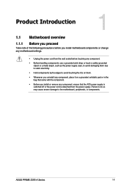
...; Whenever you uninstall any component, place it on them due to static electricity. • Hold components by the edges to the motherboard, peripherals, or components. ASUS PRIME Z370-A Series 1-1 Failure to do so may cause severe damage to avoid touching the ICs on a grounded antistatic pad or in the bag that came with the...
...; Whenever you uninstall any component, place it on them due to static electricity. • Hold components by the edges to the motherboard, peripherals, or components. ASUS PRIME Z370-A Series 1-1 Failure to do so may cause severe damage to avoid touching the ICs on a grounded antistatic pad or in the bag that came with the...
User Guide
Page 19
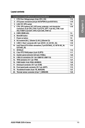
... Mount 12. Thermal sensor connector (2-pin T_SENSOR) Page 1-12 1-19 1-4 1-18 1-5 1-10 1-9 1-22 1-16 1-14 1-12 1-11 1-20 1-17 1-21 1-23 1-24 1-15 1-21 1-24 ASUS PRIME Z370-A Series 1-3 Chapter 1 Layout contents Connectors/Jumpers/Buttons and switches/Slots 1. Power-on button 8. USB 2.0 connectors (10-1 pin USB910; RGB header (4-pin RGB_HEADER) 17.
... Mount 12. Thermal sensor connector (2-pin T_SENSOR) Page 1-12 1-19 1-4 1-18 1-5 1-10 1-9 1-22 1-16 1-14 1-12 1-11 1-20 1-17 1-21 1-23 1-24 1-15 1-21 1-24 ASUS PRIME Z370-A Series 1-3 Chapter 1 Layout contents Connectors/Jumpers/Buttons and switches/Slots 1. Power-on button 8. USB 2.0 connectors (10-1 pin USB910; RGB header (4-pin RGB_HEADER) 17.
User Guide
Page 21
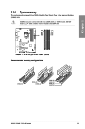
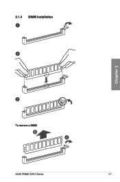
DO NOT install a DDR, DDR2, or DDR3 memory module to the DDR4 slot. Recommended memory configurations ASUS PRIME Z370-A Series 1-5 Chapter 1 1.1.4 System memory The motherboard comes with four DDR4 (Double Data Rate 4) Dual Inline Memory Modules (DIMM) slots. A DDR4 module is notched differently from a DDR, DDR2, or DDR3 module.
DO NOT install a DDR, DDR2, or DDR3 memory module to the DDR4 slot. Recommended memory configurations ASUS PRIME Z370-A Series 1-5 Chapter 1 1.1.4 System memory The motherboard comes with four DDR4 (Double Data Rate 4) Dual Inline Memory Modules (DIMM) slots. A DDR4 module is notched differently from a DDR, DDR2, or DDR3 module.
User Guide
Page 23
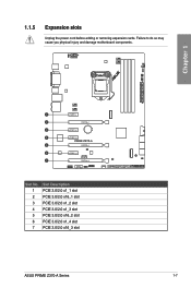
Failure to do so may cause you physical injury and damage motherboard components. 1.1.5 Expansion slots Unplug the power cord before adding or removing expansion cards. Chapter 1 Slot No. 1 2 3 4 5 6 7 Slot Description PCIE 3.0/2.0 x1_1 slot PCIE 3.0/2.0 x16_1 slot PCIE 3.0/2.0 x1_2 slot PCIE 3.0/2.0 x1_3 slot PCIE 3.0/2.0 x16_2 slot PCIE 3.0/2.0 x1_4 slot PCIE 3.0/2.0 x16_3 slot ASUS PRIME Z370-A Series 1-7
Failure to do so may cause you physical injury and damage motherboard components. 1.1.5 Expansion slots Unplug the power cord before adding or removing expansion cards. Chapter 1 Slot No. 1 2 3 4 5 6 7 Slot Description PCIE 3.0/2.0 x1_1 slot PCIE 3.0/2.0 x16_1 slot PCIE 3.0/2.0 x1_2 slot PCIE 3.0/2.0 x1_3 slot PCIE 3.0/2.0 x16_2 slot PCIE 3.0/2.0 x1_4 slot PCIE 3.0/2.0 x16_3 slot ASUS PRIME Z370-A Series 1-7
User Guide
Page 25
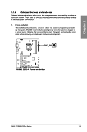
... who continually change settings to fine-tune performance when working on button that allows you to a power source indicating that you to enhance system performance. 1. ASUS PRIME Z370-A Series 1-9 This is plugged to power up or wake up the system. Chapter 1 1.1.6 Onboard buttons and switches Onboard buttons and switches allow you should shut down...
... who continually change settings to fine-tune performance when working on button that allows you to a power source indicating that you to enhance system performance. 1. ASUS PRIME Z370-A Series 1-9 This is plugged to power up or wake up the system. Chapter 1 1.1.6 Onboard buttons and switches Onboard buttons and switches allow you should shut down...

User Guide
Page 27
... the computer. 4. For system failure due to clear the Real Time Clock (RTC) RAM in CMOS, which include system setup information such as system passwords. ASUS PRIME Z370-A Series 1-11 1.1.7 Jumpers and holes 1. You can automatically reset parameter settings to default values. • Due to the chipset behavior, AC power off and turn on...
... the computer. 4. For system failure due to clear the Real Time Clock (RTC) RAM in CMOS, which include system setup information such as system passwords. ASUS PRIME Z370-A Series 1-11 1.1.7 Jumpers and holes 1. You can automatically reset parameter settings to default values. • Due to the chipset behavior, AC power off and turn on...
User Guide
Page 29
... vary from case to indicate that you should shut down the system and unplug the power cable before removing or plugging in soft-off mode. ASUS PRIME Z370-A Series 1-13
... vary from case to indicate that you should shut down the system and unplug the power cable before removing or plugging in soft-off mode. ASUS PRIME Z370-A Series 1-13

User Guide
Page 31
We recommend that supports HD Audio. ASUS PRIME Z370-A Series 1-15 Front panel audio connector (10-1 pin AAFP) This connector is for a chassis-mounted front panel audio I /O module cable to avail of the front panel audio I /O module that you connect a high-definition front panel audio module to this connector to this connector. Connect one end of the motherboard's high-definition audio capability. Chapter 1 2.
We recommend that supports HD Audio. ASUS PRIME Z370-A Series 1-15 Front panel audio connector (10-1 pin AAFP) This connector is for a chassis-mounted front panel audio I /O module cable to avail of the front panel audio I /O module that you connect a high-definition front panel audio module to this connector to this connector. Connect one end of the motherboard's high-definition audio capability. Chapter 1 2.
User Guide
Page 33
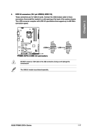
USB1112) These connectors are for USB 2.0 ports. DO NOT connect a 1394 cable to 480 Mb/s connection speed. This USB connector complies with USB 2.0 specification that supports up to the USB connectors. ASUS PRIME Z370-A Series 1-17 The USB 2.0 module is purchased separately. Chapter 1 4. Connect the USB module cable to these connectors, then install the module to a slot opening at the back of the system chassis. Doing so will damage the motherboard! USB 2.0 connectors (10-1 pin USB910;
USB1112) These connectors are for USB 2.0 ports. DO NOT connect a 1394 cable to 480 Mb/s connection speed. This USB connector complies with USB 2.0 specification that supports up to the USB connectors. ASUS PRIME Z370-A Series 1-17 The USB 2.0 module is purchased separately. Chapter 1 4. Connect the USB module cable to these connectors, then install the module to a slot opening at the back of the system chassis. Doing so will damage the motherboard! USB 2.0 connectors (10-1 pin USB910;
User Guide
Page 35
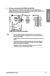
... to use two or more high-end PCI Express x16 cards, use a PSU with a higher power output when configuring a system with more power-consuming devices. ASUS PRIME Z370-A Series 1-19 Otherwise, the system will not boot. • We recommend that complies with 1000W power or above to connect the 8-pin EATX12V power plug. Chapter...
... to use two or more high-end PCI Express x16 cards, use a PSU with a higher power output when configuring a system with more power-consuming devices. ASUS PRIME Z370-A Series 1-19 Otherwise, the system will not boot. • We recommend that complies with 1000W power or above to connect the 8-pin EATX12V power plug. Chapter...

User Guide
Page 37
Thunderbolt header (5-pin TB_HEADER) This connector is purchased separately. 9. The add-on Thunderbolt I /O card and Thunderbolt cables are purchased separately. ASUS PRIME Z370-A Series 1-21 A TPM system also helps enhance network security, protect digital identities, and ensures platform integrity. Chapter 1 The TPM module is for the add-on Thunderbolt I /O ...
Thunderbolt header (5-pin TB_HEADER) This connector is purchased separately. 9. The add-on Thunderbolt I /O card and Thunderbolt cables are purchased separately. ASUS PRIME Z370-A Series 1-21 A TPM system also helps enhance network security, protect digital identities, and ensures platform integrity. Chapter 1 The TPM module is for the add-on Thunderbolt I /O ...
User Guide
Page 39
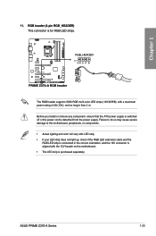
RGB header (4-pin RGB_HEADER) This connector is detached from the power supply. ASUS PRIME Z370-A Series 1-23 Before you install or remove any component, ensure that the ATX power supply is switched off or the power cord is for RGB LED ...
RGB header (4-pin RGB_HEADER) This connector is detached from the power supply. ASUS PRIME Z370-A Series 1-23 Before you install or remove any component, ensure that the ATX power supply is switched off or the power cord is for RGB LED ...

User Guide
Page 41
The motherboard layout may vary with models, but the installation steps are for reference only. Chapter 2: Basic Installation Basic Installation 2.1 Building your PC system 2 2.1.1 The diagrams in this section are the same for all models. CPU installation Ensure that you install the correct CPU designed for LGA1155 and LGA1156 sockets on the LGA1151 socket. Chapter 2 Top of CPU Bottom of CPU ASUS PRIME Z370-A Series Bottom of CPU 2-1 DO NOT install a CPU designed for LGA1151 socket only.
The motherboard layout may vary with models, but the installation steps are for reference only. Chapter 2: Basic Installation Basic Installation 2.1 Building your PC system 2 2.1.1 The diagrams in this section are the same for all models. CPU installation Ensure that you install the correct CPU designed for LGA1155 and LGA1156 sockets on the LGA1151 socket. Chapter 2 Top of CPU Bottom of CPU ASUS PRIME Z370-A Series Bottom of CPU 2-1 DO NOT install a CPU designed for LGA1151 socket only.
User Guide
Page 43
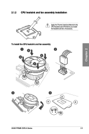
2.1.2 CPU heatsink and fan assembly installation Apply the Thermal Interface Material to the CPU heatsink and CPU before you install the heatsink and fan, if necessary. To install the CPU heatsink and fan assembly Chapter 2 ASUS PRIME Z370-A Series 2-3
2.1.2 CPU heatsink and fan assembly installation Apply the Thermal Interface Material to the CPU heatsink and CPU before you install the heatsink and fan, if necessary. To install the CPU heatsink and fan assembly Chapter 2 ASUS PRIME Z370-A Series 2-3
User Guide
Page 45
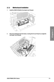
Chapter 2 ASUS PRIME Z370-A Series 2-5 2.1.3 Motherboard installation 1. Install the ASUS Q-Shield to the chassis' rear I /O panel. 2. Place the motherboard into the chassis, ensuring that its rear I/O ports are aligned to the chassis rear I /O panel.
Chapter 2 ASUS PRIME Z370-A Series 2-5 2.1.3 Motherboard installation 1. Install the ASUS Q-Shield to the chassis' rear I /O panel. 2. Place the motherboard into the chassis, ensuring that its rear I/O ports are aligned to the chassis rear I /O panel.
User Guide
Page 47
2.1.4 DIMM installation Chapter 2 To remove a DIMM ASUS PRIME Z370-A Series 2-7
2.1.4 DIMM installation Chapter 2 To remove a DIMM ASUS PRIME Z370-A Series 2-7
User Guide
Page 51
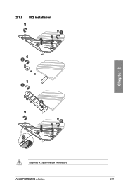
ASUS PRIME Z370-A Series 2-11 2.1.9 M.2 installation 1 2 3 Chapter 2 5 4 8 7 6 Supported M.2 type varies per motherboard.
ASUS PRIME Z370-A Series 2-11 2.1.9 M.2 installation 1 2 3 Chapter 2 5 4 8 7 6 Supported M.2 type varies per motherboard.
User Guide
Page 53
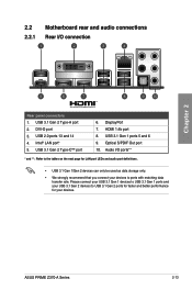
... 2 Type-C™ port 6. Please connect your USB 3.1 Gen 1 devices to USB 3.1 Gen 1 ports and your USB 3.1 Gen 2 devices to ports with matching data transfer rate. ASUS PRIME Z370-A Series 2-13 Intel® LAN port* 5. DVI-D port 3. DisplayPort 7. USB 3.1 Gen 2 Type-A port 2. USB 2.0 ports 13 and 14 4. Audio I /O connection Rear panel connectors 1. Optical S/PDIF Out...
... 2 Type-C™ port 6. Please connect your USB 3.1 Gen 1 devices to USB 3.1 Gen 1 ports and your USB 3.1 Gen 2 devices to ports with matching data transfer rate. ASUS PRIME Z370-A Series 2-13 Intel® LAN port* 5. DVI-D port 3. DisplayPort 7. USB 3.1 Gen 2 Type-A port 2. USB 2.0 ports 13 and 14 4. Audio I /O connection Rear panel connectors 1. Optical S/PDIF Out...
