Motherboard Pin Definition.English
Page 3
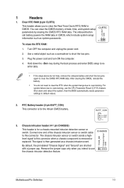
... component is for the lithium CMOS battery. Connect one end of date, time, and system setup parameters by erasing the CMOS RTC RAM data. Clear RTC RAM (2-pin CLRTC) This header allows you intend to overclocking. BATT_CON VBAT GND PIN 1 3. Plug the power cord and turn ON the... CMOS, which include system setup information such as system passwords. +3V_BAT GND CLRTC PIN 1 To erase the RTC RAM: 1. The onboard button cell battery powers the RAM data in CMOS. For system failure due to short the two pins. 3. The signal is for a chassis-mounted intrusion...
... component is for the lithium CMOS battery. Connect one end of date, time, and system setup parameters by erasing the CMOS RTC RAM data. Clear RTC RAM (2-pin CLRTC) This header allows you intend to overclocking. BATT_CON VBAT GND PIN 1 3. Plug the power cord and turn ON the... CMOS, which include system setup information such as system passwords. +3V_BAT GND CLRTC PIN 1 To erase the RTC RAM: 1. The onboard button cell battery powers the RAM data in CMOS. For system failure due to short the two pins. 3. The signal is for a chassis-mounted intrusion...
Motherboard Pin Definition.English
Page 4
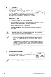
... during the boot process and enter BIOS setup to pins 1-2. 3. You can automatically reset parameter settings to clear the CMOS RTC RAM data. To erase the RTC RAM: CLRTC 12 23 Normal (Default) Clear RTC 1. Turn OFF the computer and unplug the power cord. 2. Removing the cap ... 1-2 (default) to disable it . 1-4 Motherboard Pin Definition Keep the cap on CLRTC jumper default position. The onboard button cell battery powers the RAM data in CMOS. DIS_ME 12 23 Normal (Default) Disable ME Disable the Intel® ME function before updating it . Hold down and reboot the...
... during the boot process and enter BIOS setup to pins 1-2. 3. You can automatically reset parameter settings to clear the CMOS RTC RAM data. To erase the RTC RAM: CLRTC 12 23 Normal (Default) Clear RTC 1. Turn OFF the computer and unplug the power cord. 2. Removing the cap ... 1-2 (default) to disable it . 1-4 Motherboard Pin Definition Keep the cap on CLRTC jumper default position. The onboard button cell battery powers the RAM data in CMOS. DIS_ME 12 23 Normal (Default) Disable ME Disable the Intel® ME function before updating it . Hold down and reboot the...

Users manual ENGLISH
Page 11
...(PSU) that you are uncertain about the minimum power supply requirement for details. Chapter 1: Product introduction 1-2 Intel® H270 Serial ATA 6.0 Gb/s connector (7-pin SATA6G_1~6) 8. Mono out header (2-pin MONO_OUT) 14. Clear RTC RAM (2-pin CLRTC) 9. 1.2.1 Layout contents Connectors/Jumpers/Slots/LED 1. Intel® LGA1151 CPU socket 4. The system may ..., we recommend that complies with more power-consuming devices or when you intend to the Recommended Power Supply Wattage Calculator at http://support.asus.com/PowerSupplyCalculator/PSCalculator. DDR4 DIMM slots 5.
...(PSU) that you are uncertain about the minimum power supply requirement for details. Chapter 1: Product introduction 1-2 Intel® H270 Serial ATA 6.0 Gb/s connector (7-pin SATA6G_1~6) 8. Mono out header (2-pin MONO_OUT) 14. Clear RTC RAM (2-pin CLRTC) 9. 1.2.1 Layout contents Connectors/Jumpers/Slots/LED 1. Intel® LGA1151 CPU socket 4. The system may ..., we recommend that complies with more power-consuming devices or when you intend to the Recommended Power Supply Wattage Calculator at http://support.asus.com/PowerSupplyCalculator/PSCalculator. DDR4 DIMM slots 5.

Users manual ENGLISH
Page 13
...have updated your motherboard drivers and BIOS to the latest version from ASUS support website. Intel® H270 Serial ATA 6.0Gb/s connectors (7-pin SATA6G_1~6) These connectors connect to clear the CMOS RTC RAM data of the system setup information such as a screwdriver to install... cables. Before using 7th Generation Intel® processors. Chapter 1: Product introduction 1-4 M.2_1(SOCKET3) 2280 2260 2242 M.2_2(SOCKET3) PRIME Z270-P 2280 2260 2242 PRIME Z270-P M.2(SOCKET3)s • M.2_1/2 Socket 3 support M Key and type 2242/2260/2280 storage devices. • The M....
...have updated your motherboard drivers and BIOS to the latest version from ASUS support website. Intel® H270 Serial ATA 6.0Gb/s connectors (7-pin SATA6G_1~6) These connectors connect to clear the CMOS RTC RAM data of the system setup information such as a screwdriver to install... cables. Before using 7th Generation Intel® processors. Chapter 1: Product introduction 1-4 M.2_1(SOCKET3) 2280 2260 2242 M.2_2(SOCKET3) PRIME Z270-P 2280 2260 2242 PRIME Z270-P M.2(SOCKET3)s • M.2_1/2 Socket 3 support M Key and type 2242/2260/2280 storage devices. • The M....
Users manual ENGLISH
Page 26
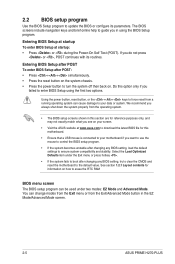
...Setup after POST To enter BIOS Setup after POST: • Press ++ simultaneously. • Press the reset button on how to erase the RTC RAM BIOS menu screen The BIOS setup program can cause damage to update the BIOS or configure its routines. You can change modes from the Exit...BIOS file for this motherboard. • Ensure that a USB mouse is connected to your motherboard if you in the EZ Mode/Advanced Mode screen. 2-5 ASUS PRIME H270-PLUS Using the power button, reset button, or the ++ keys to force reset from the operating system. • The BIOS setup screens shown in this...
...Setup after POST To enter BIOS Setup after POST: • Press ++ simultaneously. • Press the reset button on how to erase the RTC RAM BIOS menu screen The BIOS setup program can cause damage to update the BIOS or configure its routines. You can change modes from the Exit...BIOS file for this motherboard. • Ensure that a USB mouse is connected to your motherboard if you in the EZ Mode/Advanced Mode screen. 2-5 ASUS PRIME H270-PLUS Using the power button, reset button, or the ++ keys to force reset from the operating system. • The BIOS setup screens shown in this...


