
BIOSUpdateE-Manual English
Page 2
... is eager to infringe. SPECIFICATIONS AND INFORMATION CONTAINED IN THIS MANUAL ARE FURNISHED FOR INFORMATIONAL USE ONLY, AND ARE SUBJECT TO CHANGE AT ANY TIME WITHOUT NOTICE, AND SHOULD NOT BE CONSTRUED AS A COMMITMENT BY ASUS. ASUSTeK is licensed under the General Public License ("GPL"), under various Free Open Source Software licenses. No part of the product for...
... is eager to infringe. SPECIFICATIONS AND INFORMATION CONTAINED IN THIS MANUAL ARE FURNISHED FOR INFORMATIONAL USE ONLY, AND ARE SUBJECT TO CHANGE AT ANY TIME WITHOUT NOTICE, AND SHOULD NOT BE CONSTRUED AS A COMMITMENT BY ASUS. ASUSTeK is licensed under the General Public License ("GPL"), under various Free Open Source Software licenses. No part of the product for...
BIOSUpdateE-Manual English
Page 4
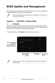
... motherboard BIOS file to a USB flash disk in case you need to restore the BIOS in updating and managing the BIOS setup program on the AI Suite 3 main menu bar. Chapter 1: UEFI BIOS - Graphics Mode 1.1 EZ Update EZ Update is a utility that you can also manually update the saved BIOS and select a boot logo when the system goes into POST. With this utlity, you to automatically update your motherboard's driver, software and firmware Click to find and select the BIOS from file...
... motherboard BIOS file to a USB flash disk in case you need to restore the BIOS in updating and managing the BIOS setup program on the AI Suite 3 main menu bar. Chapter 1: UEFI BIOS - Graphics Mode 1.1 EZ Update EZ Update is a utility that you can also manually update the saved BIOS and select a boot logo when the system goes into POST. With this utlity, you to automatically update your motherboard's driver, software and firmware Click to find and select the BIOS from file...
BIOSUpdateE-Manual English
Page 5
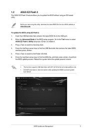
...; This function supports USB flash disks with FAT 32/16 format and single partition only. • DO NOT shut down or reset the system while updating the BIOS to update the BIOS without using EZ Flash 2: 1. 1.2 ASUS EZ Flash 2 The ASUS EZ Flash 2 feature allows you start using this utility, download the latest BIOS file from the ASUS website at www.asus.com To update the BIOS using an OS‑based utility. Press to switch to enable it...
...; This function supports USB flash disks with FAT 32/16 format and single partition only. • DO NOT shut down or reset the system while updating the BIOS to update the BIOS without using EZ Flash 2: 1. 1.2 ASUS EZ Flash 2 The ASUS EZ Flash 2 feature allows you start using this utility, download the latest BIOS file from the ASUS website at www.asus.com To update the BIOS using an OS‑based utility. Press to switch to enable it...
BIOSUpdateE-Manual English
Page 6
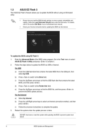
... system while updating the BIOS to the Drive field. Enter the Advanced Mode of the BIOS setup program. Follow the steps below to the USB port, then select by Internet. c) Follow the onscreen instructions to select an Internet connection method, and then press . Select the Load Optimized Defaults item under the Exit menu. Via USB a) Insert the USB flash disk that contains the latest BIOS file to update the BIOS via the...
... system while updating the BIOS to the Drive field. Enter the Advanced Mode of the BIOS setup program. Follow the steps below to the USB port, then select by Internet. c) Follow the onscreen instructions to select an Internet connection method, and then press . Select the Load Optimized Defaults item under the Exit menu. Via USB a) Insert the USB flash disk that contains the latest BIOS file to update the BIOS via the...

BIOSUpdateE-Manual English
Page 7
... load default BIOS values. BIOS Update and Management 7 1.4 ASUS CrashFree BIOS 3 The ASUS CrashFree BIOS 3 is an auto recovery tool that contains the updated BIOS file. • Before using the motherboard support DVD or a USB flash drive that allows you to restore the BIOS file when it fails or gets corrupted during the updating process. Doing so can restore a corrupted BIOS file using this utility, rename the BIOS file in the removable device. • The BIOS file in the support DVD may not be the latest version. Download...
... load default BIOS values. BIOS Update and Management 7 1.4 ASUS CrashFree BIOS 3 The ASUS CrashFree BIOS 3 is an auto recovery tool that contains the updated BIOS file. • Before using the motherboard support DVD or a USB flash drive that allows you to restore the BIOS file when it fails or gets corrupted during the updating process. Doing so can restore a corrupted BIOS file using this utility, rename the BIOS file in the removable device. • The BIOS file in the support DVD may not be the latest version. Download...
BIOSUpdateE-Manual English
Page 8
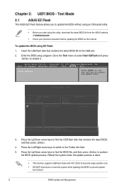
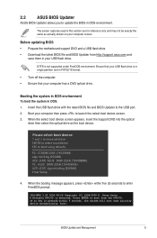
... the Tool menu to select Start EzFlash and press to select and update BIOS. 3. To update the BIOS using this utility, download the latest BIOS file from the ASUS website at www.asus.com • Check your Internet connection before updating the BIOS via the Internet. Text Mode 2.1 ASUS EZ Flash The ASUS EZ Flash feature allows you to the USB port. 2. Aptio Setup Utility - Press the Left/Right arrow keys to switch to prevent system boot failure! 8 BIOS Update and...
... the Tool menu to select Start EzFlash and press to select and update BIOS. 3. To update the BIOS using this utility, download the latest BIOS file from the ASUS website at www.asus.com • Check your Internet connection before updating the BIOS via the Internet. Text Mode 2.1 ASUS EZ Flash The ASUS EZ Flash feature allows you to the USB port. 2. Aptio Setup Utility - Press the Left/Right arrow keys to switch to prevent system boot failure! 8 BIOS Update and...
BIOSUpdateE-Manual English
Page 9
... shown on your computer then press to boot using defaults P2: ST3808110AS (76319MB) aigo miniking (250MB) UEFI: (FAT) ASUS DRW-2014L1T(4458MB) P1: ASUS DRW-2014L1T(4458MB) UEFI: (FAT) aigo miniking (250MB) Enter Setup 4. The screen captures used in your computer has a DVD optical drive. Before updating BIOS • Prepare the motherboard support DVD and a USB flash drive. • Download the latest BIOS file and BIOS Updater from the DVD/CD. NTFS is in single partition and...
... shown on your computer then press to boot using defaults P2: ST3808110AS (76319MB) aigo miniking (250MB) UEFI: (FAT) ASUS DRW-2014L1T(4458MB) P1: ASUS DRW-2014L1T(4458MB) UEFI: (FAT) aigo miniking (250MB) Enter Setup 4. The screen captures used in your computer has a DVD optical drive. Before updating BIOS • Prepare the motherboard support DVD and a USB flash drive. • Download the latest BIOS file and BIOS Updater from the DVD/CD. NTFS is in single partition and...

E11133MBPinDefinition English
Page 3
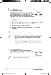
... and unplug the power cord. 2. 1 Headers 1. Use a metal object such as a screwdriver to overclocking, use the chassis intrusion detection feature. For system failure due to short the two pins. 3. RTC Battery header (2-pin BATT_CON) This connector is then generated as system passwords. +3V_BAT GND CLRTC PIN 1 To erase the RTC RAM: 1. Plug the power cord and turn ON the computer. 4. Shut down the key during the boot process and enter BIOS setup to reenter...
... and unplug the power cord. 2. 1 Headers 1. Use a metal object such as a screwdriver to overclocking, use the chassis intrusion detection feature. For system failure due to short the two pins. 3. RTC Battery header (2-pin BATT_CON) This connector is then generated as system passwords. +3V_BAT GND CLRTC PIN 1 To erase the RTC RAM: 1. Plug the power cord and turn ON the computer. 4. Shut down the key during the boot process and enter BIOS setup to reenter...
E11133MBPinDefinition English
Page 4
... 1. Set this jumper to pins 1-2 to enable (default) the Intel® ME function and to pins 2-3 to enable or disable the Intel® ME function. You can automatically reset parameter settings to overclocking. Shut down the key during the boot process and enter BIOS setup to clear the Real Time Clock (RTC) RAM in CMOS, which include system setup information such as system passwords. Keep the cap on CLRTC jumper default position. For system failure...
... 1. Set this jumper to pins 1-2 to enable (default) the Intel® ME function and to pins 2-3 to enable or disable the Intel® ME function. You can automatically reset parameter settings to overclocking. Shut down the key during the boot process and enter BIOS setup to clear the Real Time Clock (RTC) RAM in CMOS, which include system setup information such as system passwords. Keep the cap on CLRTC jumper default position. For system failure...

E11133MBPinDefinition English
Page 5
... (Default) for each USB port; 3. Display panel backlight power selector (3-pin BLKT_PWR_SEL) BLKT_PWR_SEL 12 23 Pins 1-2 (Default) 2-3 Setting 12V 19V 12V 19V (Default) 6. Set to +5VSB to wake 12 23 up from S1 sleep mode (CPU stopped, DRAM refreshed, system running in low power USBPWF mode) using the connected USB devices. Keyboard and USB device wake up (3-pin KB_USBPWB) This jumper allows you can supply at least 1A on the keyboard. otherwise, the system would not power up feature. USB device wake-up (3-pin USBPWF) Set these jumpers...
... (Default) for each USB port; 3. Display panel backlight power selector (3-pin BLKT_PWR_SEL) BLKT_PWR_SEL 12 23 Pins 1-2 (Default) 2-3 Setting 12V 19V 12V 19V (Default) 6. Set to +5VSB to wake 12 23 up from S1 sleep mode (CPU stopped, DRAM refreshed, system running in low power USBPWF mode) using the connected USB devices. Keyboard and USB device wake up (3-pin KB_USBPWB) This jumper allows you can supply at least 1A on the keyboard. otherwise, the system would not power up feature. USB device wake-up (3-pin USBPWF) Set these jumpers...

E11133MBPinDefinition English
Page 6
... an installed USB 3.0 module, you to a slot opening at the back of the system chassis. Connect the serial port module cable to this connector, then install the module to connect a USB 3.0 module for USB-chargeable devices, optimized power efficiency, and PIN 1 backward compatibility with USB 2.0 specifications and supports up to 480Mbps connection speed. These are not jumpers! Connect the USB module cable USB to this connector, then install the module to the fan connectors. 3 Internal Connectors 1. Do not place C jumper caps on the motherboard, ensuring...
... an installed USB 3.0 module, you to a slot opening at the back of the system chassis. Connect the serial port module cable to this connector, then install the module to connect a USB 3.0 module for USB-chargeable devices, optimized power efficiency, and PIN 1 backward compatibility with USB 2.0 specifications and supports up to 480Mbps connection speed. These are not jumpers! Connect the USB module cable USB to this connector, then install the module to the fan connectors. 3 Internal Connectors 1. Do not place C jumper caps on the motherboard, ensuring...

E11133MBPinDefinition English
Page 9
... EVEN_Lane1_P EVEN_Lane1_N EVEN_Lane0_P EVEN_Lane0_N EDID_GND LCD_VCC LCD_VCC LCD_VCC Enable LVDS in the BIOS setup if the LVDS output is for an LCD monitor that supports Low- Embedded DisplayPort (40- pin eDP) This connector is PIN 1 PIN 20 disabled by default. If you installed SATA hard disk drives, you can support one SATA Express device or two SATA devices. SATA6G You must install Windows® XP Service Pack 3 or later version before using Serial ATA hard disk drives. voltage Differential Signaling (LVDS) interface.
... EVEN_Lane1_P EVEN_Lane1_N EVEN_Lane0_P EVEN_Lane0_N EDID_GND LCD_VCC LCD_VCC LCD_VCC Enable LVDS in the BIOS setup if the LVDS output is for an LCD monitor that supports Low- Embedded DisplayPort (40- pin eDP) This connector is PIN 1 PIN 20 disabled by default. If you installed SATA hard disk drives, you can support one SATA Express device or two SATA devices. SATA6G You must install Windows® XP Service Pack 3 or later version before using Serial ATA hard disk drives. voltage Differential Signaling (LVDS) interface.

E11133MBPinDefinition English
Page 11
... system settings. HDD_LED+ HDD_LED- Connect the HDD Activity LED cable to hear system beeps and warnings. • ATX power button/soft-off mode depending on the system power, and blinks when the PIN 1 system is for the system power LED. Ground RESET NC PLED+ PLED- • Hard disk drive activity LED (2-pin +HDD_LED-) This 2-pin connector is for the system power button. System panel connector (20-5 pin PANEL) This connector supports several chassis-mounted functions. • System power LED (4-pin +PWR_LED-) PANEL +PWR_LED- Pressing the power button turns...
... system settings. HDD_LED+ HDD_LED- Connect the HDD Activity LED cable to hear system beeps and warnings. • ATX power button/soft-off mode depending on the system power, and blinks when the PIN 1 system is for the system power LED. Ground RESET NC PLED+ PLED- • Hard disk drive activity LED (2-pin +HDD_LED-) This 2-pin connector is for the system power button. System panel connector (20-5 pin PANEL) This connector supports several chassis-mounted functions. • System power LED (4-pin +PWR_LED-) PANEL +PWR_LED- Pressing the power button turns...

E11133MBPinDefinition English
Page 12
... power button. Connect the HDD Activity LED cable to this connector. GND Reset NC PLED+ PLED- The speaker allows you turn on the system power, and blinks when the system is for the chassis-mounted system warning speaker. The chassis intrusion sensor or switch sends a high-level signal to this connector. The signal is removed or replaced. RESET +PWR_LED- * Requires an ATX power supply This 2-pin connector is for a chassis-mounted intrusion detection sensor or switch. The HDD LED lights...
... power button. Connect the HDD Activity LED cable to this connector. GND Reset NC PLED+ PLED- The speaker allows you turn on the system power, and blinks when the system is for the chassis-mounted system warning speaker. The chassis intrusion sensor or switch sends a high-level signal to this connector. The signal is removed or replaced. RESET +PWR_LED- * Requires an ATX power supply This 2-pin connector is for a chassis-mounted intrusion detection sensor or switch. The HDD LED lights...
Users Manual English
Page 2
...SPECIFICATIONS AND INFORMATION CONTAINED IN THIS MANUAL ARE FURNISHED FOR INFORMATIONAL USE ONLY, AND ARE SUBJECT TO CHANGE AT ANY TIME WITHOUT NOTICE, AND SHOULD NOT BE CONSTRUED AS A COMMITMENT BY ASUS. to anyone in receipt of these licenses are used only for backup purposes, without any problems...by ASUS; ASUS ASSUMES NO RESPONSIBILITY OR LIABILITY FOR ANY ERRORS OR INACCURACIES THAT MAY APPEAR IN THIS MANUAL, INCLUDING THE PRODUCTS AND SOFTWARE DESCRIBED IN IT. Where the applicable license entitles you to the source code of such software and/or other Free Open Source Software ...
...SPECIFICATIONS AND INFORMATION CONTAINED IN THIS MANUAL ARE FURNISHED FOR INFORMATIONAL USE ONLY, AND ARE SUBJECT TO CHANGE AT ANY TIME WITHOUT NOTICE, AND SHOULD NOT BE CONSTRUED AS A COMMITMENT BY ASUS. to anyone in receipt of these licenses are used only for backup purposes, without any problems...by ASUS; ASUS ASSUMES NO RESPONSIBILITY OR LIABILITY FOR ANY ERRORS OR INACCURACIES THAT MAY APPEAR IN THIS MANUAL, INCLUDING THE PRODUCTS AND SOFTWARE DESCRIBED IN IT. Where the applicable license entitles you to the source code of such software and/or other Free Open Source Software ...
Users Manual English
Page 7
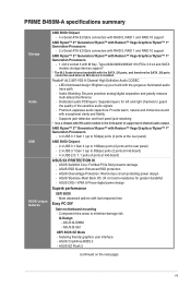
PRIME B450M-A specifications summary Storage Audio USB ASUS unique features AMD B450 Chipset - 4 x Serial ATA 6.0 Gb/s connectors with RAID 0, RAID 1 and RAID 10 support AMD Ryzen™ 2nd Generation/ Ryzen™ with Radeon™ Vega Graphics/ Ryzen™ 1st Generation Processors - 2 x Serial ATA 6.0 Gb/s connectors with RAID 0, RAID 1 and RAID 10 support AMD Ryzen™ 2nd Generation/ Ryzen™ with Radeon™ Vega Graphics/ Ryzen™ 1st Generation Processors - 1 x M.2 socket 3 with M Key, Type 2242/2260/2280/22110 (PCIe 3.0 x4 and SATA modes) storage devices support* * ...
PRIME B450M-A specifications summary Storage Audio USB ASUS unique features AMD B450 Chipset - 4 x Serial ATA 6.0 Gb/s connectors with RAID 0, RAID 1 and RAID 10 support AMD Ryzen™ 2nd Generation/ Ryzen™ with Radeon™ Vega Graphics/ Ryzen™ 1st Generation Processors - 2 x Serial ATA 6.0 Gb/s connectors with RAID 0, RAID 1 and RAID 10 support AMD Ryzen™ 2nd Generation/ Ryzen™ with Radeon™ Vega Graphics/ Ryzen™ 1st Generation Processors - 1 x M.2 socket 3 with M Key, Type 2242/2260/2280/22110 (PCIe 3.0 x4 and SATA modes) storage devices support* * ...
Users Manual English
Page 8
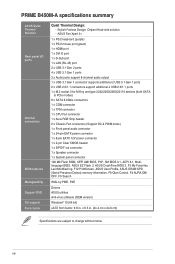
... connectors support additional 4 USB 2.0/1.1 ports 1 x M.2 socket 3 for M Key and type 2242/2260/2280/22110 devices (both SATA & PCIe modes) 6 x SATA 6.0Gb/s connectors 1 x COM connector 1 x TPM connector 1 x CPU Fan connector 1 x Aura RGB Strip header 2 x Chassis Fan connectors (Support DC & PWM mode) 1 x Front panel audio connector 1 x 24-pin EATX power connector 1 x 8-pin EATX 12V power connector 1 x 2-pin Clear CMOS header 1 x S/PDIF out connector 1 x Speaker connector 1 x System panel connector 128 Mb Flash ROM, UEFI AMI BIOS, PnP, SM BIOS 3.1, ACPI 6.1, Multilanguage BIOS, ASUS EZ Flash...
... connectors support additional 4 USB 2.0/1.1 ports 1 x M.2 socket 3 for M Key and type 2242/2260/2280/22110 devices (both SATA & PCIe modes) 6 x SATA 6.0Gb/s connectors 1 x COM connector 1 x TPM connector 1 x CPU Fan connector 1 x Aura RGB Strip header 2 x Chassis Fan connectors (Support DC & PWM mode) 1 x Front panel audio connector 1 x 24-pin EATX power connector 1 x 8-pin EATX 12V power connector 1 x 2-pin Clear CMOS header 1 x S/PDIF out connector 1 x Speaker connector 1 x System panel connector 128 Mb Flash ROM, UEFI AMI BIOS, PnP, SM BIOS 3.1, ACPI 6.1, Multilanguage BIOS, ASUS EZ Flash...

Users Manual English
Page 10
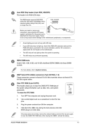
... power output when configuring a system with a minimum of maximum 1A (12 W) fan power. The system may become unstable or may damage the motherboard components. M.2(SOCKET3) 22110 2280 2260 2242 • The M.2 socket supports PCIe 3.0 x4 mode and SATA mode M Key design and type 2242 / 2260 / 2280 / 22110 storage devices. • The M.2 Socket shares bandwidth with Radeon™ Vega Graphics/ Ryzen™ 1st Generation processors. CPU and chassis fan connectors (4-pin CPU_FAN, 4-pin CHA_FAN1/2) Connect the fan cables...
... power output when configuring a system with a minimum of maximum 1A (12 W) fan power. The system may become unstable or may damage the motherboard components. M.2(SOCKET3) 22110 2280 2260 2242 • The M.2 socket supports PCIe 3.0 x4 mode and SATA mode M Key design and type 2242 / 2260 / 2280 / 22110 storage devices. • The M.2 Socket shares bandwidth with Radeon™ Vega Graphics/ Ryzen™ 1st Generation processors. CPU and chassis fan connectors (4-pin CPU_FAN, 4-pin CHA_FAN1/2) Connect the fan cables...
Users Manual English
Page 11
.../s hard disk drives via Serial ATA 6.0 Gb/s signal cables. Clear RTC RAM (2-pin CLRTC) This header allows you install or remove any component, ensure that the ATX power B R G 12V supply is switched off or the power cord is for RGB LED strips. RGB_HEADER PIN 1 +12V G R B Before you to short the two pins. 3. Turn OFF the computer and unplug the power cord. 2. After clearing the CMOS, reinstall the battery. ASUS PRIME B450M-A 1-3 AMD® Serial ATA 6.0Gb/s connectors (7-pin SATA6G_1~6) These connectors connect to System memory.
.../s hard disk drives via Serial ATA 6.0 Gb/s signal cables. Clear RTC RAM (2-pin CLRTC) This header allows you install or remove any component, ensure that the ATX power B R G 12V supply is switched off or the power cord is for RGB LED strips. RGB_HEADER PIN 1 +12V G R B Before you to short the two pins. 3. Turn OFF the computer and unplug the power cord. 2. After clearing the CMOS, reinstall the battery. ASUS PRIME B450M-A 1-3 AMD® Serial ATA 6.0Gb/s connectors (7-pin SATA6G_1~6) These connectors connect to System memory.
Users Manual English
Page 19
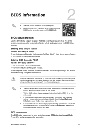
... clear the CMOS and reset the motherboard to guide you do not press or , POST continues with its parameters. Select the Load Optimized Defaults item under two modes: EZ Mode and Advanced Mode. Entering BIOS Setup at startup To enter BIOS Setup at www.asus.com to download the latest BIOS file for information on the system chassis. Press the power button to change between the two modes. ASUS PRIME B450M-A 2-1 BIOS information • Scan the QR code to view the BIOS update guide...
... clear the CMOS and reset the motherboard to guide you do not press or , POST continues with its parameters. Select the Load Optimized Defaults item under two modes: EZ Mode and Advanced Mode. Entering BIOS Setup at startup To enter BIOS Setup at www.asus.com to download the latest BIOS file for information on the system chassis. Press the power button to change between the two modes. ASUS PRIME B450M-A 2-1 BIOS information • Scan the QR code to view the BIOS update guide...


