
User Guide
Page 1
P9D-X Motherboard
P9D-X Motherboard
User Guide
Page 3
... guide...x How this guide is organized x Where to find more information x P9D-X Specifications Summary xii Chapter 1: Product Introduction 1.1 Welcome!...1-3 1.2 Package contents 1-3 1.3 Serial number label 1-4 1.4 Special features 1-4 1.4.1 Product highlights 1-4 1.4.2 Innovative ASUS features 1-6 Chapter 2: Hardware Information 2.1 Before you proceed 2-3 2.2 Motherboard overview 2-4 2.2.1 Placement direction 2-4 2.2.2 Screw holes 2-4 2.2.3 Motherboard layout 2-5 2.2.4 Layout contents 2-6 2.3 Central Processing Unit (CPU 2-8 2.3.1 Installing the CPU...
... guide...x How this guide is organized x Where to find more information x P9D-X Specifications Summary xii Chapter 1: Product Introduction 1.1 Welcome!...1-3 1.2 Package contents 1-3 1.3 Serial number label 1-4 1.4 Special features 1-4 1.4.1 Product highlights 1-4 1.4.2 Innovative ASUS features 1-6 Chapter 2: Hardware Information 2.1 Before you proceed 2-3 2.2 Motherboard overview 2-4 2.2.1 Placement direction 2-4 2.2.2 Screw holes 2-4 2.2.3 Motherboard layout 2-5 2.2.4 Layout contents 2-6 2.3 Central Processing Unit (CPU 2-8 2.3.1 Installing the CPU...
User Guide
Page 8
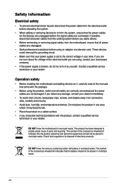
... equipment) should not be placed in municipal waste. Contact a qualified service technician or your area. Operation safety • Before installing the motherboard and adding devices on a stable surface. • If you detect any damage, contact your power supply is broken, do not try to...not sure about the voltage of the electrical outlet you add a device. • Before connecting or removing signal cables from the motherboard, ensure that all power cables from the existing system before you are connected. Safety information Electrical safety • To prevent electrical ...
... equipment) should not be placed in municipal waste. Contact a qualified service technician or your area. Operation safety • Before installing the motherboard and adding devices on a stable surface. • If you detect any damage, contact your power supply is broken, do not try to...not sure about the voltage of the electrical outlet you add a device. • Before connecting or removing signal cables from the motherboard, ensure that all power cables from the existing system before you are connected. Safety information Electrical safety • To prevent electrical ...
User Guide
Page 10
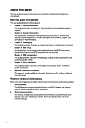
...been added by your dealer. How this guide This user guide contains the information you may have to when configuring the motherboard. Where to find more information Refer to the following parts: • Chapter 1: Product introduction This chapter describes the features... is organized This user guide contains the following sources for additional information and for product and software updates. 1. ASUS websites The ASUS website provides updated information on the motherboard. • Chapter 3: Powering up This chapter describes the power up , creating, and configuring RAID sets using...
...been added by your dealer. How this guide This user guide contains the information you may have to when configuring the motherboard. Where to find more information Refer to the following parts: • Chapter 1: Product introduction This chapter describes the features... is organized This user guide contains the following sources for additional information and for product and software updates. 1. ASUS websites The ASUS website provides updated information on the motherboard. • Chapter 3: Powering up This chapter describes the power up , creating, and configuring RAID sets using...

User Guide
Page 16
This chapter contains the following sections: 1.1 Welcome!...1-3 1.2 Package contents 1-3 1.3 Serial number label 1-4 1.4 Special features 1-4 ASUS P9D-X Chapter summary 1 This chapter describes the motherboard features and the new technologies it supports.
This chapter contains the following sections: 1.1 Welcome!...1-3 1.2 Package contents 1-3 1.3 Serial number label 1-4 1.4 Special features 1-4 ASUS P9D-X Chapter summary 1 This chapter describes the motherboard features and the new technologies it supports.
User Guide
Page 17
ASUS P9D-X 1-3 Before you for LGA1150 Packaging Qty. 1 1 4 2 1 1 1 1 1 pc per carton Standard Bulk Pack 1 ---1 1 1 1 10 pcs per carton If any of ASUS quality motherboards! The motherboard delivers a host of new features and latest technologies, making it , check the items in the long line of the above items is damaged or missing, ...
ASUS P9D-X 1-3 Before you for LGA1150 Packaging Qty. 1 1 4 2 1 1 1 1 1 pc per carton Standard Bulk Pack 1 ---1 1 1 1 10 pcs per carton If any of ASUS quality motherboards! The motherboard delivers a host of new features and latest technologies, making it , check the items in the long line of the above items is damaged or missing, ...
User Guide
Page 18
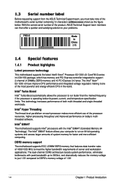
1.3 Serial number label Before requesting support from the ASUS Technical Support team, you must take note of the processor resources, higher processing throughout and improved performance on today's multithreaded software. Intel® Hyper... the marked frequency if the processor is operating below . The Intel® EM64T feature allows your problems. P9D-X xxS2xxxxxxxx Made in China 合格 1.4 Special features 1.4.1 Product highlights Latest processor technology This motherboard supports the latest Intel® Xeon® Processor E3-1200 v3/ CoreTM i3 series in the world. ...
1.3 Serial number label Before requesting support from the ASUS Technical Support team, you must take note of the processor resources, higher processing throughout and improved performance on today's multithreaded software. Intel® Hyper... the marked frequency if the processor is operating below . The Intel® EM64T feature allows your problems. P9D-X xxS2xxxxxxxx Made in China 合格 1.4 Special features 1.4.1 Product highlights Latest processor technology This motherboard supports the latest Intel® Xeon® Processor E3-1200 v3/ CoreTM i3 series in the world. ...
User Guide
Page 19
... the CPU resources by automatically adjusting the CPU voltage and core frequency depending on USB 2.0. USB 2.0 technology The motherboard implements the Universal Serial Bus (USB) 2.0 specification that provides twice the performance and speed of current for critical components...), Power Management (PM) Implementation Algorithm, and Hot Swap. ASUS P9D-X 1-5 USB 3.0 technology The motherboard implements the USB 3.0 technology with lower pin count and reduced voltage requirements. Serial ATA II technology The motherboard supports the Serial ATA II 3 Gb/s technology through the...
... the CPU resources by automatically adjusting the CPU voltage and core frequency depending on USB 2.0. USB 2.0 technology The motherboard implements the Universal Serial Bus (USB) 2.0 specification that provides twice the performance and speed of current for critical components...), Power Management (PM) Implementation Algorithm, and Hot Swap. ASUS P9D-X 1-5 USB 3.0 technology The motherboard implements the USB 3.0 technology with lower pin count and reduced voltage requirements. Serial ATA II technology The motherboard supports the Serial ATA II 3 Gb/s technology through the...

User Guide
Page 22
This chapter contains the following sections: 2.1 Before you have to perform when installing system components. It includes description of the jumpers and connectors on the motherboard. Chapter summary 2 This chapter lists the hardware setup procedures that you proceed 2-3 2.2 Motherboard overview 2-4 2.3 Central Processing Unit (CPU 2-8 2.4 System memory 2-14 2.5 Expansion slots 2-16 2.6 Onboard LEDs 2-21 2.7 Jumpers...2-24 2.8 Connectors 2-29 Chapter 1: Product introduction
This chapter contains the following sections: 2.1 Before you have to perform when installing system components. It includes description of the jumpers and connectors on the motherboard. Chapter summary 2 This chapter lists the hardware setup procedures that you proceed 2-3 2.2 Motherboard overview 2-4 2.3 Central Processing Unit (CPU 2-8 2.4 System memory 2-14 2.5 Expansion slots 2-16 2.6 Onboard LEDs 2-21 2.7 Jumpers...2-24 2.8 Connectors 2-29 Chapter 1: Product introduction
User Guide
Page 23
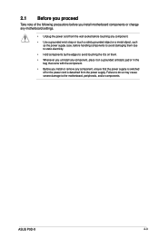
...ASUS P9D-X 2-3 Failure to do so may cause severe damage to avoid touching the ICs on them. • Whenever you uninstall any component, place it on a grounded antistatic pad or in the bag that came with the component. • Before you install motherboard components or change any motherboard... settings. • Unplug the power cord from the wall socket before handling components to avoid damaging them due to static electricity. • Hold components by the edges to the motherboard, peripherals, and/or components...
...ASUS P9D-X 2-3 Failure to do so may cause severe damage to avoid touching the ICs on them. • Whenever you uninstall any component, place it on a grounded antistatic pad or in the bag that came with the component. • Before you install motherboard components or change any motherboard... settings. • Unplug the power cord from the wall socket before handling components to avoid damaging them due to static electricity. • Hold components by the edges to the motherboard, peripherals, and/or components...

User Guide
Page 24
...Ensure to the chassis. Place this side towards the rear of the chassis 2-4 Chapter 2: Hardware information To optimize the motherboard features, we highly recommend that you place it into the chassis in the correct orientation. DO NOT overtighten the screws!...indicated by circles to secure the motherboard to unplug the chassis power cord before installing or removing the motherboard. 2.2 Motherboard overview Before you install the motherboard, study the configuration of your chassis to do so can damage the motherboard. Failure to ensure that the motherboard fits into it. Doing so ...
...Ensure to the chassis. Place this side towards the rear of the chassis 2-4 Chapter 2: Hardware information To optimize the motherboard features, we highly recommend that you place it into the chassis in the correct orientation. DO NOT overtighten the screws!...indicated by circles to secure the motherboard to unplug the chassis power cord before installing or removing the motherboard. 2.2 Motherboard overview Before you install the motherboard, study the configuration of your chassis to do so can damage the motherboard. Failure to ensure that the motherboard fits into it. Doing so ...
User Guide
Page 25
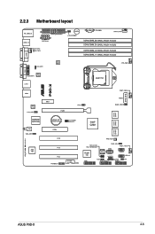
2.2.3 Motherboard layout ASUS P9D-X 2-5
2.2.3 Motherboard layout ASUS P9D-X 2-5
User Guide
Page 28
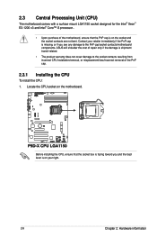
ASUS will shoulder the cost of repair only if the damage is shipment/ transit-related. • The product warranty does not cover damage to the PnP cap/socket contacts/motherboard components. Before installing the CPU, ensure that the PnP cap is on the motherboard. Contact your retailer immediately if ... for the Intel® Xeon® E3-1200 v3 and Intel® Core™ i3 processor.. • Upon purchase of the motherboard, ensure that the socket box is facing toward you see any damage to the socket contacts resulting from incorrect CPU installation/removal, or misplacement...
ASUS will shoulder the cost of repair only if the damage is shipment/ transit-related. • The product warranty does not cover damage to the PnP cap/socket contacts/motherboard components. Before installing the CPU, ensure that the PnP cap is on the motherboard. Contact your retailer immediately if ... for the Intel® Xeon® E3-1200 v3 and Intel® Core™ i3 processor.. • Upon purchase of the motherboard, ensure that the socket box is facing toward you see any damage to the socket contacts resulting from incorrect CPU installation/removal, or misplacement...
User Guide
Page 31
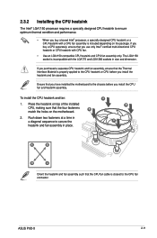
... buy a CPU separately, ensure that you have installed the motherboard to the chassis before you buy a boxed Intel® processor, a specially designed CPU heatsink or a CPU heatsink with the LGA775 and LGA1366 sockets in place. ASUS P9D-X 2-11 The LGA1150 socket is incompatible with a CPU fan... in size and dimension. Place the heatsink on top of the installed CPU, making sure that the CPU fan cable is included depending on the motherboard. 2. A B A A B B A Orient the heatsink and fan assembly such that the four fasteners B match the holes on the package. 2.3.2 ...
... buy a CPU separately, ensure that you have installed the motherboard to the chassis before you buy a boxed Intel® processor, a specially designed CPU heatsink or a CPU heatsink with the LGA775 and LGA1366 sockets in place. ASUS P9D-X 2-11 The LGA1150 socket is incompatible with a CPU fan... in size and dimension. Place the heatsink on top of the installed CPU, making sure that the CPU fan cable is included depending on the motherboard. 2. A B A A B B A Orient the heatsink and fan assembly such that the four fasteners B match the holes on the package. 2.3.2 ...

User Guide
Page 32
... sequence to plug this connector. 2.3.3 Uninstalling the CPU heatsink and fan To uninstall the CPU heatsink and fan: 1. Disconnect the CPU fan cable from the motherboard. 2-12 Chapter 2: Hardware information Rotate each fastener counterclockwise. B 3. 3. Connect the CPU fan cable to connect the CPU fan connector! DO NOT forget to the connector...
... sequence to plug this connector. 2.3.3 Uninstalling the CPU heatsink and fan To uninstall the CPU heatsink and fan: 1. Disconnect the CPU fan cable from the motherboard. 2-12 Chapter 2: Hardware information Rotate each fastener counterclockwise. B 3. 3. Connect the CPU fan cable to connect the CPU fan connector! DO NOT forget to the connector...
User Guide
Page 33
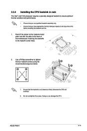
... the thermal interface material to tighten the four heatsink screws using the recommended sequence below. Doing so can damage the CPU. ASUS P9D-X 2-13 Use a Phillips screwdriver to the top of the motherboard, matching the standoffs to the heatsink screw holes. 2. Do not overtighten the screws. A C D B A C D B 1. 2.3.4 Installing the CPU heatsink in rack The...
... the thermal interface material to tighten the four heatsink screws using the recommended sequence below. Doing so can damage the CPU. ASUS P9D-X 2-13 Use a Phillips screwdriver to the top of the motherboard, matching the standoffs to the heatsink screw holes. 2. Do not overtighten the screws. A C D B A C D B 1. 2.3.4 Installing the CPU heatsink in rack The...
User Guide
Page 34
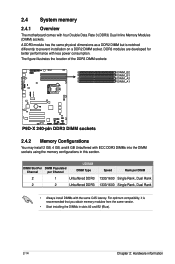
... Configurations You may install 2 GB, 4 GB, and 8 GB Unbuffered with four Double Data Rate 3 (DDR3) Dual Inline Memory Modules (DIMM) sockets. 2.4 System memory 2.4.1 Overview The motherboard comes with ECC DDR3 DIMMs into the DIMM sockets using the memory configurations in slots A2 and B2 (Blue). 2-14 Chapter 2: Hardware information
... Configurations You may install 2 GB, 4 GB, and 8 GB Unbuffered with four Double Data Rate 3 (DDR3) Dual Inline Memory Modules (DIMM) sockets. 2.4 System memory 2.4.1 Overview The motherboard comes with ECC DDR3 DIMMs into the DIMM sockets using the memory configurations in slots A2 and B2 (Blue). 2-14 Chapter 2: Hardware information
User Guide
Page 35
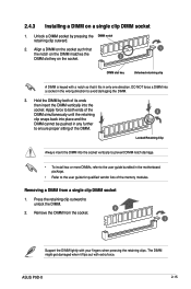
Locked Retaining Clip Always insert the DIMM into a socket in the motherboard package. • Refer to avoid damaging the DIMM. 3. The DIMM might get damaged when it fits in any further to unlock the DIMM. 2 2. DO NOT ... snaps back into the socket. Remove the DIMM from a single clip DIMM socket 1. Removing a DIMM from the socket. 1 Support the DIMM lightly with extra force. ASUS P9D-X 2-15 Hold the DIMM by pressing the DIMM notch retaining clip outward. 2. 2.4.3 Installing a DIMM on the socket. 2 DIMM slot key Unlocked retaining clip A DIMM is...
Locked Retaining Clip Always insert the DIMM into a socket in the motherboard package. • Refer to avoid damaging the DIMM. 3. The DIMM might get damaged when it fits in any further to unlock the DIMM. 2 2. DO NOT ... snaps back into the socket. Remove the DIMM from a single clip DIMM socket 1. Removing a DIMM from the socket. 1 Support the DIMM lightly with extra force. ASUS P9D-X 2-15 Hold the DIMM by pressing the DIMM notch retaining clip outward. 2. 2.4.3 Installing a DIMM on the socket. 2 DIMM slot key Unlocked retaining clip A DIMM is...
User Guide
Page 36
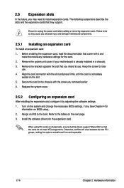
Ensure to the card. Remove the bracket opposite the slot that came with the screw you physical injury and damage motherboard components. 2.5.1 Installing an expansion card To install an expansion card: 1. Align the card connector with the slot and press firmly until the card is... system and change the necessary BIOS settings, if any. Failure to do not need to install expansion cards. Remove the system unit cover (if your motherboard is completely seated on BIOS setup. 2. Secure the card to the chassis with it by adjusting the software settings. 1. Turn on the next page. 3. 2.5...
Ensure to the card. Remove the bracket opposite the slot that came with the screw you physical injury and damage motherboard components. 2.5.1 Installing an expansion card To install an expansion card: 1. Align the card connector with the slot and press firmly until the card is... system and change the necessary BIOS settings, if any. Failure to do not need to install expansion cards. Remove the system unit cover (if your motherboard is completely seated on BIOS setup. 2. Secure the card to the chassis with it by adjusting the software settings. 1. Turn on the next page. 3. 2.5...
User Guide
Page 39
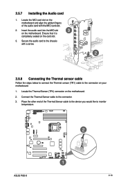
... align the golden fingers of the Thermal Sensor cable to the device you would like to the connector on your motherboard. 1. Place the other end of the audio card with a screw. 2.5.8 Connecting the Thermal sensor cable Follow the steps below to connect the Thermal sensor (TR1) ... slot on the card slot. 3. Secure the audio card to the connector. 3. Connect the Thermal Sensor cable to the chassis with the MIO card slot. 2. ASUS P9D-X 2-19 2.5.7 Installing the Audio card 1.
... align the golden fingers of the Thermal Sensor cable to the device you would like to the connector on your motherboard. 1. Place the other end of the audio card with a screw. 2.5.8 Connecting the Thermal sensor cable Follow the steps below to connect the Thermal sensor (TR1) ... slot on the card slot. 3. Secure the audio card to the connector. 3. Connect the Thermal Sensor cable to the chassis with the MIO card slot. 2. ASUS P9D-X 2-19 2.5.7 Installing the Audio card 1.

